EP1970612A1 - Système de raccord d'angle pour brides d'assemblage de canaux en tôle - Google Patents
Système de raccord d'angle pour brides d'assemblage de canaux en tôle Download PDFInfo
- Publication number
- EP1970612A1 EP1970612A1 EP08004226A EP08004226A EP1970612A1 EP 1970612 A1 EP1970612 A1 EP 1970612A1 EP 08004226 A EP08004226 A EP 08004226A EP 08004226 A EP08004226 A EP 08004226A EP 1970612 A1 EP1970612 A1 EP 1970612A1
- Authority
- EP
- European Patent Office
- Prior art keywords
- leg
- apex
- portions
- corner angle
- angle system
- Prior art date
- Legal status (The legal status is an assumption and is not a legal conclusion. Google has not performed a legal analysis and makes no representation as to the accuracy of the status listed.)
- Withdrawn
Links
- 239000002184 metal Substances 0.000 title claims description 10
- 238000003780 insertion Methods 0.000 claims description 20
- 230000037431 insertion Effects 0.000 claims description 20
- 238000007373 indentation Methods 0.000 claims description 4
- 230000007704 transition Effects 0.000 claims description 4
- 239000013585 weight reducing agent Substances 0.000 claims description 4
- 239000011324 bead Substances 0.000 claims description 2
- 206010000496 acne Diseases 0.000 abstract 2
- 238000004049 embossing Methods 0.000 description 6
- 230000008901 benefit Effects 0.000 description 4
- 238000005520 cutting process Methods 0.000 description 4
- 238000004519 manufacturing process Methods 0.000 description 3
- 208000027418 Wounds and injury Diseases 0.000 description 2
- 230000006378 damage Effects 0.000 description 2
- 208000014674 injury Diseases 0.000 description 2
- 238000007493 shaping process Methods 0.000 description 2
- 238000005452 bending Methods 0.000 description 1
- 230000015572 biosynthetic process Effects 0.000 description 1
- 230000006872 improvement Effects 0.000 description 1
- 238000000034 method Methods 0.000 description 1
- 230000008092 positive effect Effects 0.000 description 1
- 230000008569 process Effects 0.000 description 1
- 230000009467 reduction Effects 0.000 description 1
- 230000003716 rejuvenation Effects 0.000 description 1
Images

Classifications
-
- F—MECHANICAL ENGINEERING; LIGHTING; HEATING; WEAPONS; BLASTING
- F24—HEATING; RANGES; VENTILATING
- F24F—AIR-CONDITIONING; AIR-HUMIDIFICATION; VENTILATION; USE OF AIR CURRENTS FOR SCREENING
- F24F13/00—Details common to, or for air-conditioning, air-humidification, ventilation or use of air currents for screening
- F24F13/02—Ducting arrangements
- F24F13/0209—Ducting arrangements characterised by their connecting means, e.g. flanges
-
- F—MECHANICAL ENGINEERING; LIGHTING; HEATING; WEAPONS; BLASTING
- F16—ENGINEERING ELEMENTS AND UNITS; GENERAL MEASURES FOR PRODUCING AND MAINTAINING EFFECTIVE FUNCTIONING OF MACHINES OR INSTALLATIONS; THERMAL INSULATION IN GENERAL
- F16L—PIPES; JOINTS OR FITTINGS FOR PIPES; SUPPORTS FOR PIPES, CABLES OR PROTECTIVE TUBING; MEANS FOR THERMAL INSULATION IN GENERAL
- F16L23/00—Flanged joints
- F16L23/12—Flanged joints specially adapted for particular pipes
- F16L23/14—Flanged joints specially adapted for particular pipes for rectangular pipes
Definitions
- the invention relates to a Eckwinkelsystem for kausflanschabroughe of sheet metal channel sections, with a first and a second leg portion, each having a plug-in in a kausflanschabrough insertion portion and a vertex portion, wherein the two leg portions have the same wall thickness and their apex portions in the free corner region of adjacent Vietnamesesflanschabroughe overlap and each formed with a screw hole, and each of the two leg portions between the male portion and the apex portion has a fold and at the side facing away from the insertion portion outer end of the apex portion has a beaded edge.
- Such Eckwinkelsystem is from the DE 10 2005 042 016 B3 known to the applicant.
- the bead of a leg member is formed with a plug-in portion facing its locking nub and the second leg member at the associated longitudinal edge with a locking recess into which the locking nub in the Connecting flange sections inserted state of the two leg parts positively engages.
- a leg portion is formed with a locking recess and the other leg portion with a locking nub.
- the invention is therefore an object of the invention to provide a Eckwinkelsystem of the type mentioned, in which the tool cost for the production of the two leg parts substantially reduced and at the same time the definition of the two leg parts in the associated Vietnamesesflanschabitesen a Bleckkanalabiteses is further improved.
- both leg portions are each formed with a latching nub and a latching recess, there is the advantage of improved locking of the two leg portions and thus improving the strength of the connection of the two inserted into the kausflanschabitese leg portions.
- the reduction of the cost of the cutting tool is thus accompanied by an improvement in the lock and the strength of the connection of the two leg parts.
- the insertion portions of the two leg portions are each formed with an elongated indentation.
- These dents can be made simultaneously with the folds of the two leg parts with the aid of the embossing stamp mentioned above. With the help of said dents, an improved fixation of the leg parts in the connecting flange sections of a sheet-metal channel section is also realized.
- the end portion facing away from the apex portion of the insertion of the respective leg portion is formed with a tapering edge. From the point of view of minimizing a risk of injury, it is advantageous if the said tapering edge is formed with rounded edges.
- the Figures 1 and 2 show a first leg portion 10 of the Eckwinkelsystems for kausflanschabroughe of sheet metal duct sections.
- the first leg part 10 has an insertion section 12 and a vertex section 14.
- the insertion portion 12 and the apex portion 14 have the same width dimension.
- Between the insertion portion 12 and the apex portion 14 a fold 16 is formed.
- W is in FIG. 2 the wall thickness of the first Leg portion 10, ie its Einsteckabêtes 12 and its leg portion 14, respectively.
- the first leg part 10 has an outer longitudinal edge 18 and an inner longitudinal edge 20.
- the apex section 14 At the outer end 22 of the apex section 14 facing away from the insertion section 12, the apex section 14 has a beading edge 24, which projects away from the apex section 14 in the direction of the bent-over insertion section 12.
- the beading 24 is formed with a locking nub 26.
- the latching nub 26 is provided on the inner longitudinal edge 20 facing the inner end 28 of the flanged edge 24.
- the first leg portion 10 is also formed with a locking recess 30 which is provided on the outer longitudinal edge 18 at the apex portion 14 in the vicinity of the fold 16.
- FIGS. 3 and 4 show the second leg portion 32 which is formed with the same edge contours as the first leg portion 10, wherein in the FIGS. 3 and 4 same details with the same reference numerals as in the Figures 1 and 2 are designated.
- the only difference between the first and the second leg portion 10 and 32 is that the fold 16 between the plug portion 12 and the apex portion 14 is oriented in the other direction.
- the two leg parts 10 and 32 can be produced with a single cutting tool.
- the embossing, ie shaping of the second leg portion 32 is possible with the same die as the embossing of the first leg portion 10, it only needs the die for shaping the second leg portion 32 to be rotated by 180 °.
- the respective flanged edge 24 has between its distal locking nub 26 and its proximal inner end 34 has a width b which is smaller than the width B of the respective leg portion 10, 32.
- b B / 2.
- the apex portion 14 of the respective leg portion 10, 32 is formed with a screw hole 36.
- the respective screw hole 36 is preferably provided in the center of the associated apex portion 14.
- the respective apex portion 14 of the first and second leg portion 10, 32 is formed in the transition region 38 between its outer longitudinal edge 18 and its outer end 22 with a rounded portion 40.
- the insertion portion 12 of the respective leg portion 10, 32 is formed with an elongated indentation 42.
- the end portion 44 of the insertion portion 12 of the respective leg portion 10, 32 facing away from the apex portion 14 is formed with a tapered edge 46.
- the tapering rim 46 is formed with rounded portions 48.
- the end portion 44 of the insertion portion 12 of the respective leg portion 10, 32 is formed with a weight reduction hole 50.
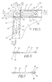
- FIGS. 5, 6 and 7 illustrate the Eckwinkelsystem 52, consisting of the first and the second leg portion 10 and 32 in the assembled and firmly connected state, wherein the Kirsflanschabête 54 of a sheet metal channel section 56 in FIG. 5 are shown in sections with thin lines.
- FIGS. 5 to 7 are the same details with the same reference numerals as in the FIGS. 1 to 4 designated, so that it is unnecessary, in conjunction with the FIGS. 5 to 7 to describe all the details again in detail.
Landscapes
- Engineering & Computer Science (AREA)
- General Engineering & Computer Science (AREA)
- Mechanical Engineering (AREA)
- Chemical & Material Sciences (AREA)
- Combustion & Propulsion (AREA)
- Duct Arrangements (AREA)
- Connection Of Plates (AREA)
Applications Claiming Priority (1)
| Application Number | Priority Date | Filing Date | Title |
|---|---|---|---|
| DE200710012015 DE102007012015B3 (de) | 2007-03-13 | 2007-03-13 | Eckwinkelsystem für Verbindungsflanschabschnitte von Blechkanalabschnitten |
Publications (1)
| Publication Number | Publication Date |
|---|---|
| EP1970612A1 true EP1970612A1 (fr) | 2008-09-17 |
Family
ID=39510121
Family Applications (1)
| Application Number | Title | Priority Date | Filing Date |
|---|---|---|---|
| EP08004226A Withdrawn EP1970612A1 (fr) | 2007-03-13 | 2008-03-07 | Système de raccord d'angle pour brides d'assemblage de canaux en tôle |
Country Status (2)
| Country | Link |
|---|---|
| EP (1) | EP1970612A1 (fr) |
| DE (1) | DE102007012015B3 (fr) |
Cited By (1)
| Publication number | Priority date | Publication date | Assignee | Title |
|---|---|---|---|---|
| WO2010088334A1 (fr) * | 2009-01-29 | 2010-08-05 | Duro Dyne Corporation | Raccord d'angles coulissants pour bride |
Families Citing this family (1)
| Publication number | Priority date | Publication date | Assignee | Title |
|---|---|---|---|---|
| EA201171104A1 (ru) * | 2009-03-05 | 2012-04-30 | Хермануссен Металлферарбайтунг Гмбх | Фланцевый профиль для герметичного соединения воздушного канала |
Citations (5)
| Publication number | Priority date | Publication date | Assignee | Title |
|---|---|---|---|---|
| EP0151075A2 (fr) * | 1984-01-31 | 1985-08-07 | Rafael Garcia | Raccords à brides pour tuyauteries |
| WO1990005263A1 (fr) * | 1988-11-12 | 1990-05-17 | Firmac Limited | Elements de jonction pour canalisation |
| EP1491827A1 (fr) * | 2002-04-01 | 2004-12-29 | Fuji Kuuchou Kougyou Co., Ltd | Ensemble conduite pour conditionneur d'air |
| AT413878B (de) * | 2004-08-19 | 2006-06-15 | Aumayr Gmbh & Co Leopold | Eckverbindung für die abgekanteten wandflansche eines im querschnitt rechtwinkeligen blechkanalschusses |
| DE102005042016B3 (de) | 2005-09-02 | 2007-01-11 | Ing.-Büro H. Prechtl KG Anlagentechnik | Eckwinkelsystem für Verbindungsflansche von Blechkanalabschnitten |
Family Cites Families (3)
| Publication number | Priority date | Publication date | Assignee | Title |
|---|---|---|---|---|
| DE7408661U (fr) * | 1974-09-19 | Meinig K Kg | ||
| DE3340503C1 (de) * | 1983-11-09 | 1985-02-07 | Karl Meinig KG, 7201 Rietheim-Weilheim | Zweiteiliges Eckwinkelstueck fuer Verbindungsflansche von Blechkanalabschnitten |
| FR2795802B1 (fr) * | 1999-07-01 | 2001-08-17 | Ct Est Ventilation | Dispositif de liaison a bride a haute rigidite |
-
2007
- 2007-03-13 DE DE200710012015 patent/DE102007012015B3/de not_active Expired - Fee Related
-
2008
- 2008-03-07 EP EP08004226A patent/EP1970612A1/fr not_active Withdrawn
Patent Citations (5)
| Publication number | Priority date | Publication date | Assignee | Title |
|---|---|---|---|---|
| EP0151075A2 (fr) * | 1984-01-31 | 1985-08-07 | Rafael Garcia | Raccords à brides pour tuyauteries |
| WO1990005263A1 (fr) * | 1988-11-12 | 1990-05-17 | Firmac Limited | Elements de jonction pour canalisation |
| EP1491827A1 (fr) * | 2002-04-01 | 2004-12-29 | Fuji Kuuchou Kougyou Co., Ltd | Ensemble conduite pour conditionneur d'air |
| AT413878B (de) * | 2004-08-19 | 2006-06-15 | Aumayr Gmbh & Co Leopold | Eckverbindung für die abgekanteten wandflansche eines im querschnitt rechtwinkeligen blechkanalschusses |
| DE102005042016B3 (de) | 2005-09-02 | 2007-01-11 | Ing.-Büro H. Prechtl KG Anlagentechnik | Eckwinkelsystem für Verbindungsflansche von Blechkanalabschnitten |
Cited By (1)
| Publication number | Priority date | Publication date | Assignee | Title |
|---|---|---|---|---|
| WO2010088334A1 (fr) * | 2009-01-29 | 2010-08-05 | Duro Dyne Corporation | Raccord d'angles coulissants pour bride |
Also Published As
| Publication number | Publication date |
|---|---|
| DE102007012015B3 (de) | 2008-07-17 |
Similar Documents
| Publication | Publication Date | Title |
|---|---|---|
| DE112010002979T5 (de) | Kompressionsbegrenzer mit Arretierungsmerkmalen | |
| EP3612698A1 (fr) | Charnière pour boîtier d'armoire de commande ainsi que boîtier d'armoire de commande et procédé de montage correspondants | |
| EP0141306A1 (fr) | Raccord de cornière d'angle en deux morceaux pour brides d'assemblage de canaux en tôle | |
| EP2429734A1 (fr) | Tiroir muni de deux parois latérales et d'une paroi arrière | |
| EP3110587A1 (fr) | Système de fixation destiné à une panne | |
| WO2016100992A1 (fr) | Procédé de liaison d'éléments d'armature de meuble et armature de meuble | |
| DE102007012015B3 (de) | Eckwinkelsystem für Verbindungsflanschabschnitte von Blechkanalabschnitten | |
| EP1733164A1 (fr) | Raccord enfichable a blocage angulaire | |
| DE3047820C2 (de) | Verfahren zur Herstellung eines Sicherungselementes zum axialen Festlegen von Bolzen, Wellen oder dergleichen | |
| EP0373527A2 (fr) | Elément pour murs et/ou plafonds | |
| DE102013011966A1 (de) | Verfahren zur Herstellung einer Doppelschiene sowie Doppelschiene | |
| DE102014017786B4 (de) | Befestigungsblech mit einem Fixierhaken sowie Gurtaufroller und Fahrzeugkarosserie mit einem Befestigungsblech | |
| DE202017001165U1 (de) | Snapverbinder | |
| EP1760383B1 (fr) | Système de raccord d'angle pour brides d'assemblage de canaux en tôle | |
| DE3533951A1 (de) | Rohrschelle, insbesondere zum verankern von regenfallrohren | |
| EP3315018A1 (fr) | Cornière, utilisation de ladite cornière comme bordure, ensemble de bordure et procédé de pose de bordures | |
| AT522842B1 (de) | Schubladenrückwand | |
| EP2570765B1 (fr) | Mètre pliant | |
| DE102005059129A1 (de) | Gehäuse eines Verstellantriebes, insbesondere eines Schrittschaltwerkes eines Kraftfahrzeugsitzes | |
| EP3315019A1 (fr) | Element de coin, utilisation dudit element, procede de production dudit element de coin et ensemble de bordures contenant ledit element | |
| DE29917894U1 (de) | Abdeckkasten für teleskopartige Abdeckungen | |
| DE102023003062A1 (de) | Grundkörper für ein Stanzteil, insbesondere für eine Hülse, ein aus diesem Grundkörper hergestelltes Stanzteil, insbesondere eine Hülse, sowie ein Verfahren zur Herstellung einer Verbindung zweier Materialbereiche, insbesondere zur Herstellung eines Stanzteils aus einem Grundkörper | |
| DE202023001563U1 (de) | Grundkörper für ein Stanzteil, insbesondere für eine Hülse, und ein aus diesem Grundkörper hergestelltes Stanzteil, insbesondere eine Hülse | |
| EP1580490A2 (fr) | Panneau frontal pour radiateur et procédé de fabrication du panneau | |
| DE20209784U1 (de) | Rohrschelle |
Legal Events
| Date | Code | Title | Description |
|---|---|---|---|
| PUAI | Public reference made under article 153(3) epc to a published international application that has entered the european phase |
Free format text: ORIGINAL CODE: 0009012 |
|
| AK | Designated contracting states |
Kind code of ref document: A1 Designated state(s): AT BE BG CH CY CZ DE DK EE ES FI FR GB GR HR HU IE IS IT LI LT LU LV MC MT NL NO PL PT RO SE SI SK TR |
|
| AX | Request for extension of the european patent |
Extension state: AL BA MK RS |
|
| RAP1 | Party data changed (applicant data changed or rights of an application transferred) |
Owner name: HANS PRECHTL GMBH & CO. KG |
|
| AKX | Designation fees paid | ||
| STAA | Information on the status of an ep patent application or granted ep patent |
Free format text: STATUS: THE APPLICATION IS DEEMED TO BE WITHDRAWN |
|
| 18D | Application deemed to be withdrawn |
Effective date: 20090318 |
|
| REG | Reference to a national code |
Ref country code: DE Ref legal event code: 8566 |