EP1970660A2 - Agencement et procédé destinés à la récupération d'énergie thermique à partir d'eaux usées - Google Patents
Agencement et procédé destinés à la récupération d'énergie thermique à partir d'eaux usées Download PDFInfo
- Publication number
- EP1970660A2 EP1970660A2 EP08151461A EP08151461A EP1970660A2 EP 1970660 A2 EP1970660 A2 EP 1970660A2 EP 08151461 A EP08151461 A EP 08151461A EP 08151461 A EP08151461 A EP 08151461A EP 1970660 A2 EP1970660 A2 EP 1970660A2
- Authority
- EP
- European Patent Office
- Prior art keywords
- inlet
- sewer
- arrangement according
- heat exchanger
- waste water
- Prior art date
- Legal status (The legal status is an assumption and is not a legal conclusion. Google has not performed a legal analysis and makes no representation as to the accuracy of the status listed.)
- Granted
Links
Images



Classifications
-
- F—MECHANICAL ENGINEERING; LIGHTING; HEATING; WEAPONS; BLASTING
- F28—HEAT EXCHANGE IN GENERAL
- F28D—HEAT-EXCHANGE APPARATUS, NOT PROVIDED FOR IN ANOTHER SUBCLASS, IN WHICH THE HEAT-EXCHANGE MEDIA DO NOT COME INTO DIRECT CONTACT
- F28D21/00—Heat-exchange apparatus not covered by any of the groups F28D1/00 - F28D20/00
-
- E—FIXED CONSTRUCTIONS
- E03—WATER SUPPLY; SEWERAGE
- E03F—SEWERS; CESSPOOLS
- E03F3/00—Sewer pipe-line systems
- E03F3/04—Pipes or fittings specially adapted to sewers
-
- E—FIXED CONSTRUCTIONS
- E03—WATER SUPPLY; SEWERAGE
- E03F—SEWERS; CESSPOOLS
- E03F5/00—Sewerage structures
- E03F5/18—Tanks for disinfecting, neutralising, or cooling sewage
-
- E—FIXED CONSTRUCTIONS
- E03—WATER SUPPLY; SEWERAGE
- E03C—DOMESTIC PLUMBING INSTALLATIONS FOR FRESH WATER OR WASTE WATER; SINKS
- E03C1/00—Domestic plumbing installations for fresh water or waste water; Sinks
- E03C2001/005—Installations allowing recovery of heat from waste water for warming up fresh water
-
- F—MECHANICAL ENGINEERING; LIGHTING; HEATING; WEAPONS; BLASTING
- F28—HEAT EXCHANGE IN GENERAL
- F28D—HEAT-EXCHANGE APPARATUS, NOT PROVIDED FOR IN ANOTHER SUBCLASS, IN WHICH THE HEAT-EXCHANGE MEDIA DO NOT COME INTO DIRECT CONTACT
- F28D21/00—Heat-exchange apparatus not covered by any of the groups F28D1/00 - F28D20/00
- F28D21/0001—Recuperative heat exchangers
- F28D21/0012—Recuperative heat exchangers the heat being recuperated from waste water or from condensates
-
- Y—GENERAL TAGGING OF NEW TECHNOLOGICAL DEVELOPMENTS; GENERAL TAGGING OF CROSS-SECTIONAL TECHNOLOGIES SPANNING OVER SEVERAL SECTIONS OF THE IPC; TECHNICAL SUBJECTS COVERED BY FORMER USPC CROSS-REFERENCE ART COLLECTIONS [XRACs] AND DIGESTS
- Y02—TECHNOLOGIES OR APPLICATIONS FOR MITIGATION OR ADAPTATION AGAINST CLIMATE CHANGE
- Y02B—CLIMATE CHANGE MITIGATION TECHNOLOGIES RELATED TO BUILDINGS, e.g. HOUSING, HOUSE APPLIANCES OR RELATED END-USER APPLICATIONS
- Y02B30/00—Energy efficient heating, ventilation or air conditioning [HVAC]
- Y02B30/56—Heat recovery units
Definitions
- the invention relates to an arrangement for the recovery of heat energy from waste water, which is associated with a sewer, with a buffer, which is connected via at least one inlet to the sewer and a heat exchanger, which is associated with the buffer, a sewer with a corresponding arrangement and a Process for the recovery of heat energy from waste water.
- the arrangement has, in addition to the heat exchanger and the buffer, a pump device, which is associated with the buffer and the promotion of waste water in the direction of the heat exchanger is used.
- the buffer is arranged such that the wastewater flowing through the sewer at least partially passes through the inlet into the buffer.
- the bottom of the buffer is expediently deeper than the bottom of the sewer, so that sewage enters the buffer even at low water level within the sewer.
- the buffer can be located inside the sewer, for example by the arrangement of corresponding walls, or in a niche in the wall of the sewer.
- the latter variant has the advantage that the cross section of the sewer is not reduced by internals. However, this makes it difficult to retrofit into an existing sewer compared to the first variant. With the help of the pumping device warm wastewater is finally fed from the buffer to the heat exchanger, which is connected in a conventional manner with another secondary circuit whose medium, usually water, to be heated.
- the heat exchanger After passing through the heat exchanger, the cooled wastewater flows back into the sewer via the drain.
- the heat exchanger can be located anywhere.
- the inlet has a filter device.
- the filter device has a mesh size that is adapted to the expected contamination is. If, for example, the wastewater carries muddy impurities, the mesh size must be chosen to be small enough to avoid the buffer being sanded. If, on the other hand, wastewater with impurities of a higher particle size is involved, then a corresponding sieve can also serve as a filter device.
- the filter device has a cleaning device, blockage of the filter device can be effectively counteracted. This is particularly advantageous when the wastewater contains slimy or sticky components which would lead to rapid clogging of the filter device.
- the cleaning device has a screw conveyor which moves the impurities retained by the filter device along the surface of the filter device in the direction of one end thereof.
- the mechanical cleaning which is caused by the sliding past the Schnekkeneriel on the surface of the filter device, additionally supported by a water flow, which is generated by the rotational movement of the screw.
- other cleaning devices for example in the form of scrapers, brushes or pneumatic devices are used.
- the inlet via the filter device is in communication with a drain, which in turn is connected to the sewer. If the impurities retained by the filter device are moved by the cleaning device in the direction of the drain, the wastewater flow, which flows from the heat exchanger back through the drain back into the sewer, causes the impurities also get back into the sewer. This will permanently and reliably prevents contamination over a longer period Period in the range of the filter device or the inlet or outlet can deposit.
- the heat exchanger has a return pipe whose end is located in the region of the drain.
- the inlet is arranged elevated with respect to the sewer bottom. This ensures that contaminants, which are mitgeschwemmt on the floor of the sewer, in particular sandy deposits, not even reach the area of the inlet or the filter device. This prevents a clogging of the filter device in a preventive manner and thus relieves the cleaning device.
- the pumping device is disposed within the buffer store, then this is located on the one hand at a location that is protected from contamination. In addition, if the pumping device is placed at the bottom of the buffer, it is easily possible to prevent the pumping device from drawing air. However, it is also conceivable to arrange the pump increased with respect to the intermediate storage bottom, so that possibly reaching into the temporary storage sandy deposits are not sucked by the pumping device.
- the cleaning device and / or the pumping device can be controlled via at least one control unit.
- the cleaning device at low pollution Waste water is operated only intermittently.
- the delivery rate of the pumping device is controllable according to the heat demand of the water circuit connected to the heat exchanger. For example, if the pumping device is completely shut down when no heat is needed or the temperature of the wastewater is insufficient for heat removal by means of the heat exchanger, overall energy consumption and wear is substantially minimized.
- control unit is assigned at least one temperature sensor, which serves to determine the temperature of the wastewater.
- the buffer and / or the secondary circuit accurate statements about the possible heat recovery can be obtained by the heat exchanger. If the wastewater has too low a temperature for a satisfactory heat exchange within the heat exchanger, then it is expedient to switch off the pump device or at least to throttle the delivery rate.
- At least one waste-water guide plate is assigned to the inlet and / or the outlet.
- the wastewater flows can be positively influenced.
- a baffle is arranged in the region of the inlet in such a way that it protrudes into the sewer against the sewage flow in the sewer, this ensures that a sufficient amount of warm wastewater always passes through the inlet into the intermediate store.
- one or more baffles can also or alternatively be arranged such that the waste water exiting the heat exchanger is directed via the filter device, where the contaminants accumulate, in order to rinse them back into the sewer.
- the baffles cause a mixing of the recirculated from the heat exchanger cooled wastewater with warm, through the inlet into the buffer inflowing waste water is mixed. As a result, the efficiency of the arrangement is significantly increased.
- the inlet and / or the outlet is associated with a shut-off device, for example in the form of a slide or a corresponding valve. If the obturator is closed, the arrangement, in particular the filter device, can be drained without further wastewater being able to flow into the arrangement. After completion of the repair and / or revision work the corresponding shut-off valves are opened again, so that the arrangement according to the invention can be put into operation again.
- a shut-off device for example in the form of a slide or a corresponding valve.
- the inlet is assigned a controllable closing device, then the amount of inflowing wastewater from the sewer into the intermediate store can be controlled in a simple manner.
- the controller may be connected, for example, with a temperature sensor. If the wastewater within the sewer has a temperature which is below the temperature which the wastewater has within the intermediate store, then it is expedient to close the closing device in order to avoid a cooling of the wastewater within the intermediate store.
- the pumping device and / or the cleaning device can also be activated in order to limit the operation of the device under unfavorable (temperature) conditions.
- closure devices hereby a variety of devices, such as poppet valves or various slides can be used. It is also conceivable, the Abwasserleitblech, which is located in the region of the inlet, pivotally form, so that this fulfills a dual function.
- the heat exchanger and / or the pumping device are outside the intermediate storage, a repair or replacement of the individual components is possible in a simple manner. Also, it may be appropriate be to accommodate the heat exchanger within a building, if it is in contact with several consumers. As a result, the number of necessary pipe connections can be kept as low as possible in a simple manner.
- this is designed in the form of a filter basket.
- the advantage of such a configuration is that the filter basket can be arranged vertically within the buffer. Thus, only a relatively small footprint is needed for the filter device within the buffer.
- the retained by the filter basket impurities are finally transported, for example, by means of a screw conveyor, which is associated with the filter basket in the direction of the drain and flushed by the back flowing from the heat exchanger wastewater back into the sewer.
- the inlet, the drain and / or the return pipe consist of several individual parts, which are connected to each other via a detachable connection.
- the said devices are integrated in most cases at least partially fixed in the sewer wall or one of the walls of the buffer. Due to the detachable connection, the filter device can now be separated from these parts and removed from the buffer. This is especially for revision and / or repair of enormous advantage.
- the filter device is associated with at least one guide device, this facilitates removal of the filter device from the intermediate store.
- the filter device can be pulled upwards, in particular after loosening said connections, for example with the aid of a crane through an opening of the buffer, while the guiding device prevents tilting of the filter device.
- An inventive sewer has an arrangement for the recovery of heat energy from wastewater according to the foregoing description.
- the arrangement can be subsequently integrated into existing sewers or even already be taken into account in the planning of new buildings.
- the method according to the invention for the recovery of heat energy from waste water is characterized in that wastewater is passed from a sewer via at least one inlet in a buffer, the wastewater is pumped from this buffer by means of a pumping device through at least one heat exchanger, and that of Returned cooling wastewater flowing back through a drain back into the sewer.
- the interposition of a buffer ensures that the wastewater is not fed to the heat exchanger directly from the sewer. Sewers of a sewer are always polluted by faeces, sand or other contaminants, unlike most household wastewaters, such as laundry or showers.
- By interposing a flow-stabilized buffer such impurities may settle or accumulate on the surface of the wastewater. If the wastewater is removed by a pumping device at a favorable location within the intermediate storage, impurities of the heat exchanger and also the pumping device are reliably prevented as a result of direct removal from the wastewater channel.
- waste water flowing in from the sewer is filtered in the region of the inlet by means of a filter device.
- contamination of the heat exchanger and the pumping device can be effectively counteracted, which has a particularly positive effect on the operating times of the respective devices, but also on the heat transfer to the heat exchanger surfaces.
- the contaminants retained by the filter device are moved by a cleaning device in the direction of the flow, it is achieved in a simple manner that the filter device does not become contaminated.
- the delivery rate of the pumping device is controlled as a function of the wastewater temperature within the sewer and / or the intermediate store.
- the delivery rate of the pumping device is controlled as a function of the wastewater temperature within the sewer and / or the intermediate store.
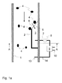
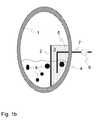
- FIG. 1 shows a particularly simple embodiment of the inventive arrangement for the recovery of heat energy from wastewater.
- an L-shaped partition wall 2 is used, which represents the vertical wall of the buffer 3.
- a filter device in the form of a screen plate 5 which simultaneously forms the inlet 6 of the buffer 3.
- the sewage flow is indicated by arrows.
- the wastewater flows through this screen plate 5 and accumulates within the buffer 3 to the height of the waste water level in the sewer 1 (see Fig. 1b ).
- a pipe 7, which is associated with a pumping device 8 opens.
- the pumping device 8 remote from the end of the pipe 7 is in turn connected to a heat exchanger 9, which in turn communicates with a secondary circuit 10, through which the water to be heated flows.
- the cooled wastewater is finally returned via a drain 13 in the sewer 1 again. It is expedient if the cooled wastewater is passed in the flow direction after the inlet 6 in the sewer 1, in order to avoid that cooled wastewater passes through the inlet 6 again in the buffer 3.
- the buffer 3 is also closed at the top, in order to avoid that at elevated water level within the sewer 1, for example due to heavy rainfall, impurities 4 get into the buffer 3.
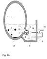
- FIG. 2 a further embodiment of the arrangement according to the invention is shown schematically.
- This also has a buffer 3, which is connected via an inlet 6 with a sewer 1.
- the buffer can be closed at the top as desired, for example, with the integration of a manhole.
- a vent opening In order to ensure a pressure equalization within the buffer 3, however, it is useful to assign the buffer 3, not shown, a vent opening.
- the inlet 6 is arranged elevated with respect to the sewer bed in order to avoid unnecessary loading of the filter device by sediments entrained at the bottom of the sewer 1, for example sand 25.
- the inlet 6 is assigned a waste water guide plate 11a (in FIG Fig. 2b not shown).
- the wastewater does not flow directly through the inlet 6 into the buffer 3, but must first pass through a substantially cylindrical filter device in the form of a screen plate 5.
- the filter device is assigned a cleaning device in the form of a transport screw 12. This moves by their rotation impurities 4 from the inlet 6 in the direction of the flow thirteenth
- the buffer 3 an external pump 8 and an external heat exchanger 9 is assigned. Both the heat exchanger 9 and the associated with this pumping device 8 can be arranged, for example, in an adjacent building, whereby a simple maintenance or replacement of the devices is ensured. As in FIG. 2 shown, but also an arrangement of the pumping device 8 within the buffer 3 is possible.
- the heat exchanger 9 a return pipe 14, the end of which opens into the region of the drain 13.
- the flow of the cooled waste water, which is generated by the pumping device 8 can be used to flush impurities 4 back into the sewer 1.
- the efficiency can be improved by the arrangement of Strömungsleitblechen not shown, which almost avoid mixing of the cooled wastewater with warm, reaching into the buffer 3 wastewater.
- Fig. 2a In addition, temperature sensors 16 are shown, which are connected to a control unit S. These can be arranged in the sewer 1, in the buffer 3 and / or within the secondary circuit 10 of the heat exchanger 9. As a result, a constant control of the corresponding temperatures or temperature differences is possible.
- the control unit S controls the delivery rate of the pumping device 8 in accordance with the detected data. For example, if the temperature in the buffer 3 is lower than in the secondary circuit 10, the wastewater no heat energy can be withdrawn, the pump 8 is turned off in this case.
- a movably mounted waste plate 11a that can be folded by a motor, not shown, in the direction of the inlet 6 and closes it, if the wastewater within the sewer 1 has a lower temperature than the wastewater within the temporary storage 3. As a result, the filter device is relieved. In parallel, it is of course also possible and useful to turn off the cleaning device as well. Also, the delivery rate of the pumping device 8 should be shut down in such a case, in order to avoid a draft of the pump 8.
- pumping device 8 and / or cleaning device can also be connected to level sensors, not shown. This can ensure that the arrangement is not operated when the sewer 1 no or very little wastewater leads.
- the inlet 6 and the outlet 13 are also shut-off valves, for example in the form of gate valves 17 assigned. As a result, inlet 6 and outlet 13 can be closed if repairs and / or revision work have to be made to the arrangement in order to prevent ingress of wastewater.
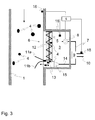
- FIG. 3 shows a schematic plan view of the arrangement according to the invention, which essentially the view FIG. 2a equivalent. While the inlet 6 in FIG. 2a is arranged such that the waste water flows through the filter device axially with respect to the sewer longitudinal axis, allows the arrangement according to FIG. 3 a radial flow of the filter device.
- FIG. 4 is shown a further embodiment of the arrangement according to the invention.
- the filter device is in this case designed as a filter basket 26 with a screen jacket 18.
- the inlet 6, which may also be associated with a gate valve 17, is angled downwards, so that the filter basket 26 can be arranged as low as possible within the buffer 3.
- the filter basket 26 itself is a driven by a drive 23 screw conveyor 12, are conveyed by the retained by the screening jacket 18 impurities 4 via a connecting piece 24 in the direction of the flow 13.
- the wastewater that passes through the screen jacket 18 is sucked by a pumping device 8 and conveyed to a heat exchanger 9, which is connected to a secondary circuit 10, on.
- the return pipe 14, through which the cooled wastewater flows back from the heat exchanger 9, opens Finally, in the region of the outlet 13 in the connecting piece 24 and conveys the upwardly conveyed impurities 4 through the drain 13, which is designed as a flume, back into the sewer 1.
- the drain 13 is arranged such that it with respect to the flow direction of the waste water within of the sewer 1 after the inlet 6 opens into the same to avoid mixing of cooled and still warm wastewater.
- the outlet 13 is in communication with the region of the sewage channel 1 which is located above the sewage level.
- a shut-off device in the region of the outlet 13 can be dispensed with in this case.
- a guide device 22 is shown. On the guide device 22, the filter basket 26 and the connecting piece 24 is slidably mounted via retaining arms 21.
- the inlet 6, the outlet 13 and the return pipe 14 are formed in two parts, wherein the respective individual elements are connected by releasable connections 20 with each other. After releasing the connections 20, it is possible in a simple manner, the filter device along the guide device 22 from the buffer 3, for example by means of a crane to pull out. This significantly simplifies the maintenance and / or repair of the corresponding elements.
- the inlet 6 is also associated with an emergency overflow 19, which opens automatically, for example, in case of failure of the filter device. This ensures that despite clogging of the filter basket 26, a continuous flow of warm wastewater is ensured in the buffer 3 and continue to use heat through the heat exchanger 9. The heat exchanger 9 would have to be cleaned if necessary in such a case.
Landscapes
- Engineering & Computer Science (AREA)
- Health & Medical Sciences (AREA)
- Life Sciences & Earth Sciences (AREA)
- Hydrology & Water Resources (AREA)
- Public Health (AREA)
- Water Supply & Treatment (AREA)
- Physics & Mathematics (AREA)
- Thermal Sciences (AREA)
- Mechanical Engineering (AREA)
- General Engineering & Computer Science (AREA)
- Sewage (AREA)
- Heat-Pump Type And Storage Water Heaters (AREA)
Applications Claiming Priority (1)
| Application Number | Priority Date | Filing Date | Title |
|---|---|---|---|
| DE102007013296.6A DE102007013296B9 (de) | 2007-03-16 | 2007-03-16 | Anordnung und Verfahren zur Rückgewinnung von Wärmeenergie aus Abwässern |
Publications (3)
| Publication Number | Publication Date |
|---|---|
| EP1970660A2 true EP1970660A2 (fr) | 2008-09-17 |
| EP1970660A3 EP1970660A3 (fr) | 2010-11-17 |
| EP1970660B1 EP1970660B1 (fr) | 2016-11-30 |
Family
ID=39535790
Family Applications (1)
| Application Number | Title | Priority Date | Filing Date |
|---|---|---|---|
| EP08151461.4A Active EP1970660B1 (fr) | 2007-03-16 | 2008-02-14 | Agencement et procédé destinés à la récupération d'énergie thermique à partir d'eaux usées |
Country Status (2)
| Country | Link |
|---|---|
| EP (1) | EP1970660B1 (fr) |
| DE (1) | DE102007013296B9 (fr) |
Cited By (7)
| Publication number | Priority date | Publication date | Assignee | Title |
|---|---|---|---|---|
| WO2009133018A1 (fr) * | 2008-04-30 | 2009-11-05 | Huber Se | Échangeur thermique pour eaux usées |
| EP2275747A3 (fr) * | 2009-06-19 | 2012-03-14 | Bau Werk Stadt GmbH | Dispositif et procédé de récupération de chaleur à partir de liquides survenant de manière discontinue et chargés de matières en suspension |
| FR2982357A1 (fr) * | 2011-11-09 | 2013-05-10 | Sade Cie Generale De Travaux D Hydraulique | Installation de recuperation de chaleur |
| US20130160969A1 (en) * | 2010-09-01 | 2013-06-27 | Pál Kiss | Method and circuit arrangement for recovering heat from wastewaters |
| EP2339076A3 (fr) * | 2009-12-22 | 2016-11-16 | KSB Aktiengesellschaft | Puits de collecte d'eaux usées |
| US11493276B2 (en) | 2019-04-29 | 2022-11-08 | Noventa Energy Partners Inc. | Feed water supplementary thermal exchange apparatus, system and method |
| USD1107199S1 (en) | 2023-06-08 | 2025-12-23 | Ipex Technologies Inc. | Heat exchange device |
Families Citing this family (5)
| Publication number | Priority date | Publication date | Assignee | Title |
|---|---|---|---|---|
| EP2574853A1 (fr) | 2011-09-28 | 2013-04-03 | E.qua Services GmbH | Procédé et dispositif de production d'énergie thermique à partir d'eaux usées s'écoulant dans des canaux d'eaux usées ainsi que dans des conduites d'eaux usées |
| DE202011106449U1 (de) | 2011-09-28 | 2012-02-20 | E.Qua Services Gmbh | Einrichtung zur Gewinnung von Wärmeenergie aus sowohl in Abwasserkanälen als auch in Abwasserdruckleitungen fließendem Abwasser |
| DE102017107968A1 (de) * | 2017-04-12 | 2018-10-18 | Kubra GmbH Industrie- und Kunststofftechnik | Abwasserwärmenutzungsvorrichtung, Verfahren zum Nutzen von Abwasserwärme aus Abwasserkanälen und Verfahren zum Austausch oder Nachrüsten eines bestehenden Kanalschachtes |
| DE102020003807B4 (de) * | 2020-06-25 | 2026-01-29 | Uhrig Energie Gmbh | System und Verfahren zur Wärmerückgewinnung von Abwärme aus Abwasser |
| IT202100026192A1 (it) * | 2021-10-13 | 2023-04-13 | I&M Tech Ltd | “Sistema di recupero energetico” |
Citations (2)
| Publication number | Priority date | Publication date | Assignee | Title |
|---|---|---|---|---|
| DE3246586A1 (de) | 1982-12-16 | 1984-08-30 | Vogelsang, Herbert, 3000 Hannover | Verfahren und vorrichtung zur rueckgewinnung der in abwaessern enthaltenen waerme |
| DE202004005768U1 (de) | 2004-04-09 | 2004-09-02 | Henze, Michael, Dipl.-Ing. | Bauteil bzw. Bauwerk zur Leitung von Wasser, das im Gerinne mit einer Wärmerückgewinnung ausgestattet werden kann |
Family Cites Families (17)
| Publication number | Priority date | Publication date | Assignee | Title |
|---|---|---|---|---|
| DE2533759C3 (de) * | 1975-07-29 | 1981-05-07 | Leopold 6700 Ludwigshafen Anderl | Vorrichtung zur Behandlung des Abwassers von Großwäschereien, Brauereien o.dgl. |
| AT368621B (de) | 1980-04-10 | 1982-10-25 | Austria Email Eht Ag | Temperaturregeleinrichtung des wassers in einem wasserspeicherbehaelter |
| US4341263A (en) * | 1980-11-11 | 1982-07-27 | Morteza Arbabian | Waste water heat recovery apparatus |
| SE424227B (sv) * | 1981-01-29 | 1982-07-05 | Johanson Engineering Ab Axel | Forfarande och anordning for tillvaratagande av verme ur avloppsvatten |
| US4602672A (en) * | 1981-03-05 | 1986-07-29 | Thermal Engineering Of Arizona, Inc. | Commercial laundry heat recovery system |
| DE3433638C1 (de) * | 1984-09-13 | 1986-04-17 | Ulrich Dipl.-Ing. 2054 Geesthacht Klüe | Waermeaustauscher zum UEbertragen von Waerme aus Abwasser |
| DE8517865U1 (de) * | 1985-06-20 | 1986-10-16 | Albers, Günter, 2854 Loxstedt | Duschaggregat |
| DE3715019A1 (de) * | 1987-05-06 | 1988-11-17 | Geiger Maschf Helmut | Vorrichtung zur trennung von feststoffen aus fluessigkeiten |
| DE3809888A1 (de) * | 1988-03-24 | 1989-10-05 | Verein Zur Foerderung Des Entw | Vorrichtung zur waermerueckgewinnung aus grauwasser |
| AT400268B (de) | 1991-10-04 | 1995-11-27 | Bartl Egmont | Anlage zur rückgewinnung von wärme aus abwasser |
| US5681459A (en) * | 1994-03-07 | 1997-10-28 | Bowman; Dennis E. | Refect water drain line installation system and apparatus for under sink reverse osmosis filter system |
| DE29615555U1 (de) * | 1996-09-06 | 1996-10-31 | Schnells, Rainer, 42799 Leichlingen | Duschsystem |
| DE19744524C2 (de) * | 1997-10-09 | 2003-11-20 | Hans Huber Ag Masch & Anlagenb | Siebvorrichtung für in einem Zulaufrohr ankommendes Abwasser |
| ITBO20030295A1 (it) * | 2003-05-14 | 2004-11-15 | Gima Spa | Contenitore scatolare. |
| AT412818B (de) * | 2004-04-28 | 2005-07-25 | Karl-Heinz Dipl Ing Hinrichs | Heiz- und warmwasserbereitungsanlage und verfahren zum betrieb einer solchen anlage |
| DE202004015115U1 (de) * | 2004-09-29 | 2005-02-24 | Hans Huber Ag Maschinen- Und Anlagenbau | Vorrichtung zum Abscheiden und Entwässern von Grobstoffen |
| DE102005031221A1 (de) * | 2005-07-01 | 2007-01-04 | Hans Huber Ag Maschinen- Und Anlagenbau | Siebvorrichtung |
-
2007
- 2007-03-16 DE DE102007013296.6A patent/DE102007013296B9/de active Active
-
2008
- 2008-02-14 EP EP08151461.4A patent/EP1970660B1/fr active Active
Patent Citations (2)
| Publication number | Priority date | Publication date | Assignee | Title |
|---|---|---|---|---|
| DE3246586A1 (de) | 1982-12-16 | 1984-08-30 | Vogelsang, Herbert, 3000 Hannover | Verfahren und vorrichtung zur rueckgewinnung der in abwaessern enthaltenen waerme |
| DE202004005768U1 (de) | 2004-04-09 | 2004-09-02 | Henze, Michael, Dipl.-Ing. | Bauteil bzw. Bauwerk zur Leitung von Wasser, das im Gerinne mit einer Wärmerückgewinnung ausgestattet werden kann |
Cited By (10)
| Publication number | Priority date | Publication date | Assignee | Title |
|---|---|---|---|---|
| WO2009133018A1 (fr) * | 2008-04-30 | 2009-11-05 | Huber Se | Échangeur thermique pour eaux usées |
| EP2275747A3 (fr) * | 2009-06-19 | 2012-03-14 | Bau Werk Stadt GmbH | Dispositif et procédé de récupération de chaleur à partir de liquides survenant de manière discontinue et chargés de matières en suspension |
| EP2339076A3 (fr) * | 2009-12-22 | 2016-11-16 | KSB Aktiengesellschaft | Puits de collecte d'eaux usées |
| US20130160969A1 (en) * | 2010-09-01 | 2013-06-27 | Pál Kiss | Method and circuit arrangement for recovering heat from wastewaters |
| WO2012028892A3 (fr) * | 2010-09-01 | 2013-06-27 | Thermowatt Energetikai És Építőipari Kft. | Procédé et aménagement de circuit pour la récupération de chaleur à partir d'eaux usées |
| CN103261799A (zh) * | 2010-09-01 | 2013-08-21 | 热瓦特能源和建筑有限公司 | 用于从废水回收热的方法和回路布置 |
| RU2549035C2 (ru) * | 2010-09-01 | 2015-04-20 | Термоватт Энергетикаи Эш Эпитёипари Кфт. | Способ и контурная система для отбора тепловой энергии от отработанных вод |
| FR2982357A1 (fr) * | 2011-11-09 | 2013-05-10 | Sade Cie Generale De Travaux D Hydraulique | Installation de recuperation de chaleur |
| US11493276B2 (en) | 2019-04-29 | 2022-11-08 | Noventa Energy Partners Inc. | Feed water supplementary thermal exchange apparatus, system and method |
| USD1107199S1 (en) | 2023-06-08 | 2025-12-23 | Ipex Technologies Inc. | Heat exchange device |
Also Published As
| Publication number | Publication date |
|---|---|
| EP1970660B1 (fr) | 2016-11-30 |
| EP1970660A3 (fr) | 2010-11-17 |
| DE102007013296B4 (de) | 2021-08-12 |
| DE102007013296A1 (de) | 2008-09-18 |
| DE102007013296B9 (de) | 2021-10-14 |
Similar Documents
| Publication | Publication Date | Title |
|---|---|---|
| EP1970660B1 (fr) | Agencement et procédé destinés à la récupération d'énergie thermique à partir d'eaux usées | |
| EP2641876A1 (fr) | Dispositif de curage biologique | |
| DE10310486B4 (de) | Obengeführtes Rückflussleitungssystem | |
| DE9302054U1 (de) | Regenwassernutzungsanlage | |
| EP1927521B1 (fr) | Dispositif et procédé de réduction des nuisances olfactives dans les installations de lavage de véhicules | |
| DE202008003062U1 (de) | Biologische Klärvorrichtung | |
| DE102007034213B4 (de) | Absetzbecken, insbesondere Geschiebeschacht | |
| EP2275747A2 (fr) | Dispositif et procédé de récupération de chaleur à partir de liquides survenant de manière discontinue et chargés de matières en suspension | |
| DE102012104278B3 (de) | Wärmerückgewinnungsvorrichtung sowie deren Verwendung | |
| EP2070574A1 (fr) | Filtre à pression et procédé destiné à l'épuration de liquides | |
| DE202011106449U1 (de) | Einrichtung zur Gewinnung von Wärmeenergie aus sowohl in Abwasserkanälen als auch in Abwasserdruckleitungen fließendem Abwasser | |
| EP0792674A1 (fr) | L'installation d'eau sanitaire pour l'utilisation multiple de l'eau potable | |
| DE102008022462A1 (de) | Vorrichtung zur Rückgewinnung von Wärme von aus einer Wanne ablaufendem Warmwasser | |
| EP2226450B1 (fr) | Système de collecte d'eau de débordement pour piscines, bains à remous, bains à exercices, bains de traitement et analogues | |
| EP0565483B1 (fr) | Bassin dans une installation d'eaux usées | |
| EP2154300B1 (fr) | Station d'eaux usées | |
| DE202010015257U1 (de) | Effiziente, verschleißarme, pneumatische Hebeanlage mit Energie sparender Schalldämpferbeheizung | |
| DE202008010167U1 (de) | Wasseraufbereitungsanlage für ein Schwimmbad | |
| EP4187028B1 (fr) | Dispositif de filtration pour un réservoir de chasse d'eau et réservoir de chasse d'eau pour un dispositif sanitaire | |
| EP3135636B1 (fr) | Station d'epuration | |
| DE102012110773A1 (de) | Pumpstation und Verfahren zum Abpumpen von Abwasser | |
| AT503065B1 (de) | Beckenverbund | |
| DE20004794U1 (de) | Vakuumpumpaggregat | |
| AT501959B1 (de) | Teichanlage | |
| EP2127716B1 (fr) | Dispositif de filtre pour récipient de collecte d'eau de pluie |
Legal Events
| Date | Code | Title | Description |
|---|---|---|---|
| PUAI | Public reference made under article 153(3) epc to a published international application that has entered the european phase |
Free format text: ORIGINAL CODE: 0009012 |
|
| AK | Designated contracting states |
Kind code of ref document: A2 Designated state(s): AT BE BG CH CY CZ DE DK EE ES FI FR GB GR HR HU IE IS IT LI LT LU LV MC MT NL NO PL PT RO SE SI SK TR |
|
| AX | Request for extension of the european patent |
Extension state: AL BA MK RS |
|
| RAP1 | Party data changed (applicant data changed or rights of an application transferred) |
Owner name: HUBER SE |
|
| PUAL | Search report despatched |
Free format text: ORIGINAL CODE: 0009013 |
|
| AK | Designated contracting states |
Kind code of ref document: A3 Designated state(s): AT BE BG CH CY CZ DE DK EE ES FI FR GB GR HR HU IE IS IT LI LT LU LV MC MT NL NO PL PT RO SE SI SK TR |
|
| AX | Request for extension of the european patent |
Extension state: AL BA MK RS |
|
| 17P | Request for examination filed |
Effective date: 20110512 |
|
| AKX | Designation fees paid |
Designated state(s): AT BE BG CH CY CZ DE DK EE ES FI FR GB GR HR HU IE IS IT LI LT LU LV MC MT NL NO PL PT RO SE SI SK TR |
|
| 17Q | First examination report despatched |
Effective date: 20130611 |
|
| GRAP | Despatch of communication of intention to grant a patent |
Free format text: ORIGINAL CODE: EPIDOSNIGR1 |
|
| INTG | Intention to grant announced |
Effective date: 20160713 |
|
| GRAS | Grant fee paid |
Free format text: ORIGINAL CODE: EPIDOSNIGR3 |
|
| GRAA | (expected) grant |
Free format text: ORIGINAL CODE: 0009210 |
|
| AK | Designated contracting states |
Kind code of ref document: B1 Designated state(s): AT BE BG CH CY CZ DE DK EE ES FI FR GB GR HR HU IE IS IT LI LT LU LV MC MT NL NO PL PT RO SE SI SK TR |
|
| REG | Reference to a national code |
Ref country code: CH Ref legal event code: EP Ref country code: GB Ref legal event code: FG4D Free format text: NOT ENGLISH |
|
| REG | Reference to a national code |
Ref country code: AT Ref legal event code: REF Ref document number: 850197 Country of ref document: AT Kind code of ref document: T Effective date: 20161215 |
|
| REG | Reference to a national code |
Ref country code: IE Ref legal event code: FG4D Free format text: LANGUAGE OF EP DOCUMENT: GERMAN |
|
| REG | Reference to a national code |
Ref country code: DE Ref legal event code: R096 Ref document number: 502008014832 Country of ref document: DE |
|
| PG25 | Lapsed in a contracting state [announced via postgrant information from national office to epo] |
Ref country code: LV Free format text: LAPSE BECAUSE OF FAILURE TO SUBMIT A TRANSLATION OF THE DESCRIPTION OR TO PAY THE FEE WITHIN THE PRESCRIBED TIME-LIMIT Effective date: 20161130 |
|
| REG | Reference to a national code |
Ref country code: LT Ref legal event code: MG4D |
|
| REG | Reference to a national code |
Ref country code: NL Ref legal event code: MP Effective date: 20161130 |
|
| PG25 | Lapsed in a contracting state [announced via postgrant information from national office to epo] |
Ref country code: NO Free format text: LAPSE BECAUSE OF FAILURE TO SUBMIT A TRANSLATION OF THE DESCRIPTION OR TO PAY THE FEE WITHIN THE PRESCRIBED TIME-LIMIT Effective date: 20170228 Ref country code: LT Free format text: LAPSE BECAUSE OF FAILURE TO SUBMIT A TRANSLATION OF THE DESCRIPTION OR TO PAY THE FEE WITHIN THE PRESCRIBED TIME-LIMIT Effective date: 20161130 Ref country code: SE Free format text: LAPSE BECAUSE OF FAILURE TO SUBMIT A TRANSLATION OF THE DESCRIPTION OR TO PAY THE FEE WITHIN THE PRESCRIBED TIME-LIMIT Effective date: 20161130 Ref country code: GR Free format text: LAPSE BECAUSE OF FAILURE TO SUBMIT A TRANSLATION OF THE DESCRIPTION OR TO PAY THE FEE WITHIN THE PRESCRIBED TIME-LIMIT Effective date: 20170301 |
|
| PG25 | Lapsed in a contracting state [announced via postgrant information from national office to epo] |
Ref country code: ES Free format text: LAPSE BECAUSE OF FAILURE TO SUBMIT A TRANSLATION OF THE DESCRIPTION OR TO PAY THE FEE WITHIN THE PRESCRIBED TIME-LIMIT Effective date: 20161130 Ref country code: BE Free format text: LAPSE BECAUSE OF NON-PAYMENT OF DUE FEES Effective date: 20170228 Ref country code: FI Free format text: LAPSE BECAUSE OF FAILURE TO SUBMIT A TRANSLATION OF THE DESCRIPTION OR TO PAY THE FEE WITHIN THE PRESCRIBED TIME-LIMIT Effective date: 20161130 Ref country code: PL Free format text: LAPSE BECAUSE OF FAILURE TO SUBMIT A TRANSLATION OF THE DESCRIPTION OR TO PAY THE FEE WITHIN THE PRESCRIBED TIME-LIMIT Effective date: 20161130 Ref country code: HR Free format text: LAPSE BECAUSE OF FAILURE TO SUBMIT A TRANSLATION OF THE DESCRIPTION OR TO PAY THE FEE WITHIN THE PRESCRIBED TIME-LIMIT Effective date: 20161130 Ref country code: PT Free format text: LAPSE BECAUSE OF FAILURE TO SUBMIT A TRANSLATION OF THE DESCRIPTION OR TO PAY THE FEE WITHIN THE PRESCRIBED TIME-LIMIT Effective date: 20170330 |
|
| PG25 | Lapsed in a contracting state [announced via postgrant information from national office to epo] |
Ref country code: NL Free format text: LAPSE BECAUSE OF FAILURE TO SUBMIT A TRANSLATION OF THE DESCRIPTION OR TO PAY THE FEE WITHIN THE PRESCRIBED TIME-LIMIT Effective date: 20161130 |
|
| PG25 | Lapsed in a contracting state [announced via postgrant information from national office to epo] |
Ref country code: RO Free format text: LAPSE BECAUSE OF FAILURE TO SUBMIT A TRANSLATION OF THE DESCRIPTION OR TO PAY THE FEE WITHIN THE PRESCRIBED TIME-LIMIT Effective date: 20161130 Ref country code: CZ Free format text: LAPSE BECAUSE OF FAILURE TO SUBMIT A TRANSLATION OF THE DESCRIPTION OR TO PAY THE FEE WITHIN THE PRESCRIBED TIME-LIMIT Effective date: 20161130 Ref country code: DK Free format text: LAPSE BECAUSE OF FAILURE TO SUBMIT A TRANSLATION OF THE DESCRIPTION OR TO PAY THE FEE WITHIN THE PRESCRIBED TIME-LIMIT Effective date: 20161130 Ref country code: SK Free format text: LAPSE BECAUSE OF FAILURE TO SUBMIT A TRANSLATION OF THE DESCRIPTION OR TO PAY THE FEE WITHIN THE PRESCRIBED TIME-LIMIT Effective date: 20161130 Ref country code: EE Free format text: LAPSE BECAUSE OF FAILURE TO SUBMIT A TRANSLATION OF THE DESCRIPTION OR TO PAY THE FEE WITHIN THE PRESCRIBED TIME-LIMIT Effective date: 20161130 |
|
| PG25 | Lapsed in a contracting state [announced via postgrant information from national office to epo] |
Ref country code: BG Free format text: LAPSE BECAUSE OF FAILURE TO SUBMIT A TRANSLATION OF THE DESCRIPTION OR TO PAY THE FEE WITHIN THE PRESCRIBED TIME-LIMIT Effective date: 20170228 Ref country code: IT Free format text: LAPSE BECAUSE OF FAILURE TO SUBMIT A TRANSLATION OF THE DESCRIPTION OR TO PAY THE FEE WITHIN THE PRESCRIBED TIME-LIMIT Effective date: 20161130 |
|
| REG | Reference to a national code |
Ref country code: DE Ref legal event code: R097 Ref document number: 502008014832 Country of ref document: DE |
|
| PG25 | Lapsed in a contracting state [announced via postgrant information from national office to epo] |
Ref country code: MC Free format text: LAPSE BECAUSE OF FAILURE TO SUBMIT A TRANSLATION OF THE DESCRIPTION OR TO PAY THE FEE WITHIN THE PRESCRIBED TIME-LIMIT Effective date: 20161130 |
|
| PLBE | No opposition filed within time limit |
Free format text: ORIGINAL CODE: 0009261 |
|
| STAA | Information on the status of an ep patent application or granted ep patent |
Free format text: STATUS: NO OPPOSITION FILED WITHIN TIME LIMIT |
|
| GBPC | Gb: european patent ceased through non-payment of renewal fee |
Effective date: 20170228 |
|
| 26N | No opposition filed |
Effective date: 20170831 |
|
| REG | Reference to a national code |
Ref country code: IE Ref legal event code: MM4A |
|
| PG25 | Lapsed in a contracting state [announced via postgrant information from national office to epo] |
Ref country code: SI Free format text: LAPSE BECAUSE OF FAILURE TO SUBMIT A TRANSLATION OF THE DESCRIPTION OR TO PAY THE FEE WITHIN THE PRESCRIBED TIME-LIMIT Effective date: 20161130 |
|
| REG | Reference to a national code |
Ref country code: FR Ref legal event code: ST Effective date: 20171031 |
|
| PG25 | Lapsed in a contracting state [announced via postgrant information from national office to epo] |
Ref country code: LU Free format text: LAPSE BECAUSE OF NON-PAYMENT OF DUE FEES Effective date: 20170214 |
|
| PG25 | Lapsed in a contracting state [announced via postgrant information from national office to epo] |
Ref country code: FR Free format text: LAPSE BECAUSE OF NON-PAYMENT OF DUE FEES Effective date: 20170228 |
|
| REG | Reference to a national code |
Ref country code: BE Ref legal event code: MM Effective date: 20170228 |
|
| PG25 | Lapsed in a contracting state [announced via postgrant information from national office to epo] |
Ref country code: GB Free format text: LAPSE BECAUSE OF NON-PAYMENT OF DUE FEES Effective date: 20170228 Ref country code: IE Free format text: LAPSE BECAUSE OF NON-PAYMENT OF DUE FEES Effective date: 20170214 |
|
| REG | Reference to a national code |
Ref country code: AT Ref legal event code: MM01 Ref document number: 850197 Country of ref document: AT Kind code of ref document: T Effective date: 20170214 |
|
| PG25 | Lapsed in a contracting state [announced via postgrant information from national office to epo] |
Ref country code: AT Free format text: LAPSE BECAUSE OF NON-PAYMENT OF DUE FEES Effective date: 20170214 |
|
| PG25 | Lapsed in a contracting state [announced via postgrant information from national office to epo] |
Ref country code: MT Free format text: LAPSE BECAUSE OF FAILURE TO SUBMIT A TRANSLATION OF THE DESCRIPTION OR TO PAY THE FEE WITHIN THE PRESCRIBED TIME-LIMIT Effective date: 20161130 |
|
| PG25 | Lapsed in a contracting state [announced via postgrant information from national office to epo] |
Ref country code: HU Free format text: LAPSE BECAUSE OF FAILURE TO SUBMIT A TRANSLATION OF THE DESCRIPTION OR TO PAY THE FEE WITHIN THE PRESCRIBED TIME-LIMIT; INVALID AB INITIO Effective date: 20080214 |
|
| PG25 | Lapsed in a contracting state [announced via postgrant information from national office to epo] |
Ref country code: CY Free format text: LAPSE BECAUSE OF NON-PAYMENT OF DUE FEES Effective date: 20161130 |
|
| PG25 | Lapsed in a contracting state [announced via postgrant information from national office to epo] |
Ref country code: TR Free format text: LAPSE BECAUSE OF FAILURE TO SUBMIT A TRANSLATION OF THE DESCRIPTION OR TO PAY THE FEE WITHIN THE PRESCRIBED TIME-LIMIT Effective date: 20161130 |
|
| PG25 | Lapsed in a contracting state [announced via postgrant information from national office to epo] |
Ref country code: IS Free format text: LAPSE BECAUSE OF FAILURE TO SUBMIT A TRANSLATION OF THE DESCRIPTION OR TO PAY THE FEE WITHIN THE PRESCRIBED TIME-LIMIT Effective date: 20170330 |
|
| REG | Reference to a national code |
Ref country code: CH Ref legal event code: U11 Free format text: ST27 STATUS EVENT CODE: U-0-0-U10-U11 (AS PROVIDED BY THE NATIONAL OFFICE) Effective date: 20260301 |
|
| PGFP | Annual fee paid to national office [announced via postgrant information from national office to epo] |
Ref country code: DE Payment date: 20260206 Year of fee payment: 19 |
|
| PGFP | Annual fee paid to national office [announced via postgrant information from national office to epo] |
Ref country code: CH Payment date: 20260301 Year of fee payment: 19 |