EP1970662A1 - Allumeur, procede pour le produire, dispositif de production de gaz pour un airbag, et dispositif de production de gaz pour un systeme d'etirage de ceinture de securite - Google Patents
Allumeur, procede pour le produire, dispositif de production de gaz pour un airbag, et dispositif de production de gaz pour un systeme d'etirage de ceinture de securite Download PDFInfo
- Publication number
- EP1970662A1 EP1970662A1 EP07706385A EP07706385A EP1970662A1 EP 1970662 A1 EP1970662 A1 EP 1970662A1 EP 07706385 A EP07706385 A EP 07706385A EP 07706385 A EP07706385 A EP 07706385A EP 1970662 A1 EP1970662 A1 EP 1970662A1
- Authority
- EP
- European Patent Office
- Prior art keywords
- ignition device
- asic
- ignition
- cup
- header
- Prior art date
- Legal status (The legal status is an assumption and is not a legal conclusion. Google has not performed a legal analysis and makes no representation as to the accuracy of the status listed.)
- Withdrawn
Links
- 238000000034 method Methods 0.000 title description 5
- 238000010438 heat treatment Methods 0.000 claims abstract description 42
- 239000011347 resin Substances 0.000 claims abstract description 38
- 229920005989 resin Polymers 0.000 claims abstract description 38
- 238000004891 communication Methods 0.000 claims abstract description 37
- 229910052751 metal Inorganic materials 0.000 claims abstract description 22
- 239000002184 metal Substances 0.000 claims abstract description 22
- 239000003990 capacitor Substances 0.000 claims abstract description 16
- 239000000758 substrate Substances 0.000 claims abstract description 11
- 238000004519 manufacturing process Methods 0.000 claims description 13
- 239000000203 mixture Substances 0.000 claims description 12
- 238000000465 moulding Methods 0.000 claims description 10
- 239000004065 semiconductor Substances 0.000 claims description 8
- 238000003466 welding Methods 0.000 claims description 8
- 238000010030 laminating Methods 0.000 claims description 5
- 238000007789 sealing Methods 0.000 claims description 5
- 239000012212 insulator Substances 0.000 claims description 3
- 238000012856 packing Methods 0.000 claims description 2
- 101100327917 Caenorhabditis elegans chup-1 gene Proteins 0.000 description 10
- 239000004020 conductor Substances 0.000 description 5
- PXHVJJICTQNCMI-UHFFFAOYSA-N Nickel Chemical compound [Ni] PXHVJJICTQNCMI-UHFFFAOYSA-N 0.000 description 4
- VYPSYNLAJGMNEJ-UHFFFAOYSA-N Silicium dioxide Chemical compound O=[Si]=O VYPSYNLAJGMNEJ-UHFFFAOYSA-N 0.000 description 4
- 238000004904 shortening Methods 0.000 description 4
- 230000009286 beneficial effect Effects 0.000 description 3
- 239000003623 enhancer Substances 0.000 description 3
- 239000011521 glass Substances 0.000 description 3
- 239000010410 layer Substances 0.000 description 3
- 238000005476 soldering Methods 0.000 description 3
- ZOXJGFHDIHLPTG-UHFFFAOYSA-N Boron Chemical compound [B] ZOXJGFHDIHLPTG-UHFFFAOYSA-N 0.000 description 2
- RTAQQCXQSZGOHL-UHFFFAOYSA-N Titanium Chemical compound [Ti] RTAQQCXQSZGOHL-UHFFFAOYSA-N 0.000 description 2
- QCWXUUIWCKQGHC-UHFFFAOYSA-N Zirconium Chemical compound [Zr] QCWXUUIWCKQGHC-UHFFFAOYSA-N 0.000 description 2
- 230000004913 activation Effects 0.000 description 2
- 229910052796 boron Inorganic materials 0.000 description 2
- 239000002360 explosive Substances 0.000 description 2
- 229910052759 nickel Inorganic materials 0.000 description 2
- 229920001296 polysiloxane Polymers 0.000 description 2
- 239000000843 powder Substances 0.000 description 2
- 239000000377 silicon dioxide Substances 0.000 description 2
- 229910052719 titanium Inorganic materials 0.000 description 2
- 239000010936 titanium Substances 0.000 description 2
- 229910052726 zirconium Inorganic materials 0.000 description 2
- OYPRJOBELJOOCE-UHFFFAOYSA-N Calcium Chemical compound [Ca] OYPRJOBELJOOCE-UHFFFAOYSA-N 0.000 description 1
- VYZAMTAEIAYCRO-UHFFFAOYSA-N Chromium Chemical compound [Cr] VYZAMTAEIAYCRO-UHFFFAOYSA-N 0.000 description 1
- 206010061218 Inflammation Diseases 0.000 description 1
- FYYHWMGAXLPEAU-UHFFFAOYSA-N Magnesium Chemical compound [Mg] FYYHWMGAXLPEAU-UHFFFAOYSA-N 0.000 description 1
- 230000003213 activating effect Effects 0.000 description 1
- 239000000956 alloy Substances 0.000 description 1
- 229910045601 alloy Inorganic materials 0.000 description 1
- 229910052782 aluminium Inorganic materials 0.000 description 1
- XAGFODPZIPBFFR-UHFFFAOYSA-N aluminium Chemical compound [Al] XAGFODPZIPBFFR-UHFFFAOYSA-N 0.000 description 1
- 229910052791 calcium Inorganic materials 0.000 description 1
- 239000011575 calcium Substances 0.000 description 1
- 229910052681 coesite Inorganic materials 0.000 description 1
- 238000010276 construction Methods 0.000 description 1
- 229910052906 cristobalite Inorganic materials 0.000 description 1
- 238000011161 development Methods 0.000 description 1
- 238000007599 discharging Methods 0.000 description 1
- 230000000694 effects Effects 0.000 description 1
- 230000004054 inflammatory process Effects 0.000 description 1
- 238000009413 insulation Methods 0.000 description 1
- 238000011835 investigation Methods 0.000 description 1
- WETZJIOEDGMBMA-UHFFFAOYSA-L lead styphnate Chemical compound [Pb+2].[O-]C1=C([N+]([O-])=O)C=C([N+]([O-])=O)C([O-])=C1[N+]([O-])=O WETZJIOEDGMBMA-UHFFFAOYSA-L 0.000 description 1
- 229910052749 magnesium Inorganic materials 0.000 description 1
- 239000011777 magnesium Substances 0.000 description 1
- WPBNNNQJVZRUHP-UHFFFAOYSA-L manganese(2+);methyl n-[[2-(methoxycarbonylcarbamothioylamino)phenyl]carbamothioyl]carbamate;n-[2-(sulfidocarbothioylamino)ethyl]carbamodithioate Chemical compound [Mn+2].[S-]C(=S)NCCNC([S-])=S.COC(=O)NC(=S)NC1=CC=CC=C1NC(=S)NC(=O)OC WPBNNNQJVZRUHP-UHFFFAOYSA-L 0.000 description 1
- 150000002739 metals Chemical class 0.000 description 1
- 235000012239 silicon dioxide Nutrition 0.000 description 1
- 239000002356 single layer Substances 0.000 description 1
- 239000002002 slurry Substances 0.000 description 1
- 229910000679 solder Inorganic materials 0.000 description 1
- 230000000087 stabilizing effect Effects 0.000 description 1
- 229910052682 stishovite Inorganic materials 0.000 description 1
- -1 titanium hydride Chemical compound 0.000 description 1
- 229910000048 titanium hydride Inorganic materials 0.000 description 1
- 229910052905 tridymite Inorganic materials 0.000 description 1
Images


Classifications
-
- F—MECHANICAL ENGINEERING; LIGHTING; HEATING; WEAPONS; BLASTING
- F42—AMMUNITION; BLASTING
- F42B—EXPLOSIVE CHARGES, e.g. FOR BLASTING, FIREWORKS, AMMUNITION
- F42B3/00—Blasting cartridges, i.e. case and explosive
- F42B3/10—Initiators therefor
- F42B3/12—Bridge initiators
- F42B3/121—Initiators with incorporated integrated circuit
-
- B—PERFORMING OPERATIONS; TRANSPORTING
- B60—VEHICLES IN GENERAL
- B60R—VEHICLES, VEHICLE FITTINGS, OR VEHICLE PARTS, NOT OTHERWISE PROVIDED FOR
- B60R21/00—Arrangements or fittings on vehicles for protecting or preventing injuries to occupants or pedestrians in case of accidents or other traffic risks
- B60R21/02—Occupant safety arrangements or fittings, e.g. crash pads
- B60R21/16—Inflatable occupant restraints or confinements designed to inflate upon impact or impending impact, e.g. air bags
- B60R21/26—Inflatable occupant restraints or confinements designed to inflate upon impact or impending impact, e.g. air bags characterised by the inflation fluid source or means to control inflation fluid flow
- B60R2021/26029—Ignitors
-
- Y—GENERAL TAGGING OF NEW TECHNOLOGICAL DEVELOPMENTS; GENERAL TAGGING OF CROSS-SECTIONAL TECHNOLOGIES SPANNING OVER SEVERAL SECTIONS OF THE IPC; TECHNICAL SUBJECTS COVERED BY FORMER USPC CROSS-REFERENCE ART COLLECTIONS [XRACs] AND DIGESTS
- Y10—TECHNICAL SUBJECTS COVERED BY FORMER USPC
- Y10T—TECHNICAL SUBJECTS COVERED BY FORMER US CLASSIFICATION
- Y10T29/00—Metal working
- Y10T29/49—Method of mechanical manufacture
- Y10T29/49002—Electrical device making
- Y10T29/49117—Conductor or circuit manufacturing
- Y10T29/49124—On flat or curved insulated base, e.g., printed circuit, etc.
- Y10T29/4913—Assembling to base an electrical component, e.g., capacitor, etc.
Definitions
- This invention relates to an ignition device and a method for producing the ignition device to be installed in a gas generator or the like used in a safety device for a car such as an air bag, seat belt pretensioner and the like. Moreover, the invention relates to a gas generator with the ignition device described above installed therein for an air bag and a gas generator with the ignition device installed therein for a seat belt pretensioner.
- a variety of electric ignition devices have been developed as ignition devices for gas generators for inflating air bags equipped in cars and as ignition devices for micro gas-generators for seat belt pretensioners.
- Such an ignition device usually has metal pins for electrically connecting to the external, and a heating element at the other ends of the metal pins for igniting an explosive.
- a heating element heating elements incorporated in a printed sub-circuit have been known as disclosed in a patent document 1 and a patent document 2 corresponding to the patent document 1.
- an air bag system is linked to a local area network (LAN) so that ignition of an ignition device is controlled by communication.
- LAN local area network
- connection lengths are required to some extent. If such a construction of longer connection lengths is employed in an ignition device originally having a small volume, the ignition device becomes unavoidably bigger causing a problem of size when the ignition device is built in a gas generator or a seat belt pretensioner.
- the invention has been developed in view of the circumstances described above and has an object to provide an ignition device enabling electric current securely to flow through the electric circuits built in the ignition device without lowering the productivity in manufacturing the resin mold and without increasing the size of the ignition device, and at the same time to provide an advantageous method for producing the ignition device. Furthermore, the invention has a further object to provide a gas generator for an air bag and a gas generator for a seat belt pretensioner, respectively including the compact ignition device described above installed therein.
- the gas generator for an air bag comprising the ignition device as in any one of the above (1) to (5) installed in the gas generator.
- the gas generator for a seat belt pretensioner comprising the ignition device as in any one of the above (1) to (5) installed in the gas generator.
- the method for producing an ignition device characterized in comprising steps of packing a metal cup with ignition charge at the innermost portion of the cup, molding an ASIC and a capacitor both mounted on a substrate with a resin to form a resin mold, arranging at the top of said resin mold a heating element connected to said ASIC and further arranging at the bottom of said resin mold communication electrodes for connecting said ASIC to electrode pins located in a header to form an ASIC component, inserting said ASIC component into said cup such that said heating element abuts against said ignition charge, subsequently press-fitting said header made of a metal into said cup, said header holding therein a plurality of electrode pins including said first mentioned electrode pins by glass-sealing so that said electrode pins abut against said communication electrodes, and welding said header and said cup under the press-fitted condition to form an integral unit.
- the molding with a resin is limited to molding of the electric circuits such as the ASIC and the like according to the invention, similar procedures to those for molding the usual integrated circuits with a resin can be performed by the use of a lead frame or the like as a substrate so that the productivity of resin mold is improved.
- the joint of the electric circuits and the electrode pins is carried out by jointing the communication electrodes provided at the bottom of the resin mold and the electrode pins under pressure so that the ignition device itself becomes compact and its assembling is simplified.
- the communication electrodes and the electrode pins are jointed under pressure, even if the ignition device is subjected to a considerable impact, the connection between the communication electrodes and the electrode pins is never disconnected.
- the heating element and the ignition charge are jointed under pressure, thereby achieving a reliable ignition and shortening of the ignition time.
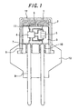
- Figure 1 illustrates in section the ignition device according to the invention.
- reference numeral 1 shows a cup which is usually constructed by a cylindrical body made of a metal.
- Reference numeral 2 denotes ignition charge.
- Reference numeral 3 denotes an ASIC component which is formed by molding with a resin a substrate having elements required for electric circuits such as an ASIC, a capacitor and the like mounted thereon.
- Reference numeral 4 denotes the ASIC, and numeral 5 shows the capacitor.
- the ASIC (application specific integrated circuit) 4 is an integrated circuit for a particular use, which functions as intercommunication switching means in the present invention for igniting the ignition device based on coded information obtained by intercommunicating with the external.
- the capacitor 5 serves as electric energy-accumulating means.
- reference numeral 6 denotes a heating element arranged on the top of the ASIC component 3
- reference numeral 7 denotes communication electrodes arranged at the bottom of the ASIC component 3.
- Reference numeral 8 shows a header made of a metal to which electrode pins 9 are fixed by means of glass to metal sealing 10 for electrically connecting the electric circuits to the external. The electrode pins are fixed by the glass to metal sealing in this manner to ensure electric insulation while maintaining high air-tightness.
- the metal cup and the metal portion of the header are welded to each other to seal the interior of the cup in high air-tightness.
- the ignition charge 2 is arranged at the innermost portion in the cup 1 according to the invention.
- the ignition charge 2 may be of one kind of explosive arranged in a single layer, but as shown in Figure 2 , it is more beneficial to arrange booster charge 2' stronger in inflammation on the outside of the ignition charge 2 so as to form a two-layer structure.
- the booster charge 2' here, it is preferable to contain zirconium in its composition.
- those containing titanium hydride, boron or lead trinitroresorcinate are also advantageously suitable.
- usable ignition charges 2 other than those described above there are, for example, those disclosed in the specification of Japanese Patent Application No.
- Ignition charges are not particularly limited for this purpose.
- the heating element 6 is arranged so as to be in contact with the ignition charge 2.
- the upper surface of the heating element is preferably coated with an ignition charge composition which is beneficial for more stabilizing the contact between the heating element and the ignition charge.
- a so-called SCB chip as such a heating element 6 is favorably suitable, which makes it possible to ignite the powder with low energy. Moreover, it is more advantageous to make such an SCB chip into the form of a bridge structure by laminating metals and insulators because large sparks occur with low energy.
- the "SCB” means a semiconductor bridge which is a heating element produced by the use of the manufacturing process for usual semiconductor integrated circuits.
- a structure formed by alternately laminating titanium and SiO 2 (or boron) on a silicone substrate is advantageously suitable as a preferable bridge structure. Thicknesses of the respective layers are preferably of the order of 0.05 to 10 ⁇ m, and more preferably of 0.1 to 4 ⁇ m.
- an electrical connection of the heating element 6 is effected through ignition electrodes 11 provided on the upper surface of the ASIC component 3.
- the ASIC 4 As means for the intercommunication and triggering particular electric pulse strings, and the capacitor 5 as means for accumulating the electric energy.
- the ASIC component 3 is integrated through the two electrode pins 9 into an air bag system later described which is linked to a local area network (LAN) and communicating with a central control unit.
- LAN local area network
- the ASIC component 3 it is necessary for the ASIC component 3 to be smoothly inserted into the cylindrical cup 1 by forming the ASIC component 3 as a cylindrical shape of a size matching with the inner diameter of the cylindrical cup 1.
- the outer diameter of the ASIC component 3 is preferably of the order of 85 % to 99 % of the inner diameter of the cup.
- the diameter of the communication electrodes 7 arranged at the bottom of the ASIC component 3 is preferably somewhat smaller than the diameter of the electrode pins 9 so that even if contact positions of the communication electrodes 7 and the electrode pins 9 are somewhat shifted to each other owing to assembling errors or the like, these electrodes 7 and the pins 9 can be always maintained in jointed or connected states, thereby enabling the electrical connections between them to be maintained. It is moreover beneficial that the contact portions of the communication electrodes 7 and the electrode pins 9 are flat to ensure stable contact between them when they are strongly pushed to each other.
- the ASIC component 3 is inserted into the cup such that the heating element 6 arranged at the top of the ASIC component 3 abuts against the ignition charge 2. Then, after the header 8 is inserted into the cup 1 such that the electrode pins 9 provided in the header 8 abut against the communication electrodes 7 arranged at the bottom of the ASIC component 3, the header 8 is integrated into the cup 1 by welding to form an integral unit. It is important to perform the welding under the condition that the header 8 has been press-fitted in the cup 1.
- the elastic reaction force of the ASIC component 3 and the cup 1 acts also in the opposite direction so that the heating element 6 provided on the side of the ASIC component 3 opposite from the communication electrodes 7 is jointed to the ignition charge 2 under pressure, that is, to increase the density of the ignition charge 2, thereby achieving reliable ignition and effective shortening of the ignition time.
- the jointing under pressure as described above has advantages that the operation for jointing is simple and easy, and a volume for jointing is hardly required.
- the force for press-fitting the header 8 into the cup 1 is preferably of the order of 1 to 250 MPa. If the force is less than 1 MPa, a pushing force sufficient to joint the communication electrodes 7 and the electrode pins 9 is not obtained, while if the force is more than 250 MPa, the stress applied to the ASIC component becomes too large so that there is a risk of breakage of the ASIC component.
- the more preferable force for press-fitting is 2 to 130 MPa.
- the upper surface of the heating element 6 may be previously coated with the ignition charge composition 2".
- the ignition charge in a slurry state is dispensed or applied to the upper surface of the heating element 6 and then dried.
- the dried ignition charge composition 2" is more stable in the contact with the heating element to effectively contribute to the reliable ignition and shortening of the ignition time.
- a resin cup 12 in the form of a cylindrical sleeve may be provided on the outer circumference of the cup 1. Also, after the header 8 has been press-fitted in the cup 1, the relevant portion may be further molded with resin 13.
- the ASIC component 3 can be arranged in the header 8 and the cup 1 which are held in an airtight state, and further the electrical connection between the communication electrodes 7 and the electrode pins 9 can be kept by the contact between them, so that although the ASIC component 3 is loaded in the device, the overall size of the ignition device 1 can be kept nearly to the sizes of prior art ignition devices.
- the ignition device according to the invention can communicate with the exterior (for example, a central control unit) by the use of the ASIC 4 as intercommunication switching means and the capacitor 5 as electric energy-accumulating means both built in the ASIC component 3.
- coded information used in the intercommunication with the central control unit is intended to mean both the information including a command for igniting each of the ignition devices and the information concerning states of electronic elements included in each of the ignition devices to be transmitted to the central control unit.
- FIG 4 is a conceptual view of a gas generator for an air bag.
- the gas generator 21 for the air bag comprises therein an ignition device 22, an enhancer 23, a gas generant 24, and filters 25, and outside the generator an housing 26 withstanding the pressure when the gas generant 24 is burned.
- the housing 26 is formed with holes 27 for discharging the generated gas into the air bag.
- the enhancer 23 burns by heat energy produced from the ignition device 22 to generate a hot gas by means of which the gas generant 24 is burned to generate a gas for inflating the air bag.
- the generated gas is discharged out of the housing 26 through the holes 27 formed in the housing 26.
- the ignition device according to the invention includes the communication circuit comprising the ASIC, the ignition device is similar in size to the prior art ignition devices as described above. Therefore, the gas generator for an air bag using the ignition device according to the invention is effectively compact and has a size almost similar to sizes of prior art gas generators. Moreover, since the SCB is used as a heating element, ignition occurs in a short period of time so that delay in ignition due to the communication can be prevented.
- FIG. 5 is a conceptual view illustrating the gas generator (micro gas-generator) for a seat belt pretensioner.
- the micro gas-generator 31 comprises therein an ignition device 32 and a gas generant 33.
- the ignition device 32 is fixed to a base 34 called a holder.
- a cup 35 for storing the gas generant 33 therein is also fixed to the holder by means of, for example, caulking.
- the ignition device 32 is actuated, the gas generant 33 in the cup 35 is burned by the heat coming from the ignition device 32 to generate a gas.
- the ignition device according to the invention is compact, although it has the communication circuit comprising the ASIC as described above. Therefore, by using the ignition device, it is also possible to provide the micro gas-generator which is compact and has a size almost similar to sizes of the prior art gas generators. Similarly, by using the SCB as a heating element, ignition occurs in a short period of time so that delay in ignition due to the communication can be prevented.
- the capacitor as electric energy-accumulating means is under a condition accumulating the energy from communication signals sent from the central control unit.
- the central control unit transmits an ignition command in the form of a particular electric pulse string to the ASIC component 3 in the ignition device.
- the ASIC component at this moment the accumulated electric energy is discharged from the capacitor 5 to the heating element 6 by means of the electronic switch.
- the heating element 6 causes the ignition charge 2 to start its ignition with the aid of the electric energy from the capacitor 5.
- Figure 6 illustrates an example of the air bag system linked to a local area network (LAN) and connected with the central control unit 110 and four air bag systems 111a, 111b, 111c and 111d.
- the two air bag modules 111b and 111c each may have a gas generator for inflating, for example, a front air bag, while the other two air bag modules 111a and 111d each may have a gas generator for inflating, for example, a side air bag.
- the ignition device is put in the gas generator included in each of these modules.
- Each of the ignition devices has two electrode pins 114 and 115, the former electrode pins 114 being connected to a first electric-supply conductor 112 connected to the central control unit 110, and the latter electrode pins 115 being connected to a second electric-supply conductor 113 connected to the central control unit 110.
- the central control unit 110 periodically gives the electric-supply conductors 112 and 113 low electric current which is fed through the electrode pins 114 and 115 to the electric energy storing means (capacitors) of the ignition devices included in the four air bag modules 111a, 111b, 111c and 111d, respectively.
- the central control unit 110 feeds a particular electric pulse string constituting an ignition command for the ignition device of the air bag module 111c to the first electric-supply conductor 112.
- the particular electric pulse string is fed to each of the ignition devices through the electrode pins 114 and 115, only the intercommunication means included in the ignition device of the air bag module 111c responds to the command to activate the electric energy-accumulating means associated with the ignition switching means, thereby activating the ignition charge in the manner described above.
- the central control unit 110 gives the first electric-supply conductor 112 a particular electric pulse string for each of the ignition devices included in the air bag modules 111a and 111b, respectively.
- the two ignition devices operate in the same manner as described above.
Landscapes
- Engineering & Computer Science (AREA)
- Computer Hardware Design (AREA)
- Microelectronics & Electronic Packaging (AREA)
- General Engineering & Computer Science (AREA)
- Air Bags (AREA)
- Automotive Seat Belt Assembly (AREA)
- Feeding, Discharge, Calcimining, Fusing, And Gas-Generation Devices (AREA)
Applications Claiming Priority (2)
| Application Number | Priority Date | Filing Date | Title |
|---|---|---|---|
| JP2006001507A JP4813904B2 (ja) | 2006-01-06 | 2006-01-06 | 点火装置およびその製造方法ならびにエアバッグ用ガス発生装置およびシートベルトプリテンショナー用ガス発生装置 |
| PCT/JP2007/050038 WO2007077999A1 (fr) | 2006-01-06 | 2007-01-05 | Allumeur, procede pour le produire, dispositif de production de gaz pour un airbag, et dispositif de production de gaz pour un systeme d'etirage de ceinture de securite |
Publications (2)
| Publication Number | Publication Date |
|---|---|
| EP1970662A1 true EP1970662A1 (fr) | 2008-09-17 |
| EP1970662A4 EP1970662A4 (fr) | 2012-04-04 |
Family
ID=38228335
Family Applications (1)
| Application Number | Title | Priority Date | Filing Date |
|---|---|---|---|
| EP07706385A Withdrawn EP1970662A4 (fr) | 2006-01-06 | 2007-01-05 | Allumeur, procede pour le produire, dispositif de production de gaz pour un airbag, et dispositif de production de gaz pour un systeme d'etirage de ceinture de securite |
Country Status (5)
| Country | Link |
|---|---|
| US (1) | US20090200779A1 (fr) |
| EP (1) | EP1970662A4 (fr) |
| JP (1) | JP4813904B2 (fr) |
| CN (1) | CN101365920A (fr) |
| WO (1) | WO2007077999A1 (fr) |
Families Citing this family (5)
| Publication number | Priority date | Publication date | Assignee | Title |
|---|---|---|---|---|
| JP4996481B2 (ja) * | 2006-01-06 | 2012-08-08 | 日本化薬株式会社 | 点火装置ならびにエアバッグ用ガス発生装置およびシートベルトプリテンショナー用ガス発生装置 |
| JP5285711B2 (ja) * | 2008-11-05 | 2013-09-11 | 日本化薬株式会社 | 点火システムならびにエアバッグ用ガス発生装置およびシートベルトプリテンショナー用ガス発生装置 |
| CN104296602A (zh) * | 2014-10-13 | 2015-01-21 | 北京理工北阳爆破工程技术有限责任公司 | Pcb型低电压半导体桥发火组件 |
| JP6781072B2 (ja) * | 2017-02-24 | 2020-11-04 | 日本化薬株式会社 | 点火器および当該点火器を備えるガス発生器 |
| CN116147424B (zh) * | 2022-12-26 | 2025-07-04 | 重庆云铭科技股份有限公司 | 一种非敏感型火工品换能元结构 |
Family Cites Families (21)
| Publication number | Priority date | Publication date | Assignee | Title |
|---|---|---|---|---|
| US5912427A (en) * | 1993-02-26 | 1999-06-15 | Quantic Industries, Inc. | Semiconductor bridge explosive device |
| FR2704944B1 (fr) * | 1993-05-05 | 1995-08-04 | Ncs Pyrotechnie Technologies | Initiateur électro-pyrotechnique. |
| FR2720493B1 (fr) * | 1994-05-31 | 1996-07-19 | Giat Ind Sa | Initiateur pyrotechnique. |
| US5889228A (en) * | 1997-04-09 | 1999-03-30 | The Ensign-Bickford Company | Detonator with loosely packed ignition charge and method of assembly |
| US6096997A (en) * | 1997-08-29 | 2000-08-01 | Trw Inc. | Method of assembling an igniter including infrared testing of heating element and welds |
| US6166452A (en) * | 1999-01-20 | 2000-12-26 | Breed Automotive Technology, Inc. | Igniter |
| US6848365B2 (en) * | 2000-12-08 | 2005-02-01 | Special Devices, Inc. | Initiator with an internal sleeve retaining a pyrotechnic charge and methods of making same |
| JP4811975B2 (ja) * | 2001-06-06 | 2011-11-09 | 日本化薬株式会社 | 着火薬組成物、及びその着火薬組成物を用いた点火具 |
| US7168737B2 (en) * | 2002-01-25 | 2007-01-30 | Daicel Chemical Industries, Ltd. | Integrated circuit for air bag system |
| US6820557B2 (en) * | 2002-01-25 | 2004-11-23 | Daicel Chemical Industries, Ltd. | Igniter for air bag system |
| JP3803636B2 (ja) * | 2002-12-26 | 2006-08-02 | 本田技研工業株式会社 | バス接続用点火装置 |
| JP4094529B2 (ja) * | 2003-11-10 | 2008-06-04 | 本田技研工業株式会社 | 着火装置 |
| US7343859B2 (en) * | 2003-11-10 | 2008-03-18 | Honda Motor Co., Ltd. | Squib |
| JP4335725B2 (ja) * | 2004-03-30 | 2009-09-30 | 日本化薬株式会社 | ガス発生器 |
| JP4444717B2 (ja) * | 2004-04-07 | 2010-03-31 | 本田技研工業株式会社 | 着火装置 |
| JP4397731B2 (ja) * | 2004-05-12 | 2010-01-13 | 日本化薬株式会社 | 点火装置 |
| JP4633522B2 (ja) * | 2005-04-05 | 2011-02-16 | ダイセル化学工業株式会社 | 点火器組立体 |
| JP4996481B2 (ja) * | 2006-01-06 | 2012-08-08 | 日本化薬株式会社 | 点火装置ならびにエアバッグ用ガス発生装置およびシートベルトプリテンショナー用ガス発生装置 |
| JP4705550B2 (ja) * | 2006-10-26 | 2011-06-22 | 日本化薬株式会社 | スクイブならびにエアバッグ用ガス発生装置およびシートベルトプリテンショナー用ガス発生装置 |
| JP4714669B2 (ja) * | 2006-12-01 | 2011-06-29 | 日本化薬株式会社 | ヘッダーアッシー、スクイブならびにエアバッグ用ガス発生装置およびシートベルトプリテンショナー用ガス発生装置 |
| JP4916868B2 (ja) * | 2006-12-20 | 2012-04-18 | 株式会社ダイセル | 電気的な着火を利用する装置の組立方法 |
-
2006
- 2006-01-06 JP JP2006001507A patent/JP4813904B2/ja not_active Expired - Fee Related
-
2007
- 2007-01-05 EP EP07706385A patent/EP1970662A4/fr not_active Withdrawn
- 2007-01-05 CN CNA2007800018959A patent/CN101365920A/zh active Pending
- 2007-01-05 US US12/159,881 patent/US20090200779A1/en not_active Abandoned
- 2007-01-05 WO PCT/JP2007/050038 patent/WO2007077999A1/fr not_active Ceased
Also Published As
| Publication number | Publication date |
|---|---|
| EP1970662A4 (fr) | 2012-04-04 |
| JP2007183042A (ja) | 2007-07-19 |
| US20090200779A1 (en) | 2009-08-13 |
| CN101365920A (zh) | 2009-02-11 |
| WO2007077999A1 (fr) | 2007-07-12 |
| JP4813904B2 (ja) | 2011-11-09 |
Similar Documents
| Publication | Publication Date | Title |
|---|---|---|
| JP3463263B2 (ja) | 点火装置 | |
| EP2077430A1 (fr) | Amorce, dispositif de génération de gaz pour coussin de sécurité gonflable et dispositif de génération de gaz pour prétendeur de ceinture de sécurité | |
| EP1383664A2 (fr) | Generateur de gaz | |
| CN101772689A (zh) | 点火装置以及气囊用气体产生装置及安全带预紧器用气体产生装置 | |
| EP2351980B1 (fr) | Système d'allumage, dispositif de génération de gaz pour un airbag et dispositif de génération de gaz pour un prétendeur de ceinture de sécurité | |
| EP2093533B1 (fr) | Ensemble collecteur, amorce, dispositif de production de gaz pour sac gonflable et dispositif de production de gaz pour prétensionneur de ceinture de sécurité | |
| US8074571B2 (en) | Apparatus including igniter | |
| EP1970662A1 (fr) | Allumeur, procede pour le produire, dispositif de production de gaz pour un airbag, et dispositif de production de gaz pour un systeme d'etirage de ceinture de securite | |
| US20040123765A1 (en) | Initiator and gas generator | |
| EP1970663A1 (fr) | Dispositif de mise a feu, dispositif de production de gaz pour un airbag, et dispositif de production de gaz pour un dispositif d'etirage de ceinture de securite | |
| US20040250542A1 (en) | Gas generator | |
| EP3134298B1 (fr) | Initiateurs de montage en surface | |
| JP4914193B2 (ja) | スクイブならびにエアバッグ用ガス発生装置およびシートベルトプリテンショナー用ガス発生装置 | |
| JP2005326041A (ja) | 点火装置 |
Legal Events
| Date | Code | Title | Description |
|---|---|---|---|
| PUAI | Public reference made under article 153(3) epc to a published international application that has entered the european phase |
Free format text: ORIGINAL CODE: 0009012 |
|
| 17P | Request for examination filed |
Effective date: 20080626 |
|
| AK | Designated contracting states |
Kind code of ref document: A1 Designated state(s): CZ DE FR |
|
| RBV | Designated contracting states (corrected) |
Designated state(s): CZ DE FR |
|
| A4 | Supplementary search report drawn up and despatched |
Effective date: 20120301 |
|
| RIC1 | Information provided on ipc code assigned before grant |
Ipc: B60R 21/017 20060101ALI20120224BHEP Ipc: F42B 3/12 20060101AFI20120224BHEP Ipc: F42B 3/13 20060101ALN20120224BHEP |
|
| DAX | Request for extension of the european patent (deleted) | ||
| STAA | Information on the status of an ep patent application or granted ep patent |
Free format text: STATUS: THE APPLICATION IS DEEMED TO BE WITHDRAWN |
|
| 18D | Application deemed to be withdrawn |
Effective date: 20121002 |