EP1970799A2 - Dispositif électronique et son procédé de contrôle de mode et terminal de communication mobile - Google Patents
Dispositif électronique et son procédé de contrôle de mode et terminal de communication mobile Download PDFInfo
- Publication number
- EP1970799A2 EP1970799A2 EP08003122A EP08003122A EP1970799A2 EP 1970799 A2 EP1970799 A2 EP 1970799A2 EP 08003122 A EP08003122 A EP 08003122A EP 08003122 A EP08003122 A EP 08003122A EP 1970799 A2 EP1970799 A2 EP 1970799A2
- Authority
- EP
- European Patent Office
- Prior art keywords
- screen
- function
- area
- operating mode
- input
- Prior art date
- Legal status (The legal status is an assumption and is not a legal conclusion. Google has not performed a legal analysis and makes no representation as to the accuracy of the status listed.)
- Granted
Links
Images








Classifications
-
- G—PHYSICS
- G06—COMPUTING OR CALCULATING; COUNTING
- G06F—ELECTRIC DIGITAL DATA PROCESSING
- G06F3/00—Input arrangements for transferring data to be processed into a form capable of being handled by the computer; Output arrangements for transferring data from processing unit to output unit, e.g. interface arrangements
- G06F3/01—Input arrangements or combined input and output arrangements for interaction between user and computer
- G06F3/048—Interaction techniques based on graphical user interfaces [GUI]
- G06F3/0487—Interaction techniques based on graphical user interfaces [GUI] using specific features provided by the input device, e.g. functions controlled by the rotation of a mouse with dual sensing arrangements, or of the nature of the input device, e.g. tap gestures based on pressure sensed by a digitiser
- G06F3/0488—Interaction techniques based on graphical user interfaces [GUI] using specific features provided by the input device, e.g. functions controlled by the rotation of a mouse with dual sensing arrangements, or of the nature of the input device, e.g. tap gestures based on pressure sensed by a digitiser using a touch-screen or digitiser, e.g. input of commands through traced gestures
- G06F3/04883—Interaction techniques based on graphical user interfaces [GUI] using specific features provided by the input device, e.g. functions controlled by the rotation of a mouse with dual sensing arrangements, or of the nature of the input device, e.g. tap gestures based on pressure sensed by a digitiser using a touch-screen or digitiser, e.g. input of commands through traced gestures for inputting data by handwriting, e.g. gesture or text
-
- G—PHYSICS
- G06—COMPUTING OR CALCULATING; COUNTING
- G06F—ELECTRIC DIGITAL DATA PROCESSING
- G06F3/00—Input arrangements for transferring data to be processed into a form capable of being handled by the computer; Output arrangements for transferring data from processing unit to output unit, e.g. interface arrangements
- G06F3/01—Input arrangements or combined input and output arrangements for interaction between user and computer
- G06F3/048—Interaction techniques based on graphical user interfaces [GUI]
- G06F3/0487—Interaction techniques based on graphical user interfaces [GUI] using specific features provided by the input device, e.g. functions controlled by the rotation of a mouse with dual sensing arrangements, or of the nature of the input device, e.g. tap gestures based on pressure sensed by a digitiser
- G06F3/0488—Interaction techniques based on graphical user interfaces [GUI] using specific features provided by the input device, e.g. functions controlled by the rotation of a mouse with dual sensing arrangements, or of the nature of the input device, e.g. tap gestures based on pressure sensed by a digitiser using a touch-screen or digitiser, e.g. input of commands through traced gestures
- G06F3/04886—Interaction techniques based on graphical user interfaces [GUI] using specific features provided by the input device, e.g. functions controlled by the rotation of a mouse with dual sensing arrangements, or of the nature of the input device, e.g. tap gestures based on pressure sensed by a digitiser using a touch-screen or digitiser, e.g. input of commands through traced gestures by partitioning the display area of the touch-screen or the surface of the digitising tablet into independently controllable areas, e.g. virtual keyboards or menus
Definitions
- This document relates to an electronic device, a method of controlling a mode thereof, a computer program product and a mobile communication terminal.
- portable electronic devices may have various additional functions including a personal information management function such as a phone book, and a scheduler, and a multimedia function such as transmission and reception of a moving picture and an image mail as well as a function as a personal mobile communication appliance.
- a personal information management function such as a phone book, and a scheduler
- a multimedia function such as transmission and reception of a moving picture and an image mail as well as a function as a personal mobile communication appliance.
- a computer program product and a method of controlling an operating mode of an electronic device comprising: receiving a control signal for controlling a predetermined area; and controlling a size and an operating mode of a screen by the control signal.
- an electronic device comprising: a display unit for displaying a screen; an input unit; and a controller for receiving a control signal from the input unit to control a size and an operating mode of the screen displayed in the display unit by the control signal.
- a mobile communication terminal comprising: a radio frequency (RF) module for performing wireless communication; a memory for storing various programs for providing a wireless communication function and an additional function; a display unit for displaying a screen by program execution; an input unit for outputting a control signal by user input; and a controller for controlling a size and an operating mode of a screen displayed in the display unit by the control signal input through the input unit.
- RF radio frequency
- a computer program product and a method of controlling input/output comprising: receiving a plurality of touch signals; and controlling a size of a display area by the plurality of touch signals.
- an input/output control device comprising: a display unit for displaying a screen; an input unit for outputting a selection signal and a slide signal that are input by a user with a touch signal; and a controller for controlling a size of a display area selected by a plurality of touch signals in the display unit, by the plurality of touch signals that is input through the input unit.
- a mobile communication terminal comprising: an RF module for performing wireless communication; a memory for storing various programs for providing a wireless communication function and an additional function; a display unit for displaying a screen by program execution; an input unit for outputting a selection signal and a slide signal input by a user to a touch signal; and a controller for controlling a size of a display area selected by a plurality of touch signals in the display unit, by the plurality of touch signals that is input through the input unit.
- FIG. 1 is a block diagram illustrating a configuration of an electronic device in an implementation
- FIG. 2 is a diagram illustrating a converting process of an operating mode of an electronic device in an implementation
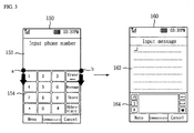
- FIG. 3 is a diagram illustrating a converting process of an operating mode of an electronic device in another implementation
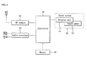
- FIG. 4 is a block diagram illustrating a configuration of a mobile communication terminal in an implementation
- FIG. 5 is a diagram illustrating a converting process of an operating mode of a mobile communication terminal in an implementation
- FIG. 6 is a diagram illustrating a converting process of an operating mode of a mobile communication terminal in another implementation
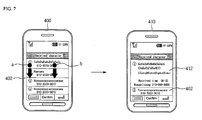
- FIG. 7 is a diagram illustrating a converting process of an operating mode of a mobile communication terminal in another implementation
- FIG. 8 is a diagram illustrating a converting process of an operating mode of a mobile communication terminal in another implementation
- FIG. 9 is a block diagram illustrating a configuration of an input/output control device in another implementation.
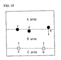
- FIG. 10 is a diagram illustrating an input process of an input/output control device in another implementation
- FIG. 11 is a diagram illustrating an input process of an input/output control device in another implementation
- FIG. 12 is a diagram illustrating an input process of an input/output control device in another implementation
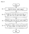
- FIG. 13 is a flowchart of a method of controlling input/output in another implementation
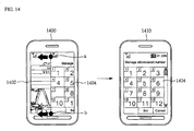
- FIG. 14 is a diagram illustrating a display process of a mobile communication terminal in another implementation
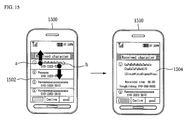
- FIG. 15 is a diagram illustrating an input/output process of a mobile communication terminal in another implementation.
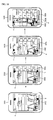
- FIG. 16 is a diagram illustrating an input/output process of a mobile communication terminal in another implementation.
- FIG. 1 is a block diagram illustrating a configuration of an electronic device in an implementation.
- the electronic device comprises a user input unit 2 for performing user input, a display unit 4 for displaying a screen, a memory 6 for storing programs and data for executing various functions, and a controller 8 for receiving a control signal for selecting a predetermined area of the display unit 4 through the user input unit 2 to control a screen size of the corresponding area and an operating mode of the corresponding screen.
- the user input unit 2 can use a key input means such as a keypad, a menu key, a direction key, and a side (or upper and lower) key, and a user input sensor such as a touch sensor, a distance sensor, and a geomagnetic sensor. Further, the user input unit 2 may be embodied in a form of a touch screen using a touch panel for detecting user touch.
- a key input means such as a keypad, a menu key, a direction key, and a side (or upper and lower) key
- a user input sensor such as a touch sensor, a distance sensor, and a geomagnetic sensor.
- the user input unit 2 may be embodied in a form of a touch screen using a touch panel for detecting user touch.
- the display unit 4 may provide various images such as user input, a menu, and an operating state of the electronic device, and displays a plurality of divided screens according to an operating state of the electronic device.
- the display unit 4 may use a display device such as a liquid crystal display (LCD), a plasma display panel (PDP), and an organic light emitting diode (OLED).
- LCD liquid crystal display
- PDP plasma display panel
- OLED organic light emitting diode
- the controller 8 recognizes an area selected by the user and a slide direction of a user's sliding touch by processing a user control signal that is input through the user input unit 2, enlarges or reduces a size of the area selected by the user in the slide direction according to a recognition result, converts an operating mode of the corresponding area to another operating mode, and displays the converted operating mode in the display unit 4.
- the controller 8 can display a plurality of divided screens in the display unit 4. Accordingly, the controller 8 controls a size of a screen selected by the user, converts an operating mode of the corresponding screen to a preset operating mode, and controls the display of the corresponding screen.
- Conversion of an operating mode of a screen indicates the change of a display state, an operating state, and an input/output attribute of a current screen. For example, as the operating mode of the screen is converted from a phone number display mode to a character message display mode, when information displayed on the screen is changed, a display state on the screen is changed, whereby it is determined that an operating mode is converted.
- an input operating state on a touch screen is changed, whereby it is determined that an operating mode is converted.
- a conversion order of the converting operating mode is set upon designing a system or is directly set by the user.
- the conversion order of the operating mode upon designing a system is set to be converted to a mode having correlation according to characteristics of each operating mode, is set to be converted to a mode interlocked to an operating mode of a screen that is not selected, and is set so that operating modes of currently displaying screens to be converted to each other.
- the controller 8 executes a preset program, thereby controlling an execution screen of the corresponding program to be displayed at a position in which a touch signal is input, and thus displays both the displaying screen and a screen that is executed by inputting a touch signal with a divided screen.
- FIG. 2 is a diagram illustrating a converting process of an operating mode of an electronic device in an implementation.
- a control signal by sliding two points 'a' and 'b' toward the 'A' mode operation screen.
- the user can use the side key and the direction key, and upon using the touch panel 12, after selecting by touching the corresponding points 'a' and 'b' of the first display screen 100, the user slides the points 'a' and 'b', thereby inputting a control signal.
- the controller 8 enlarges an area of the 'B' mode operation screen in a slide direction, converts the 'B' mode operation screen to a 'C' mode operation screen, and displays the 'C' mode operation screen.
- a display state of the first display screen 100 is converted to a state in which both the 'A' mode operation screen and the 'C' mode operation screen are displayed.
- the 'B' mode and the 'C' mode may be a mode having a functional correlation.
- both modes are modes belonging to an input menu
- the 'B' mode is a picture album viewing mode and the 'C' mode is a moving picture album viewing mode
- both modes are modes belonging to an album menu.
- the 'C' mode operation screen can be converted to an operating mode related to the 'A' mode operation screen that is not selected.
- a border of two screens is fixed at points 'e' and 'f', and operating modes of two screens can be converted to a 'D' mode operation screen and an 'E' mode operation screen.
- the previous example is a case of controlling a size and an operating mode of an area using two user control signals.
- a size and an operating mode of a selection area can be changed through the same process.
- FIG. 3 is a diagram illustrating a converting process of an operating mode of an electronic device in another implementation, and shows a case of receiving a control signal from the user through a touch screen to change a size and an operation state of the screen.
- both a numeral input screen 154 for inputting a sending phone number and a numeral display screen 152 for displaying a selected sending phone number are displayed on a first touch screen 150.
- the user After selecting by touching two points 'a' and 'b' around a boundary line between the numeral display screen 152 and the numeral input screen 154, the user can input a control signal by sliding the two points 'a' and 'b' toward the numeral input screen 154.
- the controller 8 moves a boundary line between the screens in a slide direction, and converts operating states of the numeral display screen 152 and the numeral input screen 154, thereby displaying a second touch screen 160.
- Both a character input screen 164 for inputting a message and a character display screen 162 for displaying the input character are displayed on the second touch screen 160 in which both a size and an operating mode of the screen are converted. Accordingly, both screen sizes and operating modes of a touch screen operating in a different operating mode on the divided screen can be converted through simple touch and slide operation.
- FIG. 4 is a block diagram illustrating a configuration of a mobile communication terminal in an implementation.
- the mobile communication terminal comprises a radio frequency (RF) module 22 for performing wireless transmission and reception, an audio processor 24 for processing an audio signal that is input and output through a microphone MIC and a speaker SPK, a memory 16 for storing program and user data, a touch screen 20 for performing user input and screen display, and a controller 18 for controlling general functions of the mobile communication terminal.
- RF radio frequency
- the touch screen 20 comprises a display unit 14 for displaying data and a touch panel 12, which is a transparent panel having a touch response surface, that is mounted on a visible surface of the display unit 14.
- the display unit 14 user input, a state of the mobile communication terminal, and a processing screen according to execution of a function of the mobile communication terminal are displayed.
- the display unit 14 can use a display device such as an LCD, PDP, and OLED.
- the touch panel 12 detects a touch signal that is input by the user, recognizes a selection position and a selection direction of the touch signal, and provides an input signal such as a control signal and a slide signal to the controller 18.
- the touch panel 12 can be embodied by using various technology such as a resistance method, a capacitance method, an infrared ray method, a surface acoustic wave (SAW) method, an electromagnetic method, and a Near Field Imaging (NFI) method.
- program data and driving setting data for provided various functions of the mobile communication terminal are stored.
- setting information of an operating mode that is converted by user selection is stored.
- the controller 18 controls general function execution of the mobile communication terminal by executing a program that is stored in the memory 16 by a touch signal that is input through the touch screen 20, and provides generated graphic data to the display unit 14, thereby controlling a text and an image to be displayed on a screen.
- the controller 18 controls a screen of the display unit 14 to be displayed with a plurality of divided screens, thereby controlling a screen corresponding to each function to be displayed.
- the controller 18 processes a control signal that is input through the touch screen 20 to an area control signal and a slide signal, recognizes a display area of the display unit 14 selected by the user, and enlarges or reduces a size of a display area in a moving direction of the slide signal. Further, the controller 18 controls an operating mode of the selected area to be converted to a different operating mode according to an operating mode setting information that is stored in the memory 16.
- the controller 18 executes an execution program of the corresponding operating mode, controlling a screen of the operating mode to be displayed with a divided screen at a position selected by the user.
- FIG. 5 is a diagram illustrating a converting process of an operating mode of a mobile communication terminal in an implementation, and shows a case of newly generating and displaying a screen by a control signal that is input by the user.
- a new number registration screen 202 is displayed on the display screen 200 by the control of the controller 18.
- the controller 18 executes a preset function, thereby controlling an operation mode screen for performing the corresponding function to be displayed at a point selected by the user.
- a keypad input menu necessary for user input is executed, and thus both a new number registration screen 212 and a keypad input screen 214 are displayed on the display screen 210.
- FIG. 6 is a diagram illustrating a converting process of an operating mode of a mobile communication terminal in another implementation.
- Both a new number registration screen 302 and a keypad input screen 304 can be simultaneously displayed on a divided screen on a display screen 300 of the mobile communication terminal in another implementation.
- the user can select by touching a predetermined point of the keypad input screen 304, and slide the predetermined point in a vertical direction.
- the controller 18 controls the keypad input screen 304 to be reduced in a slide direction and the keypad input screen 304 to be converted to a different mode screen.
- the controller 18 can execute a touch input mode, which is an input menu similar to a keypad input mode. Accordingly, a new number registration screen 312 is displayed on the display screen 310, the original keypad input screen 304 is converted to a touch input screen 314, and the touch input screen 314 is displayed.
- the touch input screen 314 is reduced by a slide signal of the user to be displayed in an area smaller than the keypad input screen 304 that has originally been displayed.
- the controller 18 controls to the touch input screen 314 to be converted to another mode screen.
- the controller 18 can execute a multiple touch input mode, which is an input mode similar to the touch input mode.
- a new number registration screen 322 is displayed on the display screen 320, the original touch input screen 314 is converted to a multiple touch input screen 324, and the multiple touch input screen 324 is displayed.
- the multiple touch input screen 324 can be displayed in an area larger or smaller than the touch input screen 314 that has been previously displayed in a direction of a slide signal input by the user.
- FIG. 7 is a diagram illustrating a converting process of an operating mode of a mobile communication terminal in another implementation.
- a received message list 402 can be displayed on the display screen 400 of the mobile communication terminal in another implementation.
- a sender or sending number, sending time, and some content of each message are displayed in the received message list 402.
- the controller 18 enlarges an area of the corresponding message by a user's control signal, and converts an operating mode of the corresponding area from the received message list display mode to a massage content display mode.
- the received message list 402 and the message display screen 412 are displayed on the display screen 410, and thus the user can check a desired message content in the received message list 402. Accordingly, other messages displayed in the received message list 402 can be also easily checked.
- FIG. 8 is a diagram illustrating a converting process of an operating mode of a mobile communication terminal in another implementation.
- the display screen 420 of the mobile communication terminal in another implementation is operated in a single mode, the display screen 420 displays only a message display screen 422 for displaying a content of the received message.
- the controller 18 executes a preset function, thereby controlling an operating mode screen for using the corresponding function to be displayed. For example, when a touch signal and a slide signal are input on the message display screen 422, the controller 18 can execute a character message input function for inputting a reply message to send to a sender of a currently displaying message.
- both a character input screen 434 for inputting a message and a character display screen 432 for displaying the input character are displayed on the display screen 430, whereby the user can input a reply message to send to another party of the checked message.
- FIG. 9 is a block diagram illustrating a configuration of an input/output control device in an implementation.
- the input/output control device comprises an input unit 910 for processing a touch signal that is input by the user, a display unit 920 for displaying a screen, and a controller 930 for controlling a screen displayed in the display unit 920 according to a plurality of touch signals that is input through the input unit 910.
- the input unit 910 comprises a touch panel 912 for detecting user touch and an input processor 914 for recognizing a selection position and a selection direction of a touch signal detected in the touch panel 912 and providing an input signal such as a selection signal and a slide signal to the controller 930.
- the touch panel 912 can detect a touch signal selected at a predetermined point such as points 'a' and 'b' and can be embodied using various technology such as a resistance method, a capacitance method, an infrared ray method, a SAW method, an electromagnetic method, and an NFI method.
- the touch panel 912 is a transparent panel having a touch response surface and is mounted on a visible surface, for example, an LCD 922 of the display unit 920.
- a touch signal detected by the input unit 910 comprises a selection signal for selecting a predetermined point and a slide signal having directionality and moving to a predetermined direction.
- the input processor 914 receives a touch signal from the touch panel 912 and processes information such as an input position and a moving direction of the signal and provides the information to the controller 930.
- the display unit 920 comprises an LCD 922 for providing an image and an image processor 924 for converting a data signal provided from the controller 930 to a video signal to be displayed on the LCD 922 and displaying the video signal on the LCD 922.
- the display unit 920 can use a display device such as an LCD, PDP, and OLED.
- the display unit 920 and the input unit 910 have a form of a touch screen for mounting the touch panel 912 on a visible surface of the LCD 922 or are formed in a form of a touch pad in a predetermined area separated from an installation area of the display unit 920, thereby performing an input and output function by the user.
- the controller 930 recognizes a display area of the display unit 920 selected by a plurality of touch signals that is input through the input unit 910 and enlarges or reduces a size of a display area in a moving direction of a touch signal.
- the controller 930 displays a plurality of divided screens in the display unit 920 and recognizes a selected display area by a plurality of touch signals that is input around a boundary line between the screens.
- the touch signal comprises a selection signal for selecting a point and a slide signal having directionality and moving to a predetermined direction, and thus the controller 930 controls the display unit 920 so that a boundary line between the screens moves in a slide direction of the slide signal, thereby enlarging or reducing the selected display area.
- the controller 930 recognizes the selected display area even in a case where a plurality of touch signals comprising a selection signal and a slide signal is input, thereby enlarging or reducing the display area.
- the controller 930 enlarges and displays the displayed information when a display area is enlarged and reduces and displays the displayed information when a display area is reduced.
- the controller 930 controls an execution screen of the corresponding program to be displayed at a position in which the selection signal is input by executing a preset program, thereby controlling a currently displaying screen and a screen executed by the input of a selection signal to be displayed as a divided screen.
- the input/output processor recognizes that an area is selected by a plurality of touch signals generating in a boundary line between screens, thereby improving a recognition rate of a touch signal.
- FIGS. 10 to 12 show a case of embodying the input/output control device of FIG. 9 in a form of a touch screen, and show a state of providing the touch panel 912 on the LCD 922 of the display unit 920 and controlling a screen by a plurality of touch signals.
- FIG. 10 is a diagram illustrating an input process of an input/output control device in an implementation, and shows a case of displaying 3 screens in areas 'A', 'B', and 'C' on a touch screen.
- the user selects by touching two points 'a' and 'b' around a boundary line between the areas B' and 'C' and slides two points 'a' and 'b' toward the area 'B'.
- the controller 930 recognizes that a boundary line between the areas 'B' and 'C' is selected through a position of points 'a' and 'b' to which a touch signal is input and controls a display area of an area 'C' to be enlarged by moving and displaying the boundary line in a slide direction. Touch signals generating at the points 'a' and 'b' can be generated at the same time.
- the controller 930 moves a boundary line between the selected screens in a slide direction by processing the operations with a signal of controlling a screen size, thereby controlling a display area of the area 'C' to be enlarged and a display area of the area 'B' to be reduced.
- the controller 930 recognizes the selected area, thereby controlling a screen size to be adjusted. For example, the user can sequentially touch points 'c', 'd', and 'e' around a boundary line between the areas 'A' and 'B' and slide only the selected point 'e' toward the area 'B'.
- the controller 930 recognizes that a boundary line between the areas 'A' and 'B' is selected through a position of the points 'c', 'd', and 'e' to which a touch signal is input and moves and displays a boundary line in a slide direction at the point 'e', thereby enlarging a display area of the area 'A'.
- FIG. 11 is a diagram illustrating an input process of an input/output control device in an implementation, and shows a case of displaying two screens of areas 'A' and B' on a touch screen.
- the user can select by sliding touching a section from a point 'a' to a point 'b' around a boundary line between the areas 'A' and 'B' and slide the section toward the area 'A'. Accordingly, the controller 930 recognizes that a boundary line between the areas 'A' and 'B' is selected through a position of the sliding section from the point 'a' to the point 'b' and moves and displays a boundary line in a slide direction at the point 'b', thereby enlarging a display area of the area 'B'.
- FIG. 12 is a diagram illustrating an input process of an input/output control device in an implementation, and shows a case of displaying two screens of areas 'A' and 'B' on the touch screen.
- the user can adjust a size of a display area by selecting a predetermined point of an area to control.
- a predetermined point of an area to control In order to controls a size of a display area of the area 'B', the user can select by touching a predetermined point, for example, points 'a' and 'b' within the area 'B' and slides the predetermined point toward the area 'A'.
- the controller 930 recognizes that the area 'B' is selected through a position of the points 'a' and 'b' to which a touch signal is input, and moves and displays a boundary line in a slide direction, thereby controlling a display area of the area 'B' to be enlarged.
- a touch signal generating at the points 'a' and 'b' may be a signal generating at the same time.
- the controller 930 moves a boundary line between the selected screens in a slide direction by processing the operations with a signal of adjusting a screen size, thereby controlling a display area of the area 'B' to be enlarged and a display area of the are 'A' to be reduced.
- FIG. 13 is a flowchart of a method of controlling input/output in an implementation.
- the controller 930 receives a plurality of touch signals selected by the user through the touch panel 912 of the input unit 910 (S1).
- the plurality of touch signals may be input simultaneously or continuously at different positions.
- the continuously input touch signal may be input by continuously selecting almost adjacent areas or by sequentially selecting different positions.
- the controller 930 recognizes a selected area according to an input position of each touch signal (S3).
- the controller 930 accurately recognizes an area selected by the user by recognizing a border area between screens at a position adjacent to a plurality of touch signals.
- the controller 930 checks a slide direction of a touch signal (S5), and controls the display unit 920 to enlarge or reduce a screen area selected by the touch signal in a slide direction (S7).
- a display area is enlarged by a touch signal
- the controller 930 controls data displayed in the corresponding area to be enlarged and displayed
- a display area is reduced by a touch signal
- the controller 930 controls data displayed in the corresponding area to be reduced and displayed.
- a plurality of touch signals can be generated even in an area in which only one screen is displayed in the display unit 920 or even in an area relatively far apart from a border area between screens.
- the controller 930 executes a preset function, thereby controlling a screen of the corresponding function to be displayed with a divided screen at a position selected by the user.
- FIG. 14 is a diagram illustrating a display process of a mobile communication terminal in another implementation, and shows a case of displaying divided screens in the display unit 14 by executing a plurality of menus at the same time.
- Both a schedule display screen 1402 according to execution of a predetermined function and an abbreviated number management screen 1404 can be displayed on each of divided screens on a display screen 1400 of the mobile communication terminal in another implementation.
- the user can select by touching points 'a' and 'b' around a border between the schedule display screen 1402 and the abbreviated number management screen 1404 and slide the points 'a' and 'b' in a direction enlarging an area of the abbreviated number management screen 1404.
- the controller 18 recognizes that the points 'a' and 'b' are positioned around a border between the schedule display screen 1402 and the abbreviated number management screen 1404 and enlarges the abbreviated number management screen 1404 in a slide direction, thereby controlling the entire abbreviated number management screen 1404 to be displayed on the display screen 1410.
- a touch signal for selecting and sliding the points 'a' and 'b' can be input at the same time or can be input by sequentially inputting the points 'a' and 'b' and sliding only any one of touch signals of the points 'a' and 'b'.
- the controller 18 controls an extension distance of a screen to be in proportion to an input distance of a slide signal, thereby providing convenience to the user. For example, if the user selects the points 'a' and 'b' and slides the points 'a' and 'b' up to the end of the display screen 1410 in a horizontal direction, the abbreviated number management screen 1404 is displayed in a full screen on the display screen 1410. When an end point of a slide input stops at a predetermined point, the abbreviated number management screen 1404 can be enlarged only up to a stop point of the slide input.
- FIG. 15 is a diagram illustrating an input/output process of a mobile communication terminal in another implementation, and shows a case of providing data in a list or a table.
- the received message list 1502 can be displayed on a display screen 1500 of the mobile communication terminal in another implementation.
- a sender or a sending phone number, a sending time, and some content of each message are displayed.
- the user can select by touching points 'a' and 'b' of the corresponding message area of the received message list 1502, and slide the points 'a' and 'b' in a direction enlarging an area of the corresponding message.
- the controller 18 recognizes a selected message through a position of the points 'a' and 'b' and displays the received message list 1504 having an enlarged area in a slide direction on the display screen 1510, thereby controlling to check a content of the received message on the received message list 1504.
- FIG. 16 is a diagram illustrating an input/output process of a mobile communication terminal in another implementation, and shows a case of newly generating and displaying a screen by a plurality of touch signals that is input by the user.
- the controller 18 executes a preset function, thereby controlling a display screen 1610 so that the corresponding function screen is displayed at a point selected by the user.
- a case of executing an abbreviated number management function is described, and a case of displaying the abbreviated number management screen 1604 at the points 'a' and 'b' selected by the user is described.
- the controller 18 executes a preset function, thereby controlling a display screen 1630 so that the corresponding function screen is displayed at a point selected by the user.
- FIGS. 14 and 16 a case of executing a calendar viewing function is described, and a case of displaying a calendar screen 1606 at the points 'c' and 'd' selected by the user is described.
- the device which includes one or more of the previously described embodiments may be a portable cell phone configured to communicate with another cell phone directly or via a base station or related intermediary.
- the device includes an antenna and a communication input/output device.
- the device may also be a PDA or another portable terminal device.
- Various embodiments described herein may be implemented in a computer-readable medium using, for example, computer software, hardware, or some combination thereof.
- the embodiments described herein may be implemented within one or more application specific integrated circuits (ASICs), digital signal processors (DSPs), digital signal processing devices (DSPDs), programmable logic devices (PLDs), field programmable gate arrays (FPGAs), processors, controllers, micro-controllers, microprocessors, other electronic units designed to perform the functions described herein, or a selective combination thereof.
- ASICs application specific integrated circuits
- DSPs digital signal processors
- DSPDs digital signal processing devices
- PLDs programmable logic devices
- FPGAs field programmable gate arrays
- processors controllers, micro-controllers, microprocessors, other electronic units designed to perform the functions described herein, or a selective combination thereof.
- the embodiments described herein may be implemented with separate software modules, such as procedures and functions, each of which perform one or more of the functions and operations described herein.
- the software codes can be implemented with a software application written in any suitable programming language and may be stored in memory, and executed by a controller or processor.
Landscapes
- Engineering & Computer Science (AREA)
- General Engineering & Computer Science (AREA)
- Theoretical Computer Science (AREA)
- Human Computer Interaction (AREA)
- Physics & Mathematics (AREA)
- General Physics & Mathematics (AREA)
- User Interface Of Digital Computer (AREA)
- Telephone Function (AREA)
- Selective Calling Equipment (AREA)
Applications Claiming Priority (2)
| Application Number | Priority Date | Filing Date | Title |
|---|---|---|---|
| KR1020070025577A KR101370173B1 (ko) | 2007-03-15 | 2007-03-15 | 입출력 제어장치 및 입출력 제어방법과 그를 이용한이동통신단말기 |
| KR1020070025580A KR101354820B1 (ko) | 2007-03-15 | 2007-03-15 | 전자장치와 전자장치의 동작모드 제어방법 및이동통신단말기 |
Publications (3)
| Publication Number | Publication Date |
|---|---|
| EP1970799A2 true EP1970799A2 (fr) | 2008-09-17 |
| EP1970799A3 EP1970799A3 (fr) | 2013-01-23 |
| EP1970799B1 EP1970799B1 (fr) | 2017-08-16 |
Family
ID=39202016
Family Applications (1)
| Application Number | Title | Priority Date | Filing Date |
|---|---|---|---|
| EP08003122.2A Not-in-force EP1970799B1 (fr) | 2007-03-15 | 2008-02-20 | Dispositif électronique et son procédé de contrôle de mode et terminal de communication mobile |
Country Status (2)
| Country | Link |
|---|---|
| US (1) | US8701049B2 (fr) |
| EP (1) | EP1970799B1 (fr) |
Cited By (2)
| Publication number | Priority date | Publication date | Assignee | Title |
|---|---|---|---|---|
| CN102520876A (zh) * | 2012-01-04 | 2012-06-27 | 北京飞漫软件技术有限公司 | 一种触屏智能设备的操作方法 |
| US8599105B2 (en) | 2010-07-02 | 2013-12-03 | Nokia Corporation | Method and apparatus for implementing a multiple display mode |
Families Citing this family (75)
| Publication number | Priority date | Publication date | Assignee | Title |
|---|---|---|---|---|
| US7834855B2 (en) | 2004-08-25 | 2010-11-16 | Apple Inc. | Wide touchpad on a portable computer |
| US8225231B2 (en) | 2005-08-30 | 2012-07-17 | Microsoft Corporation | Aggregation of PC settings |
| TW200803421A (en) * | 2006-06-30 | 2008-01-01 | Inventec Corp | Mobile communication device |
| US20080168478A1 (en) | 2007-01-07 | 2008-07-10 | Andrew Platzer | Application Programming Interfaces for Scrolling |
| US20080168402A1 (en) | 2007-01-07 | 2008-07-10 | Christopher Blumenberg | Application Programming Interfaces for Gesture Operations |
| US20090174679A1 (en) * | 2008-01-04 | 2009-07-09 | Wayne Carl Westerman | Selective Rejection of Touch Contacts in an Edge Region of a Touch Surface |
| US8717305B2 (en) * | 2008-03-04 | 2014-05-06 | Apple Inc. | Touch event model for web pages |
| US8645827B2 (en) | 2008-03-04 | 2014-02-04 | Apple Inc. | Touch event model |
| US9483755B2 (en) | 2008-03-04 | 2016-11-01 | Apple Inc. | Portable multifunction device, method, and graphical user interface for an email client |
| US8385992B2 (en) * | 2008-12-19 | 2013-02-26 | Nokia Corporation | User interfaces and associated apparatus and methods |
| US20100162128A1 (en) * | 2008-12-19 | 2010-06-24 | Nigel Richardson | User interfaces and associated apparatus and methods |
| US8547347B2 (en) * | 2008-09-26 | 2013-10-01 | Htc Corporation | Method for generating multiple windows frames, electronic device thereof, and computer program product using the method |
| JP5228755B2 (ja) * | 2008-09-29 | 2013-07-03 | 富士通株式会社 | 携帯端末装置、表示制御方法および表示制御プログラム |
| JP4683110B2 (ja) * | 2008-10-17 | 2011-05-11 | ソニー株式会社 | 表示装置、表示方法及びプログラム |
| US8294047B2 (en) | 2008-12-08 | 2012-10-23 | Apple Inc. | Selective input signal rejection and modification |
| US8285499B2 (en) | 2009-03-16 | 2012-10-09 | Apple Inc. | Event recognition |
| US8566045B2 (en) | 2009-03-16 | 2013-10-22 | Apple Inc. | Event recognition |
| US9684521B2 (en) | 2010-01-26 | 2017-06-20 | Apple Inc. | Systems having discrete and continuous gesture recognizers |
| JPWO2010107009A1 (ja) * | 2009-03-17 | 2012-09-20 | 日本電気株式会社 | 携帯電子機器の入力装置、その制御方法、及びプログラム |
| JP5520512B2 (ja) * | 2009-04-09 | 2014-06-11 | 株式会社ソニー・コンピュータエンタテインメント | 情報処理装置および情報処理方法 |
| KR20120006066A (ko) | 2009-06-16 | 2012-01-17 | 인텔 코오퍼레이션 | 핸드헬드 디바이스의 카메라 응용 |
| KR20110044496A (ko) * | 2009-10-23 | 2011-04-29 | 삼성전자주식회사 | 휴대 단말기의 입력 신호 처리 장치 및 방법 |
| US10156979B2 (en) * | 2009-12-02 | 2018-12-18 | Samsung Electronics Co., Ltd. | Method and apparatus for providing user interface of portable device |
| JP5547466B2 (ja) * | 2009-12-15 | 2014-07-16 | 京セラ株式会社 | 携帯電子機器及び携帯電子機器の制御方法 |
| US8552999B2 (en) | 2010-06-14 | 2013-10-08 | Apple Inc. | Control selection approximation |
| KR102006740B1 (ko) * | 2010-10-20 | 2019-08-02 | 삼성전자 주식회사 | 휴대 단말기의 화면 표시 방법 및 장치 |
| US20120159395A1 (en) | 2010-12-20 | 2012-06-21 | Microsoft Corporation | Application-launching interface for multiple modes |
| US8689123B2 (en) | 2010-12-23 | 2014-04-01 | Microsoft Corporation | Application reporting in an application-selectable user interface |
| US8612874B2 (en) | 2010-12-23 | 2013-12-17 | Microsoft Corporation | Presenting an application change through a tile |
| US9423951B2 (en) | 2010-12-31 | 2016-08-23 | Microsoft Technology Licensing, Llc | Content-based snap point |
| GB2487606A (en) * | 2011-01-13 | 2012-08-01 | Metaswitch Networks Ltd | Providing an overlay portion on a touch screen interface |
| CN102681771B (zh) * | 2011-03-03 | 2016-09-14 | 株式会社堀场制作所 | 测量装置 |
| US9383917B2 (en) | 2011-03-28 | 2016-07-05 | Microsoft Technology Licensing, Llc | Predictive tiling |
| US8893033B2 (en) | 2011-05-27 | 2014-11-18 | Microsoft Corporation | Application notifications |
| US9104440B2 (en) | 2011-05-27 | 2015-08-11 | Microsoft Technology Licensing, Llc | Multi-application environment |
| US9158445B2 (en) | 2011-05-27 | 2015-10-13 | Microsoft Technology Licensing, Llc | Managing an immersive interface in a multi-application immersive environment |
| US9658766B2 (en) | 2011-05-27 | 2017-05-23 | Microsoft Technology Licensing, Llc | Edge gesture |
| US20120304132A1 (en) | 2011-05-27 | 2012-11-29 | Chaitanya Dev Sareen | Switching back to a previously-interacted-with application |
| US9104307B2 (en) | 2011-05-27 | 2015-08-11 | Microsoft Technology Licensing, Llc | Multi-application environment |
| US20130044061A1 (en) * | 2011-08-16 | 2013-02-21 | Nokia Corporation | Method and apparatus for providing a no-tap zone for touch screen displays |
| US20130057587A1 (en) | 2011-09-01 | 2013-03-07 | Microsoft Corporation | Arranging tiles |
| US8922575B2 (en) | 2011-09-09 | 2014-12-30 | Microsoft Corporation | Tile cache |
| US9557909B2 (en) | 2011-09-09 | 2017-01-31 | Microsoft Technology Licensing, Llc | Semantic zoom linguistic helpers |
| US10353566B2 (en) | 2011-09-09 | 2019-07-16 | Microsoft Technology Licensing, Llc | Semantic zoom animations |
| US8933952B2 (en) | 2011-09-10 | 2015-01-13 | Microsoft Corporation | Pre-rendering new content for an application-selectable user interface |
| US9244802B2 (en) | 2011-09-10 | 2016-01-26 | Microsoft Technology Licensing, Llc | Resource user interface |
| US9146670B2 (en) | 2011-09-10 | 2015-09-29 | Microsoft Technology Licensing, Llc | Progressively indicating new content in an application-selectable user interface |
| KR101832838B1 (ko) * | 2011-09-23 | 2018-04-13 | 삼성전자주식회사 | 휴대용 단말기에서 화면 크기를 조절하기 위한 장치 및 방법 |
| KR20130062613A (ko) * | 2011-12-05 | 2013-06-13 | 삼성전자주식회사 | 휴대용 단말기의 디스플레이 제어 방법 및 장치 |
| KR20130110715A (ko) * | 2012-03-30 | 2013-10-10 | 삼성전자주식회사 | 플렉서블 베젤 제공 방법 및 장치 |
| KR102003255B1 (ko) * | 2012-06-29 | 2019-07-24 | 삼성전자 주식회사 | 다중 입력 처리 방법 및 장치 |
| KR102044829B1 (ko) | 2012-09-25 | 2019-11-15 | 삼성전자 주식회사 | 휴대단말기의 분할화면 처리장치 및 방법 |
| KR102088909B1 (ko) * | 2013-03-15 | 2020-04-14 | 엘지전자 주식회사 | 이동 단말기 및 그의 변형 키패드 운용방법 |
| KR102069191B1 (ko) * | 2013-04-02 | 2020-01-23 | 삼성디스플레이 주식회사 | 절전형 디스플레이 장치 |
| US9733716B2 (en) | 2013-06-09 | 2017-08-15 | Apple Inc. | Proxy gesture recognizer |
| JP6195361B2 (ja) * | 2013-08-21 | 2017-09-13 | キヤノン株式会社 | 画像処理装置、制御方法及びプログラム |
| EP3042271B1 (fr) | 2013-09-03 | 2020-03-18 | Apple Inc. | Manipulations d'un objet sur une interface utilisateur |
| US12287962B2 (en) | 2013-09-03 | 2025-04-29 | Apple Inc. | User interface for manipulating user interface objects |
| US10503388B2 (en) | 2013-09-03 | 2019-12-10 | Apple Inc. | Crown input for a wearable electronic device |
| US11068128B2 (en) | 2013-09-03 | 2021-07-20 | Apple Inc. | User interface object manipulations in a user interface |
| US9733806B2 (en) * | 2013-10-09 | 2017-08-15 | Htc Corporation | Electronic device and user interface operating method thereof |
| EP4036685A1 (fr) | 2014-06-27 | 2022-08-03 | Apple Inc. | Interface utilisateur de taille réduite |
| CN104076986B (zh) * | 2014-07-25 | 2015-12-09 | 上海逗屋网络科技有限公司 | 一种用于多点触摸终端的触摸控制方法与设备 |
| TWI676127B (zh) * | 2014-09-02 | 2019-11-01 | 美商蘋果公司 | 關於電子郵件使用者介面之方法、系統、電子器件及電腦可讀儲存媒體 |
| US10073590B2 (en) | 2014-09-02 | 2018-09-11 | Apple Inc. | Reduced size user interface |
| WO2016036510A1 (fr) | 2014-09-02 | 2016-03-10 | Apple Inc. | Interface utilisateur de musique |
| TW201610758A (zh) | 2014-09-02 | 2016-03-16 | 蘋果公司 | 按鈕功能性 |
| US10642365B2 (en) | 2014-09-09 | 2020-05-05 | Microsoft Technology Licensing, Llc | Parametric inertia and APIs |
| KR102426070B1 (ko) | 2015-11-18 | 2022-07-28 | 삼성전자 주식회사 | 전자 장치 및 전자 장치의 디스플레이 설정 방법 |
| KR20180020689A (ko) * | 2016-08-19 | 2018-02-28 | 엘지전자 주식회사 | 이동 단말기 |
| CN109428967A (zh) * | 2017-08-24 | 2019-03-05 | 阿里巴巴集团控股有限公司 | 消息内容展示方法及装置 |
| US11435830B2 (en) | 2018-09-11 | 2022-09-06 | Apple Inc. | Content-based tactile outputs |
| US10754545B2 (en) * | 2018-09-25 | 2020-08-25 | Panasonic Avionics Corporation | Display device with an auxiliary segment for a seat device of a transportation vehicle and associated methods thereof |
| CN110221748A (zh) * | 2019-05-23 | 2019-09-10 | 厦门美柚信息科技有限公司 | 显示页面视差的方法、装置及移动终端 |
| CN114640873B (zh) * | 2022-03-29 | 2024-09-17 | 联想(北京)有限公司 | 一种控制方法及装置 |
Family Cites Families (11)
| Publication number | Priority date | Publication date | Assignee | Title |
|---|---|---|---|---|
| US5563996A (en) * | 1992-04-13 | 1996-10-08 | Apple Computer, Inc. | Computer note pad including gesture based note division tools and method |
| US8479122B2 (en) * | 2004-07-30 | 2013-07-02 | Apple Inc. | Gestures for touch sensitive input devices |
| US7663607B2 (en) * | 2004-05-06 | 2010-02-16 | Apple Inc. | Multipoint touchscreen |
| JP2003195998A (ja) * | 2001-12-26 | 2003-07-11 | Canon Inc | 情報処理装置及び情報処理装置の制御方法及び情報処理装置の制御プログラム及び記憶媒体 |
| US11275405B2 (en) * | 2005-03-04 | 2022-03-15 | Apple Inc. | Multi-functional hand-held device |
| KR100478920B1 (ko) | 2002-11-07 | 2005-03-28 | 에스케이 텔레콤주식회사 | 화면 분할 기능을 갖는 이동통신 단말기 및 그 제어 방법 |
| JP2004340991A (ja) * | 2003-05-13 | 2004-12-02 | Fuji Photo Film Co Ltd | カメラ |
| US7388578B2 (en) * | 2004-07-01 | 2008-06-17 | Nokia Corporation | Touch display PDA phone with slide keypad |
| US7873622B1 (en) * | 2004-09-02 | 2011-01-18 | A9.Com, Inc. | Multi-column search results interface |
| KR20060062962A (ko) | 2004-12-06 | 2006-06-12 | 주식회사 팬택 | 이동통신 단말기에서 터치 스크린을 이용한 디스플레이제어 장치 및 방법 |
| KR100827228B1 (ko) * | 2006-05-01 | 2008-05-07 | 삼성전자주식회사 | 터치 기능을 갖는 영역 분할 수단을 제공하는 장치 및 그방법 |
-
2008
- 2008-02-20 EP EP08003122.2A patent/EP1970799B1/fr not_active Not-in-force
- 2008-02-21 US US12/035,299 patent/US8701049B2/en not_active Expired - Fee Related
Cited By (2)
| Publication number | Priority date | Publication date | Assignee | Title |
|---|---|---|---|---|
| US8599105B2 (en) | 2010-07-02 | 2013-12-03 | Nokia Corporation | Method and apparatus for implementing a multiple display mode |
| CN102520876A (zh) * | 2012-01-04 | 2012-06-27 | 北京飞漫软件技术有限公司 | 一种触屏智能设备的操作方法 |
Also Published As
| Publication number | Publication date |
|---|---|
| EP1970799B1 (fr) | 2017-08-16 |
| US20080225014A1 (en) | 2008-09-18 |
| EP1970799A3 (fr) | 2013-01-23 |
| US8701049B2 (en) | 2014-04-15 |
Similar Documents
| Publication | Publication Date | Title |
|---|---|---|
| US8701049B2 (en) | Electronic device and method of controlling mode thereof and mobile communication terminal | |
| KR101370173B1 (ko) | 입출력 제어장치 및 입출력 제어방법과 그를 이용한이동통신단말기 | |
| US8339376B2 (en) | Zooming techniques for touch screens | |
| KR101633332B1 (ko) | 단말기 및 그 제어 방법 | |
| US10198178B2 (en) | Electronic apparatus with split display areas and split display method | |
| US8453057B2 (en) | Stage interaction for mobile device | |
| US9772762B2 (en) | Variable scale scrolling and resizing of displayed images based upon gesture speed | |
| US9448715B2 (en) | Grouping of related graphical interface panels for interaction with a computing device | |
| US8044937B2 (en) | Text input method and mobile terminal therefor | |
| US20180292966A1 (en) | Apparatus and method for providing an interface in a device with touch screen | |
| EP2221716A1 (fr) | Dispositif de communication mobile équipé d'un écran tactile et procédé de contrôle de son fonctionnement | |
| US20130120271A1 (en) | Data input method and apparatus for mobile terminal having touchscreen | |
| CN103718150B (zh) | 具有基于姿势的任务管理的电子设备 | |
| US20100088628A1 (en) | Live preview of open windows | |
| US20080174563A1 (en) | Electronic device with touch screen and method of displaying information using the same | |
| JP6068797B2 (ja) | 携帯用端末機の出力画面制御装置及びその方法 | |
| US20170115861A1 (en) | Terminal apparatus and display control method | |
| EP2136537A1 (fr) | Dispositif de terminal portable, et procédé et programme pour démarrer une fonction de celui-ci | |
| KR101354820B1 (ko) | 전자장치와 전자장치의 동작모드 제어방법 및이동통신단말기 | |
| KR20110055057A (ko) | 이동 단말기 및 그 제어방법 | |
| KR20100117417A (ko) | 이동 통신 단말기에서의 애플리케이션 실행 방법 및 이를 적용한 이동 통신 단말기 | |
| US10241634B2 (en) | Method and apparatus for processing email in electronic device | |
| KR101701837B1 (ko) | 이동 단말기 및 그 제어방법 |
Legal Events
| Date | Code | Title | Description |
|---|---|---|---|
| PUAI | Public reference made under article 153(3) epc to a published international application that has entered the european phase |
Free format text: ORIGINAL CODE: 0009012 |
|
| 17P | Request for examination filed |
Effective date: 20080220 |
|
| AK | Designated contracting states |
Kind code of ref document: A2 Designated state(s): AT BE BG CH CY CZ DE DK EE ES FI FR GB GR HR HU IE IS IT LI LT LU LV MC MT NL NO PL PT RO SE SI SK TR |
|
| AX | Request for extension of the european patent |
Extension state: AL BA MK RS |
|
| RAP1 | Party data changed (applicant data changed or rights of an application transferred) |
Owner name: LG ELECTRONICS INC. |
|
| PUAL | Search report despatched |
Free format text: ORIGINAL CODE: 0009013 |
|
| AK | Designated contracting states |
Kind code of ref document: A3 Designated state(s): AT BE BG CH CY CZ DE DK EE ES FI FR GB GR HR HU IE IS IT LI LT LU LV MC MT NL NO PL PT RO SE SI SK TR |
|
| AX | Request for extension of the european patent |
Extension state: AL BA MK RS |
|
| RIC1 | Information provided on ipc code assigned before grant |
Ipc: G06F 3/048 20130101AFI20121214BHEP |
|
| RBV | Designated contracting states (corrected) |
Designated state(s): AT BE BG CH CY CZ DE DK EE ES FI FR GB GR HR HU IE IS IT LI LT LU LV MC MT NL NO PL PT RO SE SI SK TR |
|
| AKX | Designation fees paid |
Designated state(s): AT BE BG CH CY CZ DE DK EE ES FI FR GB GR HR HU IE IS IT LI LT LU LV MC MT NL NO PL PT RO SE SI SK TR |
|
| 17Q | First examination report despatched |
Effective date: 20160224 |
|
| GRAP | Despatch of communication of intention to grant a patent |
Free format text: ORIGINAL CODE: EPIDOSNIGR1 |
|
| INTG | Intention to grant announced |
Effective date: 20170213 |
|
| GRAS | Grant fee paid |
Free format text: ORIGINAL CODE: EPIDOSNIGR3 |
|
| GRAJ | Information related to disapproval of communication of intention to grant by the applicant or resumption of examination proceedings by the epo deleted |
Free format text: ORIGINAL CODE: EPIDOSDIGR1 |
|
| GRAL | Information related to payment of fee for publishing/printing deleted |
Free format text: ORIGINAL CODE: EPIDOSDIGR3 |
|
| GRAR | Information related to intention to grant a patent recorded |
Free format text: ORIGINAL CODE: EPIDOSNIGR71 |
|
| GRAA | (expected) grant |
Free format text: ORIGINAL CODE: 0009210 |
|
| INTC | Intention to grant announced (deleted) | ||
| AK | Designated contracting states |
Kind code of ref document: B1 Designated state(s): AT BE BG CH CY CZ DE DK EE ES FI FR GB GR HR HU IE IS IT LI LT LU LV MC MT NL NO PL PT RO SE SI SK TR |
|
| INTG | Intention to grant announced |
Effective date: 20170711 |
|
| REG | Reference to a national code |
Ref country code: GB Ref legal event code: FG4D |
|
| REG | Reference to a national code |
Ref country code: CH Ref legal event code: EP |
|
| REG | Reference to a national code |
Ref country code: IE Ref legal event code: FG4D |
|
| REG | Reference to a national code |
Ref country code: AT Ref legal event code: REF Ref document number: 919681 Country of ref document: AT Kind code of ref document: T Effective date: 20170915 |
|
| REG | Reference to a national code |
Ref country code: DE Ref legal event code: R096 Ref document number: 602008051601 Country of ref document: DE |
|
| REG | Reference to a national code |
Ref country code: NL Ref legal event code: MP Effective date: 20170816 |
|
| REG | Reference to a national code |
Ref country code: LT Ref legal event code: MG4D |
|
| REG | Reference to a national code |
Ref country code: AT Ref legal event code: MK05 Ref document number: 919681 Country of ref document: AT Kind code of ref document: T Effective date: 20170816 |
|
| PG25 | Lapsed in a contracting state [announced via postgrant information from national office to epo] |
Ref country code: SE Free format text: LAPSE BECAUSE OF FAILURE TO SUBMIT A TRANSLATION OF THE DESCRIPTION OR TO PAY THE FEE WITHIN THE PRESCRIBED TIME-LIMIT Effective date: 20170816 Ref country code: NL Free format text: LAPSE BECAUSE OF FAILURE TO SUBMIT A TRANSLATION OF THE DESCRIPTION OR TO PAY THE FEE WITHIN THE PRESCRIBED TIME-LIMIT Effective date: 20170816 Ref country code: FI Free format text: LAPSE BECAUSE OF FAILURE TO SUBMIT A TRANSLATION OF THE DESCRIPTION OR TO PAY THE FEE WITHIN THE PRESCRIBED TIME-LIMIT Effective date: 20170816 Ref country code: NO Free format text: LAPSE BECAUSE OF FAILURE TO SUBMIT A TRANSLATION OF THE DESCRIPTION OR TO PAY THE FEE WITHIN THE PRESCRIBED TIME-LIMIT Effective date: 20171116 Ref country code: LT Free format text: LAPSE BECAUSE OF FAILURE TO SUBMIT A TRANSLATION OF THE DESCRIPTION OR TO PAY THE FEE WITHIN THE PRESCRIBED TIME-LIMIT Effective date: 20170816 Ref country code: AT Free format text: LAPSE BECAUSE OF FAILURE TO SUBMIT A TRANSLATION OF THE DESCRIPTION OR TO PAY THE FEE WITHIN THE PRESCRIBED TIME-LIMIT Effective date: 20170816 |
|
| PG25 | Lapsed in a contracting state [announced via postgrant information from national office to epo] |
Ref country code: LV Free format text: LAPSE BECAUSE OF FAILURE TO SUBMIT A TRANSLATION OF THE DESCRIPTION OR TO PAY THE FEE WITHIN THE PRESCRIBED TIME-LIMIT Effective date: 20170816 Ref country code: GR Free format text: LAPSE BECAUSE OF FAILURE TO SUBMIT A TRANSLATION OF THE DESCRIPTION OR TO PAY THE FEE WITHIN THE PRESCRIBED TIME-LIMIT Effective date: 20171117 Ref country code: BG Free format text: LAPSE BECAUSE OF FAILURE TO SUBMIT A TRANSLATION OF THE DESCRIPTION OR TO PAY THE FEE WITHIN THE PRESCRIBED TIME-LIMIT Effective date: 20171116 Ref country code: IS Free format text: LAPSE BECAUSE OF FAILURE TO SUBMIT A TRANSLATION OF THE DESCRIPTION OR TO PAY THE FEE WITHIN THE PRESCRIBED TIME-LIMIT Effective date: 20171216 Ref country code: ES Free format text: LAPSE BECAUSE OF FAILURE TO SUBMIT A TRANSLATION OF THE DESCRIPTION OR TO PAY THE FEE WITHIN THE PRESCRIBED TIME-LIMIT Effective date: 20170816 Ref country code: PL Free format text: LAPSE BECAUSE OF FAILURE TO SUBMIT A TRANSLATION OF THE DESCRIPTION OR TO PAY THE FEE WITHIN THE PRESCRIBED TIME-LIMIT Effective date: 20170816 |
|
| PG25 | Lapsed in a contracting state [announced via postgrant information from national office to epo] |
Ref country code: CZ Free format text: LAPSE BECAUSE OF FAILURE TO SUBMIT A TRANSLATION OF THE DESCRIPTION OR TO PAY THE FEE WITHIN THE PRESCRIBED TIME-LIMIT Effective date: 20170816 Ref country code: RO Free format text: LAPSE BECAUSE OF FAILURE TO SUBMIT A TRANSLATION OF THE DESCRIPTION OR TO PAY THE FEE WITHIN THE PRESCRIBED TIME-LIMIT Effective date: 20170816 Ref country code: DK Free format text: LAPSE BECAUSE OF FAILURE TO SUBMIT A TRANSLATION OF THE DESCRIPTION OR TO PAY THE FEE WITHIN THE PRESCRIBED TIME-LIMIT Effective date: 20170816 |
|
| REG | Reference to a national code |
Ref country code: DE Ref legal event code: R097 Ref document number: 602008051601 Country of ref document: DE |
|
| PG25 | Lapsed in a contracting state [announced via postgrant information from national office to epo] |
Ref country code: SK Free format text: LAPSE BECAUSE OF FAILURE TO SUBMIT A TRANSLATION OF THE DESCRIPTION OR TO PAY THE FEE WITHIN THE PRESCRIBED TIME-LIMIT Effective date: 20170816 Ref country code: IT Free format text: LAPSE BECAUSE OF FAILURE TO SUBMIT A TRANSLATION OF THE DESCRIPTION OR TO PAY THE FEE WITHIN THE PRESCRIBED TIME-LIMIT Effective date: 20170816 Ref country code: EE Free format text: LAPSE BECAUSE OF FAILURE TO SUBMIT A TRANSLATION OF THE DESCRIPTION OR TO PAY THE FEE WITHIN THE PRESCRIBED TIME-LIMIT Effective date: 20170816 |
|
| PLBE | No opposition filed within time limit |
Free format text: ORIGINAL CODE: 0009261 |
|
| STAA | Information on the status of an ep patent application or granted ep patent |
Free format text: STATUS: NO OPPOSITION FILED WITHIN TIME LIMIT |
|
| 26N | No opposition filed |
Effective date: 20180517 |
|
| PG25 | Lapsed in a contracting state [announced via postgrant information from national office to epo] |
Ref country code: SI Free format text: LAPSE BECAUSE OF FAILURE TO SUBMIT A TRANSLATION OF THE DESCRIPTION OR TO PAY THE FEE WITHIN THE PRESCRIBED TIME-LIMIT Effective date: 20170816 |
|
| REG | Reference to a national code |
Ref country code: CH Ref legal event code: PL |
|
| PG25 | Lapsed in a contracting state [announced via postgrant information from national office to epo] |
Ref country code: MC Free format text: LAPSE BECAUSE OF FAILURE TO SUBMIT A TRANSLATION OF THE DESCRIPTION OR TO PAY THE FEE WITHIN THE PRESCRIBED TIME-LIMIT Effective date: 20170816 |
|
| REG | Reference to a national code |
Ref country code: IE Ref legal event code: MM4A |
|
| REG | Reference to a national code |
Ref country code: BE Ref legal event code: MM Effective date: 20180228 |
|
| PG25 | Lapsed in a contracting state [announced via postgrant information from national office to epo] |
Ref country code: CH Free format text: LAPSE BECAUSE OF NON-PAYMENT OF DUE FEES Effective date: 20180228 Ref country code: LI Free format text: LAPSE BECAUSE OF NON-PAYMENT OF DUE FEES Effective date: 20180228 Ref country code: LU Free format text: LAPSE BECAUSE OF NON-PAYMENT OF DUE FEES Effective date: 20180220 |
|
| REG | Reference to a national code |
Ref country code: FR Ref legal event code: ST Effective date: 20181031 |
|
| PG25 | Lapsed in a contracting state [announced via postgrant information from national office to epo] |
Ref country code: IE Free format text: LAPSE BECAUSE OF NON-PAYMENT OF DUE FEES Effective date: 20180220 |
|
| PG25 | Lapsed in a contracting state [announced via postgrant information from national office to epo] |
Ref country code: BE Free format text: LAPSE BECAUSE OF NON-PAYMENT OF DUE FEES Effective date: 20180228 Ref country code: FR Free format text: LAPSE BECAUSE OF NON-PAYMENT OF DUE FEES Effective date: 20180228 |
|
| PG25 | Lapsed in a contracting state [announced via postgrant information from national office to epo] |
Ref country code: MT Free format text: LAPSE BECAUSE OF NON-PAYMENT OF DUE FEES Effective date: 20180220 |
|
| PG25 | Lapsed in a contracting state [announced via postgrant information from national office to epo] |
Ref country code: TR Free format text: LAPSE BECAUSE OF FAILURE TO SUBMIT A TRANSLATION OF THE DESCRIPTION OR TO PAY THE FEE WITHIN THE PRESCRIBED TIME-LIMIT Effective date: 20170816 |
|
| PG25 | Lapsed in a contracting state [announced via postgrant information from national office to epo] |
Ref country code: HU Free format text: LAPSE BECAUSE OF FAILURE TO SUBMIT A TRANSLATION OF THE DESCRIPTION OR TO PAY THE FEE WITHIN THE PRESCRIBED TIME-LIMIT; INVALID AB INITIO Effective date: 20080220 Ref country code: PT Free format text: LAPSE BECAUSE OF FAILURE TO SUBMIT A TRANSLATION OF THE DESCRIPTION OR TO PAY THE FEE WITHIN THE PRESCRIBED TIME-LIMIT Effective date: 20170816 |
|
| PG25 | Lapsed in a contracting state [announced via postgrant information from national office to epo] |
Ref country code: HR Free format text: LAPSE BECAUSE OF FAILURE TO SUBMIT A TRANSLATION OF THE DESCRIPTION OR TO PAY THE FEE WITHIN THE PRESCRIBED TIME-LIMIT Effective date: 20170816 Ref country code: CY Free format text: LAPSE BECAUSE OF FAILURE TO SUBMIT A TRANSLATION OF THE DESCRIPTION OR TO PAY THE FEE WITHIN THE PRESCRIBED TIME-LIMIT Effective date: 20170816 |
|
| PGFP | Annual fee paid to national office [announced via postgrant information from national office to epo] |
Ref country code: DE Payment date: 20210105 Year of fee payment: 14 Ref country code: GB Payment date: 20210107 Year of fee payment: 14 |
|
| REG | Reference to a national code |
Ref country code: DE Ref legal event code: R119 Ref document number: 602008051601 Country of ref document: DE |
|
| GBPC | Gb: european patent ceased through non-payment of renewal fee |
Effective date: 20220220 |
|
| PG25 | Lapsed in a contracting state [announced via postgrant information from national office to epo] |
Ref country code: GB Free format text: LAPSE BECAUSE OF NON-PAYMENT OF DUE FEES Effective date: 20220220 Ref country code: DE Free format text: LAPSE BECAUSE OF NON-PAYMENT OF DUE FEES Effective date: 20220901 |