EP1971016A2 - Circuit de suppression des harmoniques de courant - Google Patents
Circuit de suppression des harmoniques de courant Download PDFInfo
- Publication number
- EP1971016A2 EP1971016A2 EP08075183A EP08075183A EP1971016A2 EP 1971016 A2 EP1971016 A2 EP 1971016A2 EP 08075183 A EP08075183 A EP 08075183A EP 08075183 A EP08075183 A EP 08075183A EP 1971016 A2 EP1971016 A2 EP 1971016A2
- Authority
- EP
- European Patent Office
- Prior art keywords
- choke
- circuit
- magnetic core
- wiring arrangement
- capacitor
- Prior art date
- Legal status (The legal status is an assumption and is not a legal conclusion. Google has not performed a legal analysis and makes no representation as to the accuracy of the status listed.)
- Withdrawn
Links
Images


Classifications
-
- H—ELECTRICITY
- H02—GENERATION; CONVERSION OR DISTRIBUTION OF ELECTRIC POWER
- H02M—APPARATUS FOR CONVERSION BETWEEN AC AND AC, BETWEEN AC AND DC, OR BETWEEN DC AND DC, AND FOR USE WITH MAINS OR SIMILAR POWER SUPPLY SYSTEMS; CONVERSION OF DC OR AC INPUT POWER INTO SURGE OUTPUT POWER; CONTROL OR REGULATION THEREOF
- H02M1/00—Details of apparatus for conversion
- H02M1/12—Arrangements for reducing harmonics from AC input or output
- H02M1/126—Arrangements for reducing harmonics from AC input or output using passive filters
-
- H—ELECTRICITY
- H02—GENERATION; CONVERSION OR DISTRIBUTION OF ELECTRIC POWER
- H02J—ELECTRIC POWER NETWORKS; CIRCUIT ARRANGEMENTS OR SYSTEMS FOR SUPPLYING OR DISTRIBUTING ELECTRIC POWER; SYSTEMS FOR STORING ELECTRIC ENERGY
- H02J3/00—Circuit arrangements for AC mains or AC distribution networks
- H02J3/01—Arrangements for reducing harmonics or ripples
-
- H—ELECTRICITY
- H02—GENERATION; CONVERSION OR DISTRIBUTION OF ELECTRIC POWER
- H02M—APPARATUS FOR CONVERSION BETWEEN AC AND AC, BETWEEN AC AND DC, OR BETWEEN DC AND DC, AND FOR USE WITH MAINS OR SIMILAR POWER SUPPLY SYSTEMS; CONVERSION OF DC OR AC INPUT POWER INTO SURGE OUTPUT POWER; CONTROL OR REGULATION THEREOF
- H02M1/00—Details of apparatus for conversion
- H02M1/42—Circuits or arrangements for compensating for or adjusting power factor in converters or inverters
- H02M1/4208—Arrangements for improving power factor of AC input
- H02M1/4266—Arrangements for improving power factor of AC input using passive elements
-
- H—ELECTRICITY
- H02—GENERATION; CONVERSION OR DISTRIBUTION OF ELECTRIC POWER
- H02M—APPARATUS FOR CONVERSION BETWEEN AC AND AC, BETWEEN AC AND DC, OR BETWEEN DC AND DC, AND FOR USE WITH MAINS OR SIMILAR POWER SUPPLY SYSTEMS; CONVERSION OF DC OR AC INPUT POWER INTO SURGE OUTPUT POWER; CONTROL OR REGULATION THEREOF
- H02M1/00—Details of apparatus for conversion
- H02M1/12—Arrangements for reducing harmonics from AC input or output
- H02M1/123—Suppression of common mode voltage or current
-
- H—ELECTRICITY
- H02—GENERATION; CONVERSION OR DISTRIBUTION OF ELECTRIC POWER
- H02M—APPARATUS FOR CONVERSION BETWEEN AC AND AC, BETWEEN AC AND DC, OR BETWEEN DC AND DC, AND FOR USE WITH MAINS OR SIMILAR POWER SUPPLY SYSTEMS; CONVERSION OF DC OR AC INPUT POWER INTO SURGE OUTPUT POWER; CONTROL OR REGULATION THEREOF
- H02M1/00—Details of apparatus for conversion
- H02M1/42—Circuits or arrangements for compensating for or adjusting power factor in converters or inverters
- H02M1/4208—Arrangements for improving power factor of AC input
- H02M1/4216—Arrangements for improving power factor of AC input operating from a three-phase input voltage
-
- Y—GENERAL TAGGING OF NEW TECHNOLOGICAL DEVELOPMENTS; GENERAL TAGGING OF CROSS-SECTIONAL TECHNOLOGIES SPANNING OVER SEVERAL SECTIONS OF THE IPC; TECHNICAL SUBJECTS COVERED BY FORMER USPC CROSS-REFERENCE ART COLLECTIONS [XRACs] AND DIGESTS
- Y02—TECHNOLOGIES OR APPLICATIONS FOR MITIGATION OR ADAPTATION AGAINST CLIMATE CHANGE
- Y02B—CLIMATE CHANGE MITIGATION TECHNOLOGIES RELATED TO BUILDINGS, e.g. HOUSING, HOUSE APPLIANCES OR RELATED END-USER APPLICATIONS
- Y02B70/00—Technologies for an efficient end-user side electric power management and consumption
- Y02B70/10—Technologies improving the efficiency by using switched-mode power supplies [SMPS], i.e. efficient power electronics conversion e.g. power factor correction or reduction of losses in power supplies or efficient standby modes
-
- Y—GENERAL TAGGING OF NEW TECHNOLOGICAL DEVELOPMENTS; GENERAL TAGGING OF CROSS-SECTIONAL TECHNOLOGIES SPANNING OVER SEVERAL SECTIONS OF THE IPC; TECHNICAL SUBJECTS COVERED BY FORMER USPC CROSS-REFERENCE ART COLLECTIONS [XRACs] AND DIGESTS
- Y02—TECHNOLOGIES OR APPLICATIONS FOR MITIGATION OR ADAPTATION AGAINST CLIMATE CHANGE
- Y02E—REDUCTION OF GREENHOUSE GAS [GHG] EMISSIONS, RELATED TO ENERGY GENERATION, TRANSMISSION OR DISTRIBUTION
- Y02E40/00—Technologies for an efficient electrical power generation, transmission or distribution
- Y02E40/40—Arrangements for reducing harmonics
Definitions
- Limits are set in international electrotechnical standards for the harmonic content of the current taken from the mains supply by appliances connected to an electricity distribution network (e.g. IEC 61000-3-12; Limits for harmonic currents produced by equipment connected to public low-voltage systems with input current >16A and ⁇ 75A per phase and EN12015; Electromagnetic compatibility - Product family standard for lifts, escalators and moving walks - Emission).
- the object of this invention is an arrangement with which the harmonics of the current taken from the mains supply by a frequency converter can be limited.
- the limits set by the standards apply to both the magnitude of individual harmonic currents and to their overall effect (THD, Total Harmonic D istortion).
- THD Total Harmonic D istortion
- the corresponding limit values according to standard EN12015 are 30% and 35%, respectively.
- the three-phase voltage of the mains supply is rectified with a diode bridge 10 into constant DC voltage, which is filtered with a capacitor C DC .
- Three-phase output voltage U, V, W in the rectified direction 11 is formed from the DC voltage with fast power semiconductor switches, e.g. IGBT thyristors.
- the amplitude and frequency of the output voltage can be steplessly adjusted by controlling the length of time that the power switches conduct (PWM, Pulse Width Modulation).
- the rectifier circuit normally comprises either an AC choke L AC situated on the AC side of the rectifier bridge 11 or a DC choke L DC situated on its DC side.
- increasing the inductance results in an increase in the prevailing voltage loss above it, which in turn reduces the DC voltage of the intermediate circuit and thus also the maximum level of the achievable output voltage.
- the inductance value of the AC choke must normally be limited to be such that its voltage loss is 3 - 4% of the supply voltage.
- the harmonics especially the 5th, are too great. Since the choke is one of the largest and most expensive components of a frequency converter, increasing the inductance is in other respects not generally reasonable, regardless of whether an AC choke or a DC choke is used. For this reason, limiting the harmonics of a mains supply purely by means of a choke does not produce a good end result.
- the core of the choke magnetizes in only one direction.
- a permanent magnet as a part of the core structure in order to utilize the other half of the magnetizing area, and via that to put into use the full capacity of the core and to minimize the size, e.g. according to patent publication US 6,753,751 .
- the magnetic flux created by the permanent magnet is the opposite with respect to the magnet flux formed by the external current; the purpose of the dimensioning can be e.g. that the density of the magnetic flux with 0-current is a negative 70% of the saturation limit and with full current the same magnitude but positive.
- a demagnetization risk is attached to DC choke solutions utilizing a permanent magnet.
- the flux density, with which the permanent magnet demagnetizes, depends on the material used and the temperature, typically being 1.0...1.4 T (tesla).
- the saturation flux density of the transformer plate generally used in chokes is in the range of 1.4...1.6 T. That being the case, if the current of the choke substantially exceeds the dimensioned level, the external flux can exceed the demagnetizing limit of the permanent magnet, in which case it loses its original magnetic properties and can even magnetize in the wrong direction.
- This kind of situation is possible with unforeseeable large overcurrents, such as those which can occur in frequency converters e.g. in conjunction with a mains outage if the voltage of the DC capacitor of the intermediate circuit has dropped very low when the mains voltage returns. After this kind of situation the DC choke has permanently lost some of its mains current filtering properties.
- the object of this invention is a new type of absorption circuit, with which the harmonics of the mains current of the frequency converter is limited at reasonable cost to below the level required by the electrotechnical standards.
- the solution according to the invention reduces the ripple of the intermediate circuit voltage, which has the preferred effect on, among other things, stress on the filter capacitor and performance of the motor regulation.
- a DC choke is used in the solution according to the invention, in which an extra pillar and its windings are arranged.
- a capacitor is connected in series with this extra winding, which together form an effective absorption circuit in the intermediate circuit of the frequency converter.
- the object of this invention is also a DC filter choke solution used in the absorption circuit and provided with a permanent magnet, in which solution there is no danger of demagnetization of the permanent magnet.
- the cross-section surfaces of the pillar parts and the yoke parts of the magnetic core that are situated on the path of the main flux are of different magnitudes and the permanent magnet is situated either in one or several corners of the core structure transversely at an angle.
- the layout makes it possible according to the invention for the cross-section surface of the permanent magnet to be appreciably larger than the cross-section surface of the pillar of the thinner section of the core structure. Since the same flux penetrates both the core structure and the permanent magnet, the flux density in the permanent magnet remains lower than in the core of the choke.
- the choke according to the invention is dimensioned such that when the thinner section of the core structure saturates, the flux density at the point of the permanent magnet remains below its demagnetization limit. Since the flux density of the core does not significantly change after the saturation limit even if the current of the choke were to grow, thus the demagnetization limit of the permanent magnet is not exceeded in any practical conditions.
- the desired filtering effect is achieved over a wide mains frequency range.
- the mains frequencies most commonly used around the world are either 50Hz or 60Hz, for both of which a suitable compromise for the frequency of the resonance circuit is 290Hz.
- Fig. 1 presents the main circuit of a normal three-phase PWM frequency converter, in which is a network bridge 10 comprised of diodes for rectifying the three-phase alternating voltage R, S, T of the mains supply into the DC voltage of the DC voltage intermediate circuit, a filtering capacitor C DC of the DC voltage, a load bridge 11 comprised of three phase switches implemented with power semiconductors, which forms the three-phase output voltage U, V, W from the DC voltage of the intermediate circuit, and a control unit 12.
- the figure also presents both alternative choke solutions Lac and Ldc generally used to filter the harmonics of the mains current.
- the winding direction of the phase windings of the choke is marked with small dots next to the choke.
- a general DC choke solution is also one in which only a single branch-specific choke (either Ldc+ or Ldc-) is used.
- a weakness of this kind of conventional frequency converter circuit with respect to the harmonics of the mains current is that the limits required by the standards are difficult to achieve without a choke that is large in size, and is therefore also expensive.
- Fig. 2 presents an alternative method of implementing a network bridge 10.
- a so-called active front end (AFE) is used, which forms three-phase AC voltage from the DC voltage of the intermediate circuit on the mains supply side of the frequency converter.
- the amplitude difference and the phase-difference between this voltage and the mains supply voltage as well as the impedance of the filter circuit 9 determine what kind of current is taken from the mains supply.
- the drawback of the solution is that it is expensive, as a result of which it is generally only used in special cases.
- Fig. 3 presents an integrated absorption circuit according to this invention, with which the harmonics of the mains supply current can be limited to the level required by the standards at a reasonable cost.
- the absorption circuit is arranged in the DC intermediate voltage circuit, in connection with the DC filter choke solution.
- a two-branch DC choke wound onto a common core is used, in which is a choke part (L 1 , L 2 ) connected to both the + pole and the - pole of the DC intermediate circuit, and in which a third pillar (L 3 ) for the inductance of the absorption circuit is arranged in the choke core.
- the choke Owing to the common core, the choke also has a certain mutual inductance, which does not have any special significance to the operation of the absorption circuit.
- the capacitor C 1 of the absorption circuit is connected according to Fig. 3 in series with the absorption choke in parallel with the filter capacitor C DC .
- the capacitor C 1 must be of the low-loss type, e.g. manufactured from polypropylene film (the electrolytic capacitor generally used in DC circuits is not suited to this solution because of the large losses).
- the actual filter capacitor of the intermediate circuit is manufactured with the same technology, it is possible to use a three-pole solution that is cheaper in terms of costs, in which both C 1 and C DC are disposed in the same enclosure.
- the capacitance values of C 1 and C DC are preferably dimensioned to be the same size.
- Fig. 4 presents an example of an implementation of a choke according to this invention, which contains the winding parts L 1 and L 2 of the choke, the pillar parts 41, 42 and the yokes 44, 45 between the pillars. Between the lower yoke 45 and the pillars is an air gap 46.
- the L 1 and L 2 windings and pillars 41, 42 must be dimensioned according to the main current of the appliance, and therefore they are greater than the L 3 winding and core (pillar 43) of the absorption circuit, which is situated between the pillars 41, 42, and which can be dimensioned to be smaller because of the smaller current.
- the L 3 core can, in fact, be of the same size as the others if there is e.g. a technical manufacturing advantage.
- the inductance value of L 3 is preferably dimensioned to be approx. double in comparison to the inductance values of L 1 and L 2 .
- Fig. 5 presents a choke according to one preferred embodiment of this invention, in which a permanent magnet is situated in the core part of the choke.
- the permanent magnet 51 according to the invention is positioned at an angle (in the figure, at an angle of 45° with respect to the yoke and correspondingly to the longitudinal axis of the pillar) transversely in the corner of the choke core such that it fills the entire aperture in the core material.
- Air gaps 5a, 5b can be arranged on both sides of the permanent magnet.
- Fig. 6 presents a prior-art characteristic magnetization curve of the magnetic core material.
- the dimension H depicts the strength of the magnetic field, which is directly comparable to the current of the winding wound around the core
- the dimension B depicts the density of the magnetic flux in the core material.
- the limit values Bsat+ and Bsat- depict the saturation limits of the flux density, significantly greater than which the density of the magnetic flux does not grow irrespective of the strength of the magnetic field.
- the magnetic circuit is generally dimensioned such that saturation still does not significantly reduce the inductance value of the choke at the nominal current.
- the saturation limit is not, e.g. with the transformer plate generally used as the core material of a choke, very abrupt, so it is normal to use approx. 70% of the saturation limit of the flux density as the dimensioning criterion of the nominal current, which is approx. 1.4...1.6 T.
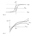
- Fig. 7 presents the characteristic waveforms associated with the invention presented in Fig. 5 as a function of the current i DC of the intermediate circuit.
- H is the strength of the magnetic field
- B x the density of the magnetic flux in the pillar
- B M is the density of the magnetic flux at the location of the permanent magnet
- B LIM is the demagnetization limit of the permanent magnet. Owing to the permanent magnet, the curves start from negative values and grow to become positive along with the external current.
- I DCN describes the measuring point of the nominal current. Since the same magnetic flux travels through both the pillar and the magnet, the density of the magnetic flux in these parts is comparable vice versa to their cross-section surfaces.
- the magnetic circuit according to the invention is dimensioned such that at the strength of the magnetic field at which the flux density of the core material in the pillar rises to the saturation limit, the flux density at the location of the permanent magnet is lower than the demagnetization limit of the material used. In this way the flux density of the permanent magnet can never grow too large, which prevents permanent changing of the properties of the DC choke in special situations.
- Fig. 8 is an example of the typical waveforms of a mains supply current when a conventional DC choke (Conventional LC) is used and when the absorption circuit according to this invention (LC+ Resonant Circuit) is in use.
- a conventional DC choke Conventional LC
- LC+ Resonant Circuit LC+ Resonant Circuit
- Fig. 9 presents some typical waveforms with a main circuit solution provided with a conventional DC choke and with a solution according to this invention.
- the figure presents the behavior of the THD (THD and THD conv), the 5th harmonic (Fifth and Fifth conv) and the ripple of the DC voltage (DC_volt PKP and DC_voltPKPconv) as a function of the output power of the frequency converter in an example case in the power range 5...40 kW (the ending -conv refers in the figure to a conventional solution).
- the solution according to the invention both the total THD and the 5th harmonic significantly decrease compared to a conventional LC circuit solution, e.g. at a nominal 40kW output power THD 42% vs.
Landscapes
- Engineering & Computer Science (AREA)
- Power Engineering (AREA)
- Rectifiers (AREA)
- Power Conversion In General (AREA)
Applications Claiming Priority (1)
| Application Number | Priority Date | Filing Date | Title |
|---|---|---|---|
| FI20070212A FI121643B (fi) | 2007-03-16 | 2007-03-16 | Virran yliaaltojen rajoitus |
Publications (2)
| Publication Number | Publication Date |
|---|---|
| EP1971016A2 true EP1971016A2 (fr) | 2008-09-17 |
| EP1971016A3 EP1971016A3 (fr) | 2009-07-15 |
Family
ID=37930016
Family Applications (1)
| Application Number | Title | Priority Date | Filing Date |
|---|---|---|---|
| EP08075183A Withdrawn EP1971016A3 (fr) | 2007-03-16 | 2008-03-12 | Circuit de suppression des harmoniques de courant |
Country Status (3)
| Country | Link |
|---|---|
| US (1) | US7593244B2 (fr) |
| EP (1) | EP1971016A3 (fr) |
| FI (1) | FI121643B (fr) |
Cited By (6)
| Publication number | Priority date | Publication date | Assignee | Title |
|---|---|---|---|---|
| WO2010086788A2 (fr) | 2009-01-29 | 2010-08-05 | Brusa Elektronik Ag | Convertisseur destiné à une utilisation monophasée et triphasée, alimentation en tension continue et chargeur de pile |
| CN101951165A (zh) * | 2010-09-16 | 2011-01-19 | 上海交通大学 | 直流链路的单相交流变换器 |
| WO2013132131A1 (fr) * | 2012-03-08 | 2013-09-12 | Torytrans, S.L. | Dispositif inducteur autocouplé à noyau unique |
| US8866332B2 (en) | 2009-06-24 | 2014-10-21 | Brusa Elektronik Ag | Circuit arrangement for power distribution in a motor vehicle |
| WO2019048186A1 (fr) * | 2017-09-05 | 2019-03-14 | Siemens Mobility GmbH | Dispositif convertisseur |
| EP3952085A1 (fr) * | 2020-08-04 | 2022-02-09 | Siemens Aktiengesellschaft | Convertisseur de puissance avec filtre de mode commun |
Families Citing this family (9)
| Publication number | Priority date | Publication date | Assignee | Title |
|---|---|---|---|---|
| US8514601B2 (en) * | 2009-08-17 | 2013-08-20 | Ideal Power Converters, Inc. | Power conversion with added pseudo-phase |
| US8125304B2 (en) * | 2008-09-30 | 2012-02-28 | Rockwell Automation Technologies, Inc. | Power electronic module with an improved choke and methods of making same |
| US8179701B2 (en) * | 2009-01-09 | 2012-05-15 | Yaskawa America, Inc. | Variable frequency drive soft charge circuit |
| DE102009017023A1 (de) * | 2009-04-14 | 2010-10-28 | Siemens Aktiengesellschaft | Antriebssystem für eine Anlage mit einem Wechselspannungsinselnetz |
| AT12748U1 (de) * | 2009-09-08 | 2012-10-15 | Siemens Ag | Frequenzumrichteranordnung |
| WO2012001627A2 (fr) | 2010-06-29 | 2012-01-05 | Brusa Elektronik Ag | Convertisseur de tension |
| US8605469B2 (en) | 2012-02-13 | 2013-12-10 | Yasakawa America, Inc. | AC side soft charge circuit for variable frequency drives |
| KR101386830B1 (ko) * | 2012-05-29 | 2014-04-29 | 엘에스산전 주식회사 | 역률보상회로 |
| DE102019118927A1 (de) * | 2019-07-12 | 2021-01-14 | Vacon Oy | Gleichstromzwischenkreisladeanordnung und Verfahren zum Laden eines Gleichstromzwischenkreiskondensators |
Citations (1)
| Publication number | Priority date | Publication date | Assignee | Title |
|---|---|---|---|---|
| US6753751B2 (en) | 2000-11-30 | 2004-06-22 | Nec Tokin Corporation | Magnetic core including magnet for magnetic bias and inductor component using the same |
Family Cites Families (6)
| Publication number | Priority date | Publication date | Assignee | Title |
|---|---|---|---|---|
| CH634416A5 (de) * | 1978-12-08 | 1983-01-31 | Hochspannung Forsch | Hochspannungspruefanlage zur pruefung einer isolation. |
| EP0187312B1 (fr) | 1985-01-08 | 1989-04-19 | BBC Brown Boveri AG | Circuit de filtrage |
| US5905642A (en) | 1997-11-11 | 1999-05-18 | Robicon Corporation | Apparatus and method to reduce common mode voltage from current source drives |
| DE29800567U1 (de) * | 1998-01-14 | 1998-04-09 | Siemens AG, 80333 München | Filteranordnung zur Dämpfung für Umrichter mit geregeltem Spannungszwischenkreis und sinusförmigen Phasenströmen |
| WO2000062396A1 (fr) * | 1999-04-09 | 2000-10-19 | 1061933 Ontario Inc. | Systeme attenuateur d'harmonique universel |
| JP3825678B2 (ja) * | 2001-10-30 | 2006-09-27 | 三洋電機株式会社 | 圧縮機の制御装置 |
-
2007
- 2007-03-16 FI FI20070212A patent/FI121643B/fi not_active IP Right Cessation
-
2008
- 2008-03-12 EP EP08075183A patent/EP1971016A3/fr not_active Withdrawn
- 2008-03-14 US US12/076,229 patent/US7593244B2/en not_active Expired - Fee Related
Patent Citations (1)
| Publication number | Priority date | Publication date | Assignee | Title |
|---|---|---|---|---|
| US6753751B2 (en) | 2000-11-30 | 2004-06-22 | Nec Tokin Corporation | Magnetic core including magnet for magnetic bias and inductor component using the same |
Cited By (12)
| Publication number | Priority date | Publication date | Assignee | Title |
|---|---|---|---|---|
| WO2010086788A2 (fr) | 2009-01-29 | 2010-08-05 | Brusa Elektronik Ag | Convertisseur destiné à une utilisation monophasée et triphasée, alimentation en tension continue et chargeur de pile |
| WO2010086788A3 (fr) * | 2009-01-29 | 2010-10-07 | Brusa Elektronik Ag | Convertisseur destiné à une utilisation monophasée et triphasée, alimentation en tension continue et chargeur de pile |
| US8009443B2 (en) | 2009-01-29 | 2011-08-30 | Brusa Elektronik Ag | DC/DC converter and AC/DC converter |
| US8503208B2 (en) | 2009-01-29 | 2013-08-06 | Brusa Elektronik Ag | Converter for single-phase and three-phase operation, D.C. voltage supply and battery charger |
| US8866332B2 (en) | 2009-06-24 | 2014-10-21 | Brusa Elektronik Ag | Circuit arrangement for power distribution in a motor vehicle |
| CN101951165A (zh) * | 2010-09-16 | 2011-01-19 | 上海交通大学 | 直流链路的单相交流变换器 |
| WO2013132131A1 (fr) * | 2012-03-08 | 2013-09-12 | Torytrans, S.L. | Dispositif inducteur autocouplé à noyau unique |
| WO2019048186A1 (fr) * | 2017-09-05 | 2019-03-14 | Siemens Mobility GmbH | Dispositif convertisseur |
| US11228253B2 (en) | 2017-09-05 | 2022-01-18 | Siemens Mobility GmbH | Converter arrangement with reduced influence of interference frequencies |
| EP3952085A1 (fr) * | 2020-08-04 | 2022-02-09 | Siemens Aktiengesellschaft | Convertisseur de puissance avec filtre de mode commun |
| WO2022028754A1 (fr) * | 2020-08-04 | 2022-02-10 | Siemens Aktiengesellschaft | Convertisseur de puissance avec filtre de mode commun |
| US12255526B2 (en) | 2020-08-04 | 2025-03-18 | Siemens Aktiengesellschaft | Power converter with common mode filter |
Also Published As
| Publication number | Publication date |
|---|---|
| EP1971016A3 (fr) | 2009-07-15 |
| US7593244B2 (en) | 2009-09-22 |
| FI121643B (fi) | 2011-02-15 |
| FI20070212A0 (fi) | 2007-03-16 |
| US20080259658A1 (en) | 2008-10-23 |
| FI20070212L (fi) | 2008-09-17 |
Similar Documents
| Publication | Publication Date | Title |
|---|---|---|
| US7593244B2 (en) | Limit for the harmonics of a current | |
| US10186974B2 (en) | Magnetic integrated device for coupling with a three-phase parallel circuit and power conversion circuit | |
| US11418106B2 (en) | Apparatus for conversion between AC power and DC power | |
| US8890642B2 (en) | Integrated magnetic device for low harmonics three-phase front-end | |
| US7847663B2 (en) | Filtering choke arrangement | |
| US20150180350A1 (en) | Resonant bidirectional converter, uninterruptible power supply apparatus, and control method | |
| US8179066B2 (en) | Method for controlling a load with a predominantly inductive character and a device applying such a method | |
| US20090140829A1 (en) | Filtering choke arrangement | |
| US20200286670A1 (en) | Transformers Having Integrated Magnetic Structures For Power Converters | |
| EP1579555A2 (fr) | Circuit de redressement a faible harmonique | |
| US11114932B1 (en) | Method and apparatus for reduction of ripple current | |
| CN101572163A (zh) | 电抗器设备 | |
| RU2051468C1 (ru) | Преобразователь переменного тока в постоянный | |
| Chiba et al. | Current balancing and phase shedding by split capacitor for a three-phase LLC resonant converter | |
| KR20090128260A (ko) | 집적화된 트랜스포머를 이용한 전원 장치 | |
| CN222720185U (zh) | 基于磁流变材料的智能可变电感器和llc谐振变换器 | |
| US12494314B2 (en) | Common mode choke for connecting to DC side of power converter, filter arrangement, and power converter | |
| WO2020115360A1 (fr) | Conception d'onduleur comprenant un inducteur non linéaire | |
| CN110610795A (zh) | 一种用于二相整流器的三相变压器 | |
| CN214177157U (zh) | 一种单级滤波器 | |
| Endo et al. | Experimental study of interleaved Y-Inverter performance | |
| US5886507A (en) | Controlled ferroresonant transformer | |
| JP2000306744A (ja) | 電源トランス | |
| JP2000164436A (ja) | 高周波パワートランスおよびこれを用いた電力変換装置 | |
| CN117457347A (zh) | 一种磁控变压器 |
Legal Events
| Date | Code | Title | Description |
|---|---|---|---|
| PUAI | Public reference made under article 153(3) epc to a published international application that has entered the european phase |
Free format text: ORIGINAL CODE: 0009012 |
|
| AK | Designated contracting states |
Kind code of ref document: A2 Designated state(s): AT BE BG CH CY CZ DE DK EE ES FI FR GB GR HR HU IE IS IT LI LT LU LV MC MT NL NO PL PT RO SE SI SK TR |
|
| AX | Request for extension of the european patent |
Extension state: AL BA MK RS |
|
| PUAL | Search report despatched |
Free format text: ORIGINAL CODE: 0009013 |
|
| RIC1 | Information provided on ipc code assigned before grant |
Ipc: H02M 1/42 20070101ALI20090528BHEP Ipc: H02M 1/12 20060101AFI20080623BHEP |
|
| AK | Designated contracting states |
Kind code of ref document: A3 Designated state(s): AT BE BG CH CY CZ DE DK EE ES FI FR GB GR HR HU IE IS IT LI LT LU LV MC MT NL NO PL PT RO SE SI SK TR |
|
| AX | Request for extension of the european patent |
Extension state: AL BA MK RS |
|
| 17P | Request for examination filed |
Effective date: 20090813 |
|
| 17Q | First examination report despatched |
Effective date: 20090909 |
|
| AKX | Designation fees paid |
Designated state(s): AT BE BG CH CY CZ DE DK EE ES FI FR GB GR HR HU IE IS IT LI LT LU LV MC MT NL NO PL PT RO SE SI SK TR |
|
| RAP1 | Party data changed (applicant data changed or rights of an application transferred) |
Owner name: VACON OY |
|
| GRAP | Despatch of communication of intention to grant a patent |
Free format text: ORIGINAL CODE: EPIDOSNIGR1 |
|
| INTG | Intention to grant announced |
Effective date: 20161019 |
|
| STAA | Information on the status of an ep patent application or granted ep patent |
Free format text: STATUS: THE APPLICATION IS DEEMED TO BE WITHDRAWN |
|
| 18D | Application deemed to be withdrawn |
Effective date: 20170301 |