EP1971121A2 - Appareil pour scanner un document double face et procédé pour scanner un document double face en utilisant cet appareil - Google Patents
Appareil pour scanner un document double face et procédé pour scanner un document double face en utilisant cet appareil Download PDFInfo
- Publication number
- EP1971121A2 EP1971121A2 EP20070123226 EP07123226A EP1971121A2 EP 1971121 A2 EP1971121 A2 EP 1971121A2 EP 20070123226 EP20070123226 EP 20070123226 EP 07123226 A EP07123226 A EP 07123226A EP 1971121 A2 EP1971121 A2 EP 1971121A2
- Authority
- EP
- European Patent Office
- Prior art keywords
- sheet
- reverse
- rollers
- scan
- document
- Prior art date
- Legal status (The legal status is an assumption and is not a legal conclusion. Google has not performed a legal analysis and makes no representation as to the accuracy of the status listed.)
- Granted
Links
Images






Classifications
-
- H—ELECTRICITY
- H04—ELECTRIC COMMUNICATION TECHNIQUE
- H04N—PICTORIAL COMMUNICATION, e.g. TELEVISION
- H04N1/00—Scanning, transmission or reproduction of documents or the like, e.g. facsimile transmission; Details thereof
- H04N1/00567—Handling of original or reproduction media, e.g. cutting, separating, stacking
- H04N1/0057—Conveying sheets before or after scanning
-
- G—PHYSICS
- G06—COMPUTING OR CALCULATING; COUNTING
- G06V—IMAGE OR VIDEO RECOGNITION OR UNDERSTANDING
- G06V10/00—Arrangements for image or video recognition or understanding
- G06V10/10—Image acquisition
-
- G—PHYSICS
- G06—COMPUTING OR CALCULATING; COUNTING
- G06K—GRAPHICAL DATA READING; PRESENTATION OF DATA; RECORD CARRIERS; HANDLING RECORD CARRIERS
- G06K7/00—Methods or arrangements for sensing record carriers, e.g. for reading patterns
-
- H—ELECTRICITY
- H04—ELECTRIC COMMUNICATION TECHNIQUE
- H04N—PICTORIAL COMMUNICATION, e.g. TELEVISION
- H04N1/00—Scanning, transmission or reproduction of documents or the like, e.g. facsimile transmission; Details thereof
- H04N1/00567—Handling of original or reproduction media, e.g. cutting, separating, stacking
- H04N1/0057—Conveying sheets before or after scanning
- H04N1/00572—Conveying sheets before or after scanning with refeeding for double-sided scanning, e.g. using one scanning head for both sides of a sheet
- H04N1/00575—Inverting the sheet prior to refeeding
- H04N1/00578—Inverting the sheet prior to refeeding using at least part of a loop, e.g. using a return loop
-
- H—ELECTRICITY
- H04—ELECTRIC COMMUNICATION TECHNIQUE
- H04N—PICTORIAL COMMUNICATION, e.g. TELEVISION
- H04N1/00—Scanning, transmission or reproduction of documents or the like, e.g. facsimile transmission; Details thereof
- H04N1/00567—Handling of original or reproduction media, e.g. cutting, separating, stacking
- H04N1/0057—Conveying sheets before or after scanning
- H04N1/00572—Conveying sheets before or after scanning with refeeding for double-sided scanning, e.g. using one scanning head for both sides of a sheet
- H04N1/00575—Inverting the sheet prior to refeeding
- H04N1/0058—Inverting the sheet prior to refeeding using at least one dead-end path, e.g. using a sheet ejection path
-
- H—ELECTRICITY
- H04—ELECTRIC COMMUNICATION TECHNIQUE
- H04N—PICTORIAL COMMUNICATION, e.g. TELEVISION
- H04N1/00—Scanning, transmission or reproduction of documents or the like, e.g. facsimile transmission; Details thereof
- H04N1/00567—Handling of original or reproduction media, e.g. cutting, separating, stacking
- H04N1/0057—Conveying sheets before or after scanning
- H04N1/00599—Using specific components
- H04N1/00602—Feed rollers
-
- H—ELECTRICITY
- H04—ELECTRIC COMMUNICATION TECHNIQUE
- H04N—PICTORIAL COMMUNICATION, e.g. TELEVISION
- H04N1/00—Scanning, transmission or reproduction of documents or the like, e.g. facsimile transmission; Details thereof
- H04N1/00567—Handling of original or reproduction media, e.g. cutting, separating, stacking
- H04N1/0057—Conveying sheets before or after scanning
- H04N1/00599—Using specific components
- H04N1/00612—Path switches
-
- H—ELECTRICITY
- H04—ELECTRIC COMMUNICATION TECHNIQUE
- H04N—PICTORIAL COMMUNICATION, e.g. TELEVISION
- H04N1/00—Scanning, transmission or reproduction of documents or the like, e.g. facsimile transmission; Details thereof
- H04N1/00567—Handling of original or reproduction media, e.g. cutting, separating, stacking
- H04N1/00641—Sorting, reordering or inverting
Definitions
- aspects of the present invention relate to duplex document scanning methods and apparatus for sequentially reading images from both sides of a document.
- duplex document scanning apparatuses In conventional duplex document scanning apparatuses, a duplex document is automatically fed and images are read from both sides of the duplex document.
- Such conventional duplex document scanning apparatuses are widely used for various image reading/processing devices such as scanners, copiers, fax machines, and multifunctional apparatuses.
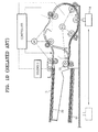
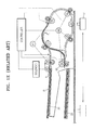
- FIGS. 1A through 1E are views for illustrating an example of a conventional duplex document scanning apparatus and its scanning method disclosed in U.S. Patent No. 5,430,536 to Fullerton et al.
- a document sheet D is picked up from a document input tray 20 and is fed along a document feed path.
- an image is read from one side of the document sheet D by a reader 14.
- the document sheet D is delivered onto a document output tray 22 by eject rollers 50. If the document sheet D is single sided (i.e., the document sheet D is a simplex sheet), the eject rollers 50 completely eject the simplex document sheet D onto the document output tray 22.
- the eject rollers 50 are reversely rotated before the duplex document sheet D is fully ejected so that the other side of the duplex document sheet D may be read by the reader 14 as shown in FIG. 1C .
- a back edge of the duplex document sheet D passes by the reader 14 first.
- the duplex document sheet D can be fed again along the document feed path so that an image from the other side of the duplex document sheet D may be read.
- the duplex document sheets D may be stacked on the document output tray 22 in a reverse order when compared to the order in which the duplex document sheets D were initially stacked on the document input tray 20.
- the simplex document sheets D are stacked on the document input tray 20 with front sides of the simplex document sheets D facing up.
- the simplex document sheets D are sequentially stacked on the document output tray 22 with the front sides of the simplex document sheets D facing down.
- the simplex document sheets D are stacked in the same initial order as that of when the simplex document sheets D were initially stacked on the document input tray 20 but the simplex document sheets D are upside-down.
- the duplex document sheets D are stacked on the document output tray 22 with the front sides of the duplex document sheets D facing up since the duplex document sheets D pass by the reader 14 two times as described above.
- the stacked order of the duplex document sheets D is reversed after scanning both of the sides, and thus, it is very inconvenient to rearrange the duplex document sheets D in the order in which the duplex document sheets D were initially stacked on the document input tray 20.
- each duplex document sheet D is fed along the document feed passage one more time as shown in FIG. 1E .
- the duplex document sheet D is fed back by the reverse rotation of the eject rollers 50 back into the document feed path across the reader 14 one more time to reverse the duplex document sheet D, and then, the duplex document sheet D is ejected onto the document output tray 22.
- the duplex document sheets D are stacked on the document output tray 22 in the same initial stack order that the duplex document sheets D were stacked on the document input tray 20.
- duplex document sheets D have been scanned in this way, it takes substantial time to scan and stack the duplex document sheets D in the correct order as each of the duplex document sheets D must pass by the reader 14 three times.
- the next duplex document sheet D can be fed, which increases the time required for scanning the duplex document sheets D.
- the increase of scanning time is negligible when one or two duplex document sheets D are scanned, the increase in scanning time cannot be neglected when tens to several hundreds of duplex document sheets D need scanning.
- an apparatus for scanning a duplex document comprising: a scan unit including a reader which sequentially scans both sides of a sheet of a duplex document by moving the sheet across the reader; and a reverse output unit to receive the sheet from the scan unit after both sides of the sheet have been scanned and to output the sheet after turning over the sheet.
- the reverse output unit may operate separately from the scan unit.
- the scan unit may include: a document input unit to feed the sheet of the duplex document; and a scan side changer to temporarily store the sheet after a first side of the sheet has been scanned by the reader and guiding the sheet back to pass by the reader so that a second side of the sheet faces the reader.
- the scan side changer may include: a scan side changer tray to temporarily support the sheet after the first side of the sheet has been scanned by the reader; and scan side changer rollers to rotate in a forward direction to feed the sheet to the scan side changer tray after the first side of the sheet has been scanned and to rotate in a reverse direction to feed the sheet back to pass the reader.
- the reverse output unit may comprise: a reverse output tray to temporarily support the sheet after both sides of the sheet have been scanned; a final output tray onto which the sheet is discharged from the reverse output tray; stack side reverse rollers to rotate in a forward direction to move the sheet onto the reverse output tray after both sides of the sheet have been scanned and to rotate in a reverse direction to move the sheet from the reverse output tray to the final output tray; and final output rollers to receive the sheet from the stack side reverse rollers when the stack side reverse rollers rotate in the reverse direction, and to transfer the sheet onto the final output tray. Further, the sheet is turned over between the reverse output tray and the final output tray.
- the scan side changer rollers, the stack side reverse rollers, and the final output rollers may be driven by a single motor.
- the scan side changer roller among the three rollers may be driven by other motors.
- the apparatus may satisfy the following condition: L1+L2 ⁇ L3+M in which L3 represents a path length between a read point P1 of the reader and a reverse point P2 of the scan side changer rollers, L1 represents a path length between the read point P1 of the reader and a reverse point P3 of the stack side reverse rollers, L1 represents a path length between the reverse point P3 of the stack side reverse rollers and a center of the nip of the final output rollers, and M represents a preset value of an allowable distance between two sheets that sequentially pass the reader.
- the first path may guide the sheet to a final output tray of the reverse output unit without turning over the sheet after the first side of the sheet has been scanned when only the first side of the sheet is to be scanned
- the second path guides the sheet to a scan side changer of the scan unit in order to scan the second side of the sheet after the first side of the sheet has been scanned when both sides of the sheet are to be scanned
- the third path guides the sheet to a reverse output tray of the reverse output unit in order to turn over the sheet after both sides of the sheet have been scanned.
- a method of scanning a duplex document comprising: while feeding a sheet of a duplex document into a scan unit and turning over the sheet, sequentially scanning both sides of the sheet using a reader included in the scan unit; and after both sides of the sheet have been scanned, turning over the sheet by feeding the sheet to a reverse output unit operates separately from the scan unit so as to output the sheet of the duplex document in the same initial order that the sheet of the duplex document was originally stacked.
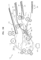
- FIG. 2A through 2I are cross-sectional views for explaining a duplex scanning method using a duplex document scanning apparatus, according to an embodiment of the present invention.
- a duplex scanning apparatus and a duplex scanning method aspects of the current invention do not limit this disclosure to only scanning of duplex documents. Specifically, aspects of the current invention provide for the scanning of simplex documents as hereinafter described.
- the duplex document scanning apparatus includes a scan unit 100 and a reverse output unit 200 that are adjacent but disposed in different locations.
- the scan unit 100 sequentially scans both sides of a duplex document sheet.
- the reverse output unit 200 turns the duplex document sheet over after both sides of the duplex document sheet have been scanned so as to output the duplex document sheet in the same order as the order in which the sheets of the duplex document were stacked on the document tray 111.
- the reverse output unit 200 turns over the sheet via a path separate from the document feed path of the scan unit 100.
- a duplex document sheet must not be fed to the document feed path until after the previous duplex document sheet is reversed using the document feed path so as to correct the stack order .
- the scan unit 100, for duplex scanning, and the reverse output unit 200, for reversing the stack order are disposed in different locations such that a duplex document sheet can be fed more rapidly after the previous duplex document sheet has been fed.
- a path selection member 140 is disposed in front of the reverse output unit 200 to guide the document sheets to a path that differs according to a switching position of the path selection member 140 as described later in more detail.
- the scan unit 100 may include a document input unit 110, a reader 120, and a scan side changer 130.
- the document input unit 110 feeds a first sheet D1 of a document into the duplex document scanning apparatus, and the reader 120 scans both sides of the first sheet D1.
- the scan side changer 130 receives the first sheet D1 after one side of the first sheet D1 has been scanned by the reader 120. Then, the scan side changer 130 feeds the first sheet D1 back to pass by the reader 120 in a manner such that the other side of the first sheet D1 faces the reader 120 and is scanned.
- the first sheet D1 is fed from a document input tray 111 of the document input unit 110 into the duplex document scanning apparatus by pick-up rollers 112 and a feed roller 113.
- alignment rollers 114 align a first edge of the first sheet D1, and then one side of the first sheet D1 is scanned while the first sheet D1 passes by the reader 120 as shown in FIG. 2A .
- the path selection member 140 may guide the first sheet D1 along a first path 140a as shown in FIG. 2B .
- the first sheet D1 is a single-sided or simplex sheet
- the first sheet D1 is guided from the reader 120 directly onto a final output tray 222 of the reverse output unit 200 along the first path 140a.
- sheets of the simplex document can be fed at predetermined time intervals in a manner such that a sheet of the simplex document can be fed while the previous sheet of the simplex document is scanned.
- the first sheet D1 is a duplex sheet
- the first sheet D1 is guided to the scan side changer 130 along a second path 140b by the path selection member 140 after one side of the first sheet D1 has been scanned by the reader 120 as shown in FIG. 2C .
- the first sheet D1 is temporarily discharged to a scan side changer tray 132 by scan side changer rollers 131 of the scan side changer 130.
- the first sheet D1 is guided back to pass by the reader 120 when the scan side changer rollers 131 rotate in a reverse direction.
- a second edge of the first sheet D1 reaches the reader 120 first with the other side of the first sheet D1 facing the reader 120 as shown in FIG. 2E .
- the duplex document scanning apparatus includes a path switch lever 141.
- the path switch lever 141 When the first sheet D1 is received by the scan side changer 130 after one side of the first sheet D1 has been scanned, the path switch lever 141 is rotated counter-clockwise by a first edge of the first sheet D1 as shown in FIG. 2C as the first sheet D1 passes between the path switch lever 141 and the path selection member 140 to be temporarily supported on the scan side changer tray 132. After the first sheet D1 has passed by the path switch lever 141, the path switch lever 141 rotates clockwise due to gravity to its original position as shown in FIG. 2D .
- the path switch lever 141 is not limited thereto.
- the path switch lever 141 may rotate and guide the document sheets mechanically or otherwise. Further, the path switch lever 141 may operate to indicate a location of the first and second sheets D1 and D2.
- First edge and second edge are used herein to describe the edges of the document sheets with respect to the initial motion of the document sheets such that the first edge is the first edge to cross a specific point along the document feed path in the first pass across the reader 120.
- the first edge of the first sheet D1 pushes against the path switch lever 141 after having been guided through the second path 140b by the path selection member 140 to be partially ejected to the scan side changer tray 132 by scan side changer rollers 131 of the scan side changer 130.
- the scan side changer rollers 131 release the second edge of the first sheet D1 reverse direction to feed the first sheet D1 back to the reader 120.
- the second edge of the first sheet D1 is now guided by the path switch lever 141 back to the document feed path so that the other side of the first sheet D1 is scanned by the reader 120 as shown in FIG. 2E .
- the second edge of the first sheet D1 is then guided through the third path 140c by the path selection member 140 to the reverse output unit 200.
- the first sheet D1 is then partially ejected to the reverse output tray 212, and the stack reverse rollers 211 reverse direction before releasing the first edge of the first sheet D1 as shown in FIG. 2F .
- the first edge of the first sheet D1 is then guided by the path switch lever 142 to the final output rollers 221 to completely eject the first sheet D1 to stack the sheet D1 on the final output tray 222 in the proper order as shown in FIGs. 2G and 2H .
- the first sheet D1 is discharged from the scan unit 100 to the reverse output unit 200 along a third path 140c of the path selection member 140. Thereafter, the first sheet D1 is turned over by the reverse output unit 200 so that the first sheet D1 can be stacked on the reverse output unit 200 in the same order as the order in which the first sheet D1 was stacked on the document input unit 110. Since the first sheet D1 is reversed by the reverse output unit 200, which does not use the document feed path, one side of the next or second sheet D2 can be scanned without any interference by the reversing motion of the previous first sheet D1. Therefore, referring to FIG.
- the next second sheet D2 can be fed into the scan unit 100 for the front or first side of the second sheet D2 to be scanned.
- the next second sheet D2 can pass by the reader 120 with its first edge at a predetermined distance from an edge of the first sheet D1. For example, as the first sheet D1 has passes the reader 120 traveling with the second edge first, the first edge of the second sheet D2 can pass the reader 120 to scan the first side of the second sheet D2 at a distance of about 90 to 140 mm behind the first edge of the first sheet D1 as the first sheet D1 travels having the second edge first.
- the first sheet D1 is temporarily discharged or partially ejected to a reverse output tray 212 after the back or other side of the first sheet D1 has been scanned and is guided to the final output tray 222 through final output rollers 221 by a reverse rotation of stack side reverse rollers 211 as shown in FIG. 2G .
- a path switch lever 142 guides the first sheet D1 to the final output tray 222.
- the path switch lever 142 may operate to indicate a location of the first sheet D1.
- the second sheet D2 is temporarily discharged or partially ejected to the scan side changer tray 132 by the scan side changer rollers 131 as shown in FIG. 2G .
- the second sheet D2 is guided back to pass by the reader 120 by a reverse rotation of the scan side changer rollers 131 as shown in FIGS. 2H and 2I , so that the back or other side of the second sheet D2 can be scanned, and thus, both sides of remaining sheets of the document can be scanned by repeating the above-described operations.
- a duplex document sheet is fed after the previous duplex document sheet has finally reversed.
- the duplex document scanning apparatus includes sensors S used to detect the location of a document sheet along the paths so that each roller may be rotated at a desired time.
- the pick-up rollers 112 pick up the first sheet D1 from the document input tray 111.
- the first sheet D1 passes by the feed roller 113, and then, the alignment rollers 114 align the first edge of the first sheet D1.
- the first sheet D1 passes by the reader 120, and one side of the first sheet D1 is scanned as shown in FIG. 2C .
- the first sheet D1 is temporarily discharged or partially ejected to the scan side changer tray 132 of the scan side changer 130 as shown in FIG. 2D .
- the first sheet D1 is fed back to pass by the reader 120 by a reverse rotation of the scan side changer rollers 131, and the reader 120 scans the other side of the first sheet D1 as shown in FIG. 2E . While the other side of the first sheet D1 is scanned, the next or second sheet D2 is fed at a predetermined distance away from the first sheet D1. As a result, referring to FIG. 2F , while the first sheet D1 is discharged to the reverse output unit 200, one side of the second sheet D2 can be scanned. In the reverse output unit 200, the first sheet D1 is temporarily discharged or partially ejected to the reverse output tray 212 and then is finally discharged to the final output tray 222 by a reverse rotation of the stack side reverse rollers 211.
- the second sheet D2 is guided to the scan side changer 130 as shown in FIGs. 2G through 2I . Thereafter, the second sheet D2 is guided back to pass by the reader 120 to scan the other side of the second sheet D2. In this way, a time delay between the scanning of sheets of a duplex document can be decreased, and thus, duplex document sheets can be scanned more rapidly.
- the forward rotation of the rollers or the rollers rotating in the forward direction results in the discharge or ejection, partial or complete, of the document sheet to one of the trays.
- the reverse rotation of the rollers or the rollers rotating in the reverse direction results in the delivery of the document sheet to the scan unit 100 or the reverse output unit 200 as the case may be.
- the scan side changer rollers 131 when the scan side changer rollers 131 rotate in the forward direction, the scan side changer rollers 131 guide a document sheet to the scan side changer tray 132.
- the scan side changer rollers 131 reverse rotation to the reverse direction before the scan side changer rollers 131 completely eject or release the document sheet to the scan side changer tray.
- the scan side changer rollers 131 rotate in the reverse direction to guide the document sheet back to the scan unit 100.
- the stack side reverse rollers 211 and the final output rollers 221 of the reverse output unit 200, and the scan side changer rollers 131 of the scan side changer 130 can be driven by a single motor.
- the stack side reverse rollers 211, the final output rollers 221, and the scan side changer rollers 131 can be driven by separate motors.
- the duplex document scanning apparatus may include more components and may become bulky.
- the stack side reverse rollers 211, the final output rollers 221, and the scan side changer rollers 131 can be rotated by a single motor using gears.
- the stack side reverse rollers 211, the final output rollers 221, and the scan side changer rollers 131 are rotated in preset directions according to a rotation of a motor, sheets of a document are fed in a predetermined manner. That is, when the stack side reverse rollers 211, the final output rollers 221, and the scan side changer rollers 131 are rotated as shown in FIG. 2G , the first sheet D1 is moved to the final output tray 222 from the reverse output tray 212, and the second sheet D2 is partially ejected to the roller tray 132.
- the stack side reverse rollers 211, the final output rollers 221, and the scan side changer rollers 131 are interconnected by gears in a manner such that the stack side reverse rollers 211, the final output rollers 221, and the scan side changer rollers 131 are rotated in preset directions by the single motor according to the movements of the first and second sheets D1 and D2.
- the stack side reverse rollers 211, the final output rollers 221, and the scan side changer rollers 131 are rotated by the single motor
- the stack side reverse rollers 211, the final output rollers 221, and the scan side changer rollers 131 are rotated simultaneously in the case where the stack side reverse rollers 211, the final output rollers 221, and the scan side changer rollers 131 are rotated in directions shown in FIG. 2G or opposite directions to those as shown in FIG. 2G .
- a first requirement for efficient duplex scanning while operating the stack side reverse rollers 211, the final output rollers 221, and the scan side changer rollers 131 with the single motor scanning is that the second sheet D2 must not reach the scan side changer rollers 131 while the first sheet D1 is being partially ejected to the stack side reverse tray 212 as the scan side changer rollers 131 are rotated in the reverse direction such that the second sheet D2 would not be guided to the scan side changer tray 132 by the scan side changer rollers 131.
- Another way to express the first requirement is that the second sheet D2 cannot reach the scan side changer rollers 131 until the stack side reverse rollers 211 and the scan side changer rollers 131 have reversed rotation directions so that when the second sheet D2 reaches the scan side changer rollers 131 the scan side changer rollers 131 are rotating in the forward direction and the stack side reverse rollers 211 are rotating in the reverse direction when the scan side changer rollers 131 and the stack side reverse rollers 211 are operated by the single motor.
- a second requirement for efficient duplex scanning while operating the stack side reverse rollers 211, the final output rollers 221, and the scan side changer rollers 131 with the single motor is that the second edge of the second sheet D2 is disposed between the scan side changer rollers 131 until the first sheet D1 is fully released from the final output rollers 221.
- the final output rollers 221 and the scan side changer rollers 131 continue to rotate in the forward rotation at least until the first sheet D1 is fully ejected to the final output tray 222 while the scan side changer rollers maintain contact with the second sheet D2 so that the second sheet D2 is only partially ejected to the scan side changer tray 132 when the final output rollers 221 and the scan side changer rollers 131 are operated by a single motor.
- FIG. 3 is a cross-sectional view to illustrate a method of reducing the number of motors in the duplex document scanning apparatus depicted in FIGs. 2A through 2I .
- a length L3 is a path length between a read point P1 of the reader 120 and a reverse point P2 of the scan side changer rollers 131.
- a length L1 is a path length between the read point P1 of the reader 120 and a reverse point P3 of the stack side reverse rollers 211.
- a length L2 is a path length between the reverse point P3 of the stack side reverse rollers 211 and a center of the nip of the final output rollers 221.
- the reverse points P2 and P3 denote points where an edge of a sheet is located when the scan side changer rollers 131 and the final output rollers 221 start to rotate in a reverse direction.
- the first requirement can be satisfied such that L1 ⁇ L3+M, where M represents a preset value of an allowable distance between the first and second sheets D1 and D2 that sequentially pass the reader 120.
- M represents a preset value of an allowable distance between the first and second sheets D1 and D2 that sequentially pass the reader 120.
- the second requirement can be satisfied such that L1+L2+LD ⁇ L3+M+LD, where LD represents the length of document sheets.
- the scan side changer rollers 131 maintain contact with the second sheet D2 while the first sheet D1 is fully released from the final output rollers 221.
- the first and second requirements can be expressed by combining the above-described formulas resulting in a combined condition: L1+L2 ⁇ L3+M.
- the second requirement wholly includes the first requirement as the sum of the lengths L1+L2 is not less than the length L3+M unless the length L1 is less than the length L3+M as L1, L2, L3, and M are all positive numbers.
- the stack side reverse rollers 211, the final output rollers 221, and the scan side changer rollers 131 can be driven using a single motor according to the above-described combined condition.
- the scan side changer rollers 131 can be driven using a first motor, and the stack side reverse rollers 211 and the final output rollers 221 can be driven using a second motor.
- the first and second requirements may be not necessary, and thus, a higher degree of design freedom can be achieved.
- the scan side changer rollers 131, the stack side reverse rollers 211, and the final output rollers 221 are driven using a single motor, the number of components and the weight of the duplex document scanning apparatus can be reduced.
- the duplex document scanning apparatus and the duplex document scanning method of preferred embodiments of the invention provide the following and/or other advantages: Scanning time of a duplex document can be reduced as a sheet of the document can be fed while the second side of the previous sheet of the document is scanned. Particularly, the reduction in scanning time is very useful when a number of sheets of a duplex document need to be scanned. Also, the second side of the second sheet can be scanned while the first sheet is being turned over to result in a proper stacking order. Furthermore, since the three sets of rollers can be driven using a single motor, the duplex document scanning apparatus can be smaller and lighter.
- duplex scanning apparatus and a duplex scanning method are not limited by this disclosure to only scanning of duplex documents.
- aspects of the current invention provide for the scanning of simplex documents.
- different elements as disclosed above may be plurally provided for so as to increase efficiency in scanning.
Landscapes
- Engineering & Computer Science (AREA)
- Multimedia (AREA)
- Signal Processing (AREA)
- Physics & Mathematics (AREA)
- General Physics & Mathematics (AREA)
- Theoretical Computer Science (AREA)
- Artificial Intelligence (AREA)
- Computer Vision & Pattern Recognition (AREA)
- Facsimile Scanning Arrangements (AREA)
- Facsimiles In General (AREA)
Applications Claiming Priority (1)
| Application Number | Priority Date | Filing Date | Title |
|---|---|---|---|
| KR1020070026274A KR101080422B1 (ko) | 2007-03-16 | 2007-03-16 | 양면 원고 스캔장치 및 그것을 이용한 양면 원고 스캔방법 |
Publications (3)
| Publication Number | Publication Date |
|---|---|
| EP1971121A2 true EP1971121A2 (fr) | 2008-09-17 |
| EP1971121A3 EP1971121A3 (fr) | 2009-01-07 |
| EP1971121B1 EP1971121B1 (fr) | 2016-08-31 |
Family
ID=39513520
Family Applications (1)
| Application Number | Title | Priority Date | Filing Date |
|---|---|---|---|
| EP07123226.8A Ceased EP1971121B1 (fr) | 2007-03-16 | 2007-12-14 | Appareil pour scanner un document double face et procédé pour scanner un document double face en utilisant cet appareil |
Country Status (3)
| Country | Link |
|---|---|
| US (1) | US8200139B2 (fr) |
| EP (1) | EP1971121B1 (fr) |
| KR (1) | KR101080422B1 (fr) |
Cited By (4)
| Publication number | Priority date | Publication date | Assignee | Title |
|---|---|---|---|---|
| EP2280534A1 (fr) * | 2009-07-31 | 2011-02-02 | Sagemcom Documents Sas | Appareil de traitement de feuilles comprenant des moyens pour numériser une série de feuilles par déplacement de son organe d'acquisition numérique |
| US11796952B2 (en) | 2019-04-30 | 2023-10-24 | Hewlett-Packard Development Company, L.P. | Automatic document feeder with automated media tray extender |
| US11825048B2 (en) | 2019-08-02 | 2023-11-21 | Hewlett-Packard Development Company, L.P. | Rotatable media ramp for automatic document feeder |
| US11827480B2 (en) | 2019-07-31 | 2023-11-28 | Hewlett-Packard Development Company, L.P. | Automatic document feeder with automated media tray |
Families Citing this family (5)
| Publication number | Priority date | Publication date | Assignee | Title |
|---|---|---|---|---|
| TW201040034A (en) * | 2009-05-11 | 2010-11-16 | Asia Optical Co Inc | Double-sided paper feeding device capable of reverting to an original sequence |
| US8371500B2 (en) * | 2010-03-26 | 2013-02-12 | Xerox Corporation | Method and apparatus for sheet feeding from a media stack using a bar code scanning device in an image production device |
| US8276913B2 (en) * | 2010-05-20 | 2012-10-02 | Xerox Corporation | Letterbox media diverter |
| JP6682798B2 (ja) * | 2015-10-15 | 2020-04-15 | 富士ゼロックス株式会社 | 画像形成装置、記録材搬送装置、および画像形成システム |
| JP2024118706A (ja) * | 2023-02-21 | 2024-09-02 | セイコーエプソン株式会社 | スキャンシステム、及び、情報処理プログラム |
Citations (2)
| Publication number | Priority date | Publication date | Assignee | Title |
|---|---|---|---|---|
| EP0654933A1 (fr) | 1993-10-12 | 1995-05-24 | Xerox Corporation | Dispositif automatique de manipulation de documents simple et double face pour l'entrée électronique |
| US6101283A (en) | 1998-06-24 | 2000-08-08 | Xerox Corporation | Show-through correction for two-sided, multi-page documents |
Family Cites Families (10)
| Publication number | Priority date | Publication date | Assignee | Title |
|---|---|---|---|---|
| US4855788A (en) * | 1986-04-15 | 1989-08-08 | Sharp Kabushiki Kaisha | Copier with improved paper transporting means |
| JPS63117835A (ja) | 1986-11-06 | 1988-05-21 | Canon Inc | 画像形成装置 |
| JPH03215871A (ja) | 1990-01-19 | 1991-09-20 | Ricoh Co Ltd | 複写装置における自動両面複写制御方法 |
| JP3215871B2 (ja) | 1992-06-19 | 2001-10-09 | ティーディーケイ株式会社 | ワイヤーボンディング外観検査装置 |
| US5461468A (en) * | 1994-10-31 | 1995-10-24 | Xerox Corporation | Document handler interdocument gap control system |
| US5669056A (en) * | 1996-03-25 | 1997-09-16 | Xerox Corp | Duplex document handling system |
| JP3578068B2 (ja) * | 2000-09-04 | 2004-10-20 | 村田機械株式会社 | 両面画像読取装置及びその画像読取方法 |
| JP2005311954A (ja) | 2004-04-26 | 2005-11-04 | Sharp Corp | 原稿読取方法 |
| TWI294354B (en) * | 2006-08-18 | 2008-03-11 | Primax Electronics Ltd | Automatic sheet feeder |
| TWI357532B (en) * | 2008-02-29 | 2012-02-01 | Primax Electronics Ltd | Duplex scanning apparatus |
-
2007
- 2007-03-16 KR KR1020070026274A patent/KR101080422B1/ko not_active Expired - Fee Related
- 2007-10-11 US US11/870,630 patent/US8200139B2/en not_active Expired - Fee Related
- 2007-12-14 EP EP07123226.8A patent/EP1971121B1/fr not_active Ceased
Patent Citations (3)
| Publication number | Priority date | Publication date | Assignee | Title |
|---|---|---|---|---|
| EP0654933A1 (fr) | 1993-10-12 | 1995-05-24 | Xerox Corporation | Dispositif automatique de manipulation de documents simple et double face pour l'entrée électronique |
| US5430536A (en) | 1993-10-12 | 1995-07-04 | Xerox Corporation | Automatic duplex and simplex document handler for electronic input |
| US6101283A (en) | 1998-06-24 | 2000-08-08 | Xerox Corporation | Show-through correction for two-sided, multi-page documents |
Cited By (5)
| Publication number | Priority date | Publication date | Assignee | Title |
|---|---|---|---|---|
| EP2280534A1 (fr) * | 2009-07-31 | 2011-02-02 | Sagemcom Documents Sas | Appareil de traitement de feuilles comprenant des moyens pour numériser une série de feuilles par déplacement de son organe d'acquisition numérique |
| FR2948844A1 (fr) * | 2009-07-31 | 2011-02-04 | Sagem Comm | Appareil de traitement de feuilles comprenant des moyens pour traiter une serie de feuilles par deplacement de son organe d'acquisition numerique |
| US11796952B2 (en) | 2019-04-30 | 2023-10-24 | Hewlett-Packard Development Company, L.P. | Automatic document feeder with automated media tray extender |
| US11827480B2 (en) | 2019-07-31 | 2023-11-28 | Hewlett-Packard Development Company, L.P. | Automatic document feeder with automated media tray |
| US11825048B2 (en) | 2019-08-02 | 2023-11-21 | Hewlett-Packard Development Company, L.P. | Rotatable media ramp for automatic document feeder |
Also Published As
| Publication number | Publication date |
|---|---|
| US20080226369A1 (en) | 2008-09-18 |
| US8200139B2 (en) | 2012-06-12 |
| EP1971121B1 (fr) | 2016-08-31 |
| KR101080422B1 (ko) | 2011-11-04 |
| KR20080084474A (ko) | 2008-09-19 |
| EP1971121A3 (fr) | 2009-01-07 |
Similar Documents
| Publication | Publication Date | Title |
|---|---|---|
| EP1971121B1 (fr) | Appareil pour scanner un document double face et procédé pour scanner un document double face en utilisant cet appareil | |
| CN111573336A (zh) | 图像读取装置 | |
| JP2017114626A (ja) | シート排出装置、画像形成システムおよびシート後処理装置 | |
| JP4516894B2 (ja) | 自動原稿搬送装置およびそれを備えた画像形成装置並びに画像読取装置 | |
| US8215628B2 (en) | Folding roller control for sheet processing apparatus/method | |
| US8654364B2 (en) | Document feeding device and image forming apparatus in which even small-sized documents can be properly transported | |
| JP2017114619A (ja) | シート排出装置、画像形成システムおよびシート後処理装置 | |
| JP2004155566A (ja) | 用紙後処理装置及びこれを備える画像形成装置 | |
| JP2005187208A (ja) | シート搬送装置、シート処理装置、及び画像形成装置 | |
| JP2014152012A (ja) | 用紙後処理装置及び画像形成装置 | |
| JP3455093B2 (ja) | シート後処理装置 | |
| JP2006148294A (ja) | 原稿読取装置 | |
| JP4477652B2 (ja) | 自動原稿搬送装置、及びこれを具備した画像読取装置、並びに画像形成装置 | |
| JP3795488B2 (ja) | 画像形成装置 | |
| JP5444991B2 (ja) | 用紙処理装置、及び画像形成装置 | |
| JP2001316033A (ja) | ステープルユニット及びこれを取り付けた装置 | |
| JP2013184817A (ja) | 用紙処理装置及び画像形成システム | |
| JP2003146528A (ja) | 画像形成装置 | |
| JP7509276B2 (ja) | 画像読取装置 | |
| JP3559780B2 (ja) | シート処理装置及び画像形成装置 | |
| JP4748569B2 (ja) | トレイ装置、シート処理装置、および画像形成装置 | |
| US20250187864A1 (en) | Sheet stacking apparatus and image forming system | |
| JP4278892B2 (ja) | シートサイズ検出装置、及びこれを用いた自動原稿給紙装置 | |
| JP5874964B2 (ja) | 用紙処理装置及び画像形成装置 | |
| JP2020117392A (ja) | シート積載装置、後処理装置、画像形成装置 |
Legal Events
| Date | Code | Title | Description |
|---|---|---|---|
| PUAI | Public reference made under article 153(3) epc to a published international application that has entered the european phase |
Free format text: ORIGINAL CODE: 0009012 |
|
| AK | Designated contracting states |
Kind code of ref document: A2 Designated state(s): AT BE BG CH CY CZ DE DK EE ES FI FR GB GR HU IE IS IT LI LT LU LV MC MT NL PL PT RO SE SI SK TR |
|
| AX | Request for extension of the european patent |
Extension state: AL BA HR MK RS |
|
| PUAL | Search report despatched |
Free format text: ORIGINAL CODE: 0009013 |
|
| AK | Designated contracting states |
Kind code of ref document: A3 Designated state(s): AT BE BG CH CY CZ DE DK EE ES FI FR GB GR HU IE IS IT LI LT LU LV MC MT NL PL PT RO SE SI SK TR |
|
| AX | Request for extension of the european patent |
Extension state: AL BA HR MK RS |
|
| 17P | Request for examination filed |
Effective date: 20090624 |
|
| AKX | Designation fees paid |
Designated state(s): DE FR GB NL |
|
| 17Q | First examination report despatched |
Effective date: 20090901 |
|
| RAP1 | Party data changed (applicant data changed or rights of an application transferred) |
Owner name: SAMSUNG ELECTRONICS CO., LTD. |
|
| GRAP | Despatch of communication of intention to grant a patent |
Free format text: ORIGINAL CODE: EPIDOSNIGR1 |
|
| GRAS | Grant fee paid |
Free format text: ORIGINAL CODE: EPIDOSNIGR3 |
|
| GRAA | (expected) grant |
Free format text: ORIGINAL CODE: 0009210 |
|
| INTG | Intention to grant announced |
Effective date: 20160706 |
|
| AK | Designated contracting states |
Kind code of ref document: B1 Designated state(s): DE FR GB NL |
|
| REG | Reference to a national code |
Ref country code: GB Ref legal event code: FG4D |
|
| REG | Reference to a national code |
Ref country code: DE Ref legal event code: R096 Ref document number: 602007047696 Country of ref document: DE |
|
| REG | Reference to a national code |
Ref country code: NL Ref legal event code: FP |
|
| REG | Reference to a national code |
Ref country code: FR Ref legal event code: PLFP Year of fee payment: 10 |
|
| REG | Reference to a national code |
Ref country code: NL Ref legal event code: PD Owner name: S-PRINTING SOLUTION CO., LTD.; KO Free format text: DETAILS ASSIGNMENT: CHANGE OF OWNER(S), ASSIGNMENT; FORMER OWNER NAME: SAMSUNG ELECTRONICS CO., LTD. Effective date: 20170221 |
|
| RAP2 | Party data changed (patent owner data changed or rights of a patent transferred) |
Owner name: S-PRINTING SOLUTION CO., LTD. |
|
| REG | Reference to a national code |
Ref country code: GB Ref legal event code: 732E Free format text: REGISTERED BETWEEN 20170406 AND 20170412 |
|
| REG | Reference to a national code |
Ref country code: DE Ref legal event code: R097 Ref document number: 602007047696 Country of ref document: DE |
|
| PLBE | No opposition filed within time limit |
Free format text: ORIGINAL CODE: 0009261 |
|
| STAA | Information on the status of an ep patent application or granted ep patent |
Free format text: STATUS: NO OPPOSITION FILED WITHIN TIME LIMIT |
|
| REG | Reference to a national code |
Ref country code: DE Ref legal event code: R082 Ref document number: 602007047696 Country of ref document: DE Representative=s name: GULDE & PARTNER PATENT- UND RECHTSANWALTSKANZL, DE Ref country code: DE Ref legal event code: R082 Ref document number: 602007047696 Country of ref document: DE Ref country code: DE Ref legal event code: R081 Ref document number: 602007047696 Country of ref document: DE Owner name: HP PRINTING KOREA CO., LTD., SUWON-SI, KR Free format text: FORMER OWNER: SAMSUNG ELECTRONICS CO., LTD., SUWON-SI, GYEONGGI-DO, KR Ref country code: DE Ref legal event code: R081 Ref document number: 602007047696 Country of ref document: DE Owner name: HEWLETT-PACKARD DEVELOPMENT COMPANY, L.P., SPR, US Free format text: FORMER OWNER: SAMSUNG ELECTRONICS CO., LTD., SUWON-SI, GYEONGGI-DO, KR Ref country code: DE Ref legal event code: R081 Ref document number: 602007047696 Country of ref document: DE Owner name: S-PRINTING SOLUTION CO., LTD., SUWON-SI, KR Free format text: FORMER OWNER: SAMSUNG ELECTRONICS CO., LTD., SUWON-SI, GYEONGGI-DO, KR |
|
| 26N | No opposition filed |
Effective date: 20170601 |
|
| REG | Reference to a national code |
Ref country code: FR Ref legal event code: TP Owner name: S-PRINTING SOLUTION CO., LTD., KR Effective date: 20170912 |
|
| REG | Reference to a national code |
Ref country code: FR Ref legal event code: PLFP Year of fee payment: 11 |
|
| REG | Reference to a national code |
Ref country code: NL Ref legal event code: HC Owner name: HP PRINTING KOREA CO., LTD.; KR Free format text: DETAILS ASSIGNMENT: CHANGE OF OWNER(S), CHANGE OF OWNER(S) NAME; FORMER OWNER NAME: S-PRINTING SOLUTION CO., LTD. Effective date: 20180816 |
|
| REG | Reference to a national code |
Ref country code: DE Ref legal event code: R082 Ref document number: 602007047696 Country of ref document: DE Ref country code: DE Ref legal event code: R081 Ref document number: 602007047696 Country of ref document: DE Owner name: HP PRINTING KOREA CO., LTD., SUWON-SI, KR Free format text: FORMER OWNER: S-PRINTING SOLUTION CO., LTD., SUWON-SI, GYEONGGI-DO, KR Ref country code: DE Ref legal event code: R081 Ref document number: 602007047696 Country of ref document: DE Owner name: HEWLETT-PACKARD DEVELOPMENT COMPANY, L.P., SPR, US Free format text: FORMER OWNER: S-PRINTING SOLUTION CO., LTD., SUWON-SI, GYEONGGI-DO, KR Ref country code: DE Ref legal event code: R082 Ref document number: 602007047696 Country of ref document: DE Representative=s name: SCHOPPE, ZIMMERMANN, STOECKELER, ZINKLER, SCHE, DE |
|
| REG | Reference to a national code |
Ref country code: NL Ref legal event code: PD Owner name: HEWLETT-PACKARD DEVELOPMENT COMPANY, L.P.; US Free format text: DETAILS ASSIGNMENT: CHANGE OF OWNER(S), CHANGE OF LEGAL ENTITY; FORMER OWNER NAME: SAMSUNG ELECTRONICS CO., LTD. Effective date: 20191030 |
|
| REG | Reference to a national code |
Ref country code: DE Ref legal event code: R081 Ref document number: 602007047696 Country of ref document: DE Owner name: HEWLETT-PACKARD DEVELOPMENT COMPANY, L.P., SPR, US Free format text: FORMER OWNER: HP PRINTING KOREA CO., LTD., SUWON-SI, GYEONGGI-DO, KR |
|
| REG | Reference to a national code |
Ref country code: GB Ref legal event code: 732E Free format text: REGISTERED BETWEEN 20191212 AND 20191218 |
|
| PGFP | Annual fee paid to national office [announced via postgrant information from national office to epo] |
Ref country code: FR Payment date: 20210608 Year of fee payment: 15 |
|
| REG | Reference to a national code |
Ref country code: DE Ref legal event code: R082 Ref document number: 602007047696 Country of ref document: DE Representative=s name: SCHOPPE, ZIMMERMANN, STOECKELER, ZINKLER, SCHE, DE |
|
| PGFP | Annual fee paid to national office [announced via postgrant information from national office to epo] |
Ref country code: NL Payment date: 20211118 Year of fee payment: 15 Ref country code: GB Payment date: 20211118 Year of fee payment: 15 Ref country code: DE Payment date: 20210528 Year of fee payment: 15 |
|
| REG | Reference to a national code |
Ref country code: DE Ref legal event code: R119 Ref document number: 602007047696 Country of ref document: DE |
|
| REG | Reference to a national code |
Ref country code: NL Ref legal event code: MM Effective date: 20230101 |
|
| GBPC | Gb: european patent ceased through non-payment of renewal fee |
Effective date: 20221214 |
|
| PG25 | Lapsed in a contracting state [announced via postgrant information from national office to epo] |
Ref country code: NL Free format text: LAPSE BECAUSE OF NON-PAYMENT OF DUE FEES Effective date: 20230101 |
|
| PG25 | Lapsed in a contracting state [announced via postgrant information from national office to epo] |
Ref country code: GB Free format text: LAPSE BECAUSE OF NON-PAYMENT OF DUE FEES Effective date: 20221214 Ref country code: DE Free format text: LAPSE BECAUSE OF NON-PAYMENT OF DUE FEES Effective date: 20230701 |
|
| PG25 | Lapsed in a contracting state [announced via postgrant information from national office to epo] |
Ref country code: FR Free format text: LAPSE BECAUSE OF NON-PAYMENT OF DUE FEES Effective date: 20221231 |