EP1972760A2 - Turbine à air humide, système de contrôle de turbine à air humide, et procédé de contrôle de turbine à air humide - Google Patents
Turbine à air humide, système de contrôle de turbine à air humide, et procédé de contrôle de turbine à air humide Download PDFInfo
- Publication number
- EP1972760A2 EP1972760A2 EP08001454A EP08001454A EP1972760A2 EP 1972760 A2 EP1972760 A2 EP 1972760A2 EP 08001454 A EP08001454 A EP 08001454A EP 08001454 A EP08001454 A EP 08001454A EP 1972760 A2 EP1972760 A2 EP 1972760A2
- Authority
- EP
- European Patent Office
- Prior art keywords
- humid air
- turbine
- humidificator
- economizer
- fuel
- Prior art date
- Legal status (The legal status is an assumption and is not a legal conclusion. Google has not performed a legal analysis and makes no representation as to the accuracy of the status listed.)
- Granted
Links
Images





Classifications
-
- F—MECHANICAL ENGINEERING; LIGHTING; HEATING; WEAPONS; BLASTING
- F02—COMBUSTION ENGINES; HOT-GAS OR COMBUSTION-PRODUCT ENGINE PLANTS
- F02C—GAS-TURBINE PLANTS; AIR INTAKES FOR JET-PROPULSION PLANTS; CONTROLLING FUEL SUPPLY IN AIR-BREATHING JET-PROPULSION PLANTS
- F02C3/00—Gas-turbine plants characterised by the use of combustion products as the working fluid
- F02C3/20—Gas-turbine plants characterised by the use of combustion products as the working fluid using a special fuel, oxidant, or dilution fluid to generate the combustion products
- F02C3/22—Gas-turbine plants characterised by the use of combustion products as the working fluid using a special fuel, oxidant, or dilution fluid to generate the combustion products the fuel or oxidant being gaseous at standard temperature and pressure
-
- F—MECHANICAL ENGINEERING; LIGHTING; HEATING; WEAPONS; BLASTING
- F01—MACHINES OR ENGINES IN GENERAL; ENGINE PLANTS IN GENERAL; STEAM ENGINES
- F01D—NON-POSITIVE DISPLACEMENT MACHINES OR ENGINES, e.g. STEAM TURBINES
- F01D25/00—Component parts, details, or accessories, not provided for in, or of interest apart from, other groups
- F01D25/30—Exhaust heads, chambers, or the like
- F01D25/305—Exhaust heads, chambers, or the like with fluid, e.g. liquid injection
-
- F—MECHANICAL ENGINEERING; LIGHTING; HEATING; WEAPONS; BLASTING
- F01—MACHINES OR ENGINES IN GENERAL; ENGINE PLANTS IN GENERAL; STEAM ENGINES
- F01D—NON-POSITIVE DISPLACEMENT MACHINES OR ENGINES, e.g. STEAM TURBINES
- F01D25/00—Component parts, details, or accessories, not provided for in, or of interest apart from, other groups
- F01D25/32—Collecting of condensation water; Drainage ; Removing solid particles
-
- F—MECHANICAL ENGINEERING; LIGHTING; HEATING; WEAPONS; BLASTING
- F02—COMBUSTION ENGINES; HOT-GAS OR COMBUSTION-PRODUCT ENGINE PLANTS
- F02C—GAS-TURBINE PLANTS; AIR INTAKES FOR JET-PROPULSION PLANTS; CONTROLLING FUEL SUPPLY IN AIR-BREATHING JET-PROPULSION PLANTS
- F02C1/00—Gas-turbine plants characterised by the use of hot gases or unheated pressurised gases, as the working fluid
- F02C1/002—Gas-turbine plants characterised by the use of hot gases or unheated pressurised gases, as the working fluid using an auxiliary fluid
- F02C1/005—Gas-turbine plants characterised by the use of hot gases or unheated pressurised gases, as the working fluid using an auxiliary fluid being recirculated
-
- F—MECHANICAL ENGINEERING; LIGHTING; HEATING; WEAPONS; BLASTING
- F02—COMBUSTION ENGINES; HOT-GAS OR COMBUSTION-PRODUCT ENGINE PLANTS
- F02C—GAS-TURBINE PLANTS; AIR INTAKES FOR JET-PROPULSION PLANTS; CONTROLLING FUEL SUPPLY IN AIR-BREATHING JET-PROPULSION PLANTS
- F02C3/00—Gas-turbine plants characterised by the use of combustion products as the working fluid
- F02C3/20—Gas-turbine plants characterised by the use of combustion products as the working fluid using a special fuel, oxidant, or dilution fluid to generate the combustion products
- F02C3/30—Adding water, steam or other fluids for influencing combustion, e.g. to obtain cleaner exhaust gases
- F02C3/305—Increasing the power, speed, torque or efficiency of a gas turbine or the thrust of a turbojet engine by injecting or adding water, steam or other fluids
-
- F—MECHANICAL ENGINEERING; LIGHTING; HEATING; WEAPONS; BLASTING
- F23—COMBUSTION APPARATUS; COMBUSTION PROCESSES
- F23L—SUPPLYING AIR OR NON-COMBUSTIBLE LIQUIDS OR GASES TO COMBUSTION APPARATUS IN GENERAL ; VALVES OR DAMPERS SPECIALLY ADAPTED FOR CONTROLLING AIR SUPPLY OR DRAUGHT IN COMBUSTION APPARATUS; INDUCING DRAUGHT IN COMBUSTION APPARATUS; TOPS FOR CHIMNEYS OR VENTILATING SHAFTS; TERMINALS FOR FLUES
- F23L2900/00—Special arrangements for supplying or treating air or oxidant for combustion; Injecting inert gas, water or steam into the combustion chamber
- F23L2900/00001—Treating oxidant before combustion, e.g. by adding a catalyst
-
- F—MECHANICAL ENGINEERING; LIGHTING; HEATING; WEAPONS; BLASTING
- F23—COMBUSTION APPARATUS; COMBUSTION PROCESSES
- F23N—REGULATING OR CONTROLLING COMBUSTION
- F23N2241/00—Applications
- F23N2241/20—Gas turbines
Definitions
- the present invention relates to a humid air turbine, humid air turbine control system, and humid air turbine control method.
- a conventional humid air turbine obtains humid air by adding water to compressed air supplied from a compressor, uses the obtained humid air to recover thermal energy possessed by exhaust discharged from the turbine, and uses the recovered thermal energy to increase its output and efficiency.
- An invention disclosed in JP-A-2005-307861 provides means for exercising control to stabilize the amount of moisture in air without regard to load variations after the start of water addition in a humid air turbine.
- thermal NOx which is generated when nitrogen in air is oxidized, accounts for the majority of NOx generated by a combustor.
- the amount of thermal NOx highly depends on temperature and increases with an increase in the temperature. Therefore, the basic idea of a low NOx combustion method is to reduce flame temperature.
- Premix combustion is known as a flame temperature reduction method that premixes fuel and air and burns the resulting mixture.
- JP-A-2003-148734 can be effectively used to deliver many small-diameter coaxial jets of fuel and air into a combustion chamber.
- the amount of moisture in combustion air in the combustor increases.
- the flame temperature lowers accordingly, thereby decreasing the amount of NOx generation.
- turbine working fluid increases in amount due to water addition, an adjustment is made to reduce the amount of fuel for the purpose of maintaining a constant turbine rotation speed.
- the flame temperature in the combustor lowers, thereby decreasing the NOx generation amount.
- the combustion air temperature lowers because the flame temperature drops to reduce the amount of heat recovered by the recuperator.
- the NOx generation amount also decreases when the flame temperature lowers.
- the present invention includes a temperature measurement device, which measures the temperature of gas discharged from the economizer, and a control device, which adjusts the amount of moisture to be supplied to the humidificator in accordance with a temperature signal from the temperature measurement device.
- the present invention makes it possible to provide a low NOx combustor and assure flame stability before and after water addition to a humid air turbine.
- Fig. 1 is a system flow diagram illustrating the overall configuration of the humid air turbine according to a first embodiment of the present invention.
- the humid air turbine 1000 includes a compressor 1 for compressing air, a combustor 2 for generating combustion gas by burning humid air and fuel, a turbine 3 driven by the combustion gas, a humidificator 4 for generating humid air by adding moisture to compressed air supplied from the compressor, and a recuperator 5 for effecting heat exchange between exhaust from the turbine and the humid air, and acquires electrical power by rotating a power generator 20 through the use of an output from the turbine 3.
- the combustor 2 is housed inside a main casing 6, a combustor casing 7, and a combustor cover 8.
- a fuel nozzle 9 is mounted at the center of the upstream end of the combustor 2.
- a combustor liner 10, which is substantially cylindrical in shape, is positioned downstream of the fuel nozzle 9 to separate unburned air from burned combustion gas.
- the outer circumference of the combustor liner 10 is provided with an external wall (hereinafter referred to as the flow sleeve 11), which forms an air flow path to exercise flow control.
- the flow sleeve 11 is larger in diameter than the combustor liner 10 and substantially concentric with the combustor liner 10.
- An inner transition duct 12 is positioned downstream of the combustor liner 10 to direct the combustion gas to the turbine 3.
- An outer transition duct 13 is positioned outside the inner transition duct 12.
- the humid air turbine according to the present embodiment also includes a water atomization cooling system 27, which sprays water 300 over turbine intake air 100 at the inlet of the compressor 1.
- the water-sprayed air 101 (atmospheric pressure) is compressed by the compressor 1 to obtain compressed air 102.
- the compressed air 102 then fills the main casing 6, flows into the space between the inner transition duct 12 and the outer transition duct 13, and convection-cools the inner transition duct 12 from its outer wall surface.
- Extraction air 103 which is obtained after the inner transition duct 12 is cooled, is extracted out of the main casing 6 through an extraction path 14, which is formed by the outer transition duct 13.
- the humid air 104 which is obtained upon water addition in the humidificator 4, is directed to the recuperator 5 and heated through heat exchange with turbine exhaust 107 (low-pressure combustion gas discharged from the turbine outlet).
- the resulting high-temperature air 105 is introduced into the combustor casing 7.
- the air in the combustor casing 7 flows toward the head of the combustor through a substantially circular space between the flow sleeve 11 and combustor liner 10, and is used to convection-cool the combustor liner 10 along the way. Part of the air flows into the combustor liner 10 through cooling air holes in the combustor liner 10 and is used for film cooling.
- the remaining air flows into the combustor liner through air holes provided downstream of the fuel nozzle 9, and turns into combustion gas 106 as it is used together with fuels (201-204) emitted from the fuel nozzle for combustion purposes.
- the high-temperature combustion gas 106 is conveyed to the turbine 3 through the inner transition duct 12.
- the low-pressure exhaust 107 discharged from the turbine 3 is heat-recovered by the recuperator 5, passed through an economizer 22, an exhaust reheater 23, and a water recovery system 24, and discharged from an exhaust tower 25 as exhaust 109. Water contained in the exhaust is recovered by the water recovery system 24 along the way.
- the water recovery method indicated in the figure sprays water onto a flue and allows the water in the gas to condense and drop for recovery purpose.
- Driving force obtained by the turbine 3 is transmitted to the compressor 1 and power generator 20 through a shaft 21. Part of the driving force is used to compress air in the compressor 1. Further, the power generator 20 converts the driving force to electrical power.
- the water recovered from the bottom of the water recovery system 24 and humidificator 4 is reused as atomization water for the water recovery system 24 or as humidification water for the humidificator 4.
- a water treatment device 26 removes impurities from the recovered water.
- the water treated by the water treatment device 26 is heated by exhaust in the economizer 22.
- the heated water is then supplied to the humidificator 4.
- Fuel flow control valves 211-214 open/close to control the amount of generated electricity MW that is output from the humid air turbine.
- the power generator 20 inputs the amount of generated electricity MW into a control device 800.
- a control valve 311 controls the amount of humidification water to be supplied to the humidificator 4.
- the control valve 311 is provided for a system that supplies water heated by the economizer 22 to the humidificator 4.
- a temperature measurement device 801 is positioned downstream of the economizer 22 to measure the exhaust temperature.
- a temperature signal acquired by the temperature measurement device 801 enters the control device 800.
- the control device 800 transmits a signal for opening/closing the control valve 311, which controls the amount of humidification water to be supplied to the humidificator 4, and signals for opening/closing the fuel flow control valves 211-214, which control the fuel flow rate.
- Fig. 1 shows a control signal for fuel flow control valve 214 as a representative of the control signals to be transmitted from the control device 800 to the fuel flow control valves 211-214.
- Fig. 2 shows the structure of the fuel nozzle 9 for use with the present embodiment.
- a fuel header 30 for the combustor cover 8 is provided with many fuel nozzles 31.
- An air hole plate 33 is provided with small-diameter air holes 32, each of which corresponds to each fuel nozzle 31, and mounted on the combustor cover 8 via a support 34.
- Coaxial jets which include a fuel jet 35 at the center and a circular air flow 36 surrounding the fuel jet, gush out of the air holes 32.
- the coaxial jets inhibit the fuel from mixing with the air within the air holes 32. This suppresses the autoignition of fuel within the air holes even when the combustion air temperature is high as in the humid air turbine. Consequently, a highly reliable combustor is obtained without melting down the air hole plate 33.
- the humid air turbine can not only reduce the amount of NOx generation, but also assure stable combustion.
- Fig. 3 is a view of the air hole plate 33 taken from the downstream side of the combustor.
- the first four rows (the first to fourth rows) from the center are classified as a first group (F1).
- the fifth row is classified as a second group (F2).
- the outer two rows (the sixth and seventh rows) are classified as a third group (F3).
- the outermost row (the eighth row) is classified as a fourth group (F4).
- fuel is supplied through flanges 41-44 provided for the fuel header 30, as shown in Fig. 2 .
- fuel staging can be performed to gradually vary the number of fuel nozzles for fuel supply in accordance with turbine load changes. This not only provides enhanced combustion stability during a partial load operation of the turbine, but also achieves NOx reduction.
- the four central rows (F1) of air holes are angled in the tangential direction of pitch circle (at ⁇ ° in Fig. 3 and at 15° in the present embodiment). These air holes are angled in this manner to whirl all the coaxial jets.
- the resulting circulating flow provides flame stability.
- flame stability is provided by the combustion heat of a central F1 burner.
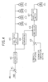
- Fig. 4 shows an example illustrating load/water addition control of the humid air turbine according to the present embodiment. It depicts a control process that is performed by the control device 800.
- a subtractor 401 determines the difference between a load demand MWD, which is transmitted from a central command center 900 ( Fig. 1 ) in accordance with a predetermined power generation amount increase rate, and an actual power generation amount MW, which is transmitted from the power generator 20.
- a controller 402 then computes a fuel flow rate command value.
- a fuel ratio setter 403 plays a role of determining the fuel flow rates for groups F1 to F4 in accordance with the fuel flow rate command value received from the controller 402.
- the fuel ratio setter 403 determines the fuel flow rates for groups F1 to F4 and the associated valve openings.
- the fuel flow control valves 211-214 are then controlled accordingly.
- a comparator 404 judges the water addition start time for water supply to the humidificator 4 in accordance with the fuel flow rate command value calculated by the controller 402. When the water addition start time arrives, the comparator 404 issues a water supply start instruction to a controller 406.
- a subtractor 405 calculates the difference between a temperature setting for the exhaust discharged from the economizer 22 and an actual temperature derived from the temperature measurement device 801.
- the temperature setting is predetermined and stored in the control device 800.
- the controller 406 determines the opening of the control valve 311 in accordance with a signal indicating the above-mentioned temperature difference.
- the value of a change rate limiter 407 is predetermined so that a water addition amount increase rate agrees with a predetermined value.
- the amount of moisture to be supplied to the humidificator is adjusted in accordance with the temperature of the gas discharged from the economizer. This makes it possible to obtain a substantially constant combustion temperature during a water addition amount increase, thereby providing a low NOx combustor and assuring flame stability
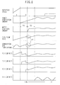
- Fig. 5 shows a combustor operating method.
- the horizontal axis of Fig. 5 indicates the elapsed time from the beginning of startup. From top to bottom, the vertical axis of Fig. 5 schematically indicates the rotation speed, the power generation amount, the water addition amount representing the amount of water supplied to the humidificator, the fuel flow rate (200), the combustion gas temperature, and F1 to F4 fuel flow rates.
- Period a is a rotation speed rise period, which is an interval between the instant at which startup is performed and the instant at which the full speed is attained.
- Period b is a load increase period for turbine startup.
- Period c is a load following operation period after the end of startup. The load increase period b is divided into the first half and the second half. The first half is a no-water-addition period b1, whereas the second half is a water addition amount increase period b2.
- fuel is supplied to a surrounding fuel system 203 so that group F3 is ignited (period b2).
- This mode of operation is referred to as the 3/4 mode.
- fuel flow control valves 211, 212, and 213 exercise fuel flow rate control so that the turbine power generation amount increases in accordance with a load increase rate predefined in a turbine startup plan.
- the fuel flow rates for the F1, F2, and F3 systems are determined in predefined proportions so as to assure combustion stability with the NOx generation amount minimized.
- the water addition to the humidificator 4 begins in the 3/4 mode.
- the control valve 311 for the humidificator opens at a predetermined rate so that the water supply flow rate gradually increases in accordance with the valve opening.
- the fuel flow rate prevailing in this instance is also controlled so that the turbine power generation amount increases in accordance with a load increase rate predefined in the turbine startup plan. Since the amount of moisture to be supplied to the humidificator 4 is adjusted in accordance with a temperature signal derived from the temperature measurement device 801, it is possible to achieve load increase and humidification while the combustion gas temperature remains substantially unchanged.
- the water supply amount 301 for the humidificator 4 or the opening of the control valve 311 reaches a predetermined value to complete the startup of the humid air turbine.
- the water supply amount prevailing after completion of startup can be controlled so that the temperature of the gas 108 discharged from the economizer agrees with a predetermined temperature.
- a load following operation is performed as the fuel flow rate increases/decreases in accordance with load increase/decrease (period c).
- a high-load operation mainly the fuel flow rate for the outermost group (F4) is adjusted as appropriate.
- F4 fuel and air mixes with the F1 to F3 combustion gases and reaches a high temperature. Therefore, fuel oxidization progresses to provide high combustion efficiency.
- air distribution is set up so that the temperature prevailing after completion of combustion is not higher than a temperature (approximately 1600°C) at which significant NOx generation occurs, combustion can be achieved in such a manner that the amount of NOx generation from group F4 is reduced to substantially zero.
- reaction is completed even when a slight amount of F4 fuel is supplied, a fuel changeover can be successively made to provide improved operability.
- Fig. 6 shows a comparison example illustrating a problem that occurs when the present invention is not used.
- the water addition amount increase rate is generally higher than a preset power generation amount increase rate. Therefore, the fuel flow rate needs to be temporarily decreased so that a predetermined power generation amount increase rate is attained at point d in Fig. 6 .
- the combustion gas temperature lowers so that combustion stability decreases.
- the size of the air holes 32 can be reduced to raise a local fuel-air ratio for the purpose of improving flame stability prevailing after water addition.
- the diameter of the air holes 32 is reduced, the combustion temperature prevailing before water addition rises due to an increase in a local fuel-air ratio, thereby increasing the NOx generation amount.
- the present invention makes it possible to reduce the amount of NOx generation before water addition and assure combustion stability after water addition. Further, since load increase and water addition during turbine startup are simultaneously accomplished, the time required for humid air turbine startup can be reduced.
- the present embodiment assumes that the temperature measurement device 801 is positioned downstream of the economizer 22. However, the temperature measurement device 801 may be positioned at an alternative place in a flow path between the combustor 2 and exhaust tower 25.
- FIG. 7 corresponds to Fig. 1 for the first embodiment.
- Fig. 8 corresponds to Fig. 5 .
- Fig. 9 corresponds to Fig. 4 .
- Fig. 7 differs from Fig. 1 in that the humidificator 4 installed in a flow path for the extraction air 103 is replaced by a water atomizer 4a. In this connection, a circulation water system for discharging water from the bottom of the humidificator 4 is also unnecessary.
- the water supply amount 301 for the humidificator 4 is larger than the amount of water that is evaporated inside the humidificator 4 and added to the humid air 104.
- the amount of evaporation in the humidificator 4 is determined by the temperature and pressure of air and water and the evaporation area of the humidificator 4. Therefore, the amount of moisture in the humid air 104 cannot be minutely adjusted.
- the water atomizer 4a used in the present embodiment operates so that the supplied water is entirely evaporated and added to air. Therefore, the amount of moisture in the humid air 104 can be minutely adjusted by controlling the water supply amount 301. Thus, control can be exercised so that the water addition amount considerably increases/decreases in accordance with an increase/decrease in the amount of power generation. Consequently, the present embodiment can shift the load following operation period C toward a small power generation amount side, as compared to the first embodiment, and enlarge the operation load range of the humid air turbine.
- the increase/decrease in the water addition amount follows the increase/decrease in the power generation amount
- the amount of combustion gas temperature increase/decrease reduces, thereby making it possible to maintain a small NOx generation amount and provide improved combustion stability.
- Fig. 9 shows an example illustrating load/water addition control of the humid air turbine according to the present embodiment. It depicts an internal system of the control device 800 ( Fig. 1 ).
- the subtractor 401 determines the difference between a load demand MWD, which is given to comply with a predetermined power generation amount increase rate, and an actual power generation amount MW.
- the controller 402 then computes a fuel flow rate command value.
- a fuel flow rate/water amount setter 408 determines the F1 to F4 fuel flow rates and the associated valve openings.
- the fuel flow control valves 211-214 are then controlled accordingly. Further, the water supply amount 301 and the associated opening of the control valve 311 are simultaneously determined. A substantially constant combustion temperature can then be maintained irrespective of an increase/decrease in the amount of water to achieve the object of the present invention.
- a subtractor 405 computes the difference between a temperature setting for the exhaust discharged from the economizer 22 and an actual temperature.
- the controller 406 determines the optimum opening of the control valve 311 in consideration of system efficiency.
- a selector 409 compares the valve opening derived from the controller 406 against the valve opening derived from the fuel flow rate/water amount setter 408 to determine either a combustion performance characteristic or system efficiency has higher priority, thereby determining the optimum water supply amount.
- the present invention is remarkably effective in reducing the NOx generation amount and assuring combustion stability.
- the humid air turbine uses a low NOx combustor that includes a plurality of premix burners positioned around a central diffusion flame burner as described in JP-A-1995-280267 or uses a combustor that includes a plurality of premix burners positioned around a central diffusion flame pilot burner as described in JP-A-2003-120934 , water addition also incurs a great conditional change in relation to the NOx generation and flame stability of the combustor. Therefore, the present invention can be effectively applied to the above-mentioned low NOx combustor.
- the present invention can be used not only as a high-efficiency turbine for power generation, but also as a cogeneration system for simultaneous generation of heat and electricity or a machine drive engine for a pump, compressor, or other machine.
Landscapes
- Engineering & Computer Science (AREA)
- Mechanical Engineering (AREA)
- General Engineering & Computer Science (AREA)
- Chemical & Material Sciences (AREA)
- Combustion & Propulsion (AREA)
- Control Of Turbines (AREA)
Applications Claiming Priority (1)
| Application Number | Priority Date | Filing Date | Title |
|---|---|---|---|
| JP2007069745A JP4466667B2 (ja) | 2007-03-19 | 2007-03-19 | 高湿分空気利用ガスタービン,高湿分空気利用ガスタービンの制御装置及び高湿分空気利用ガスタービンの制御方法 |
Publications (3)
| Publication Number | Publication Date |
|---|---|
| EP1972760A2 true EP1972760A2 (fr) | 2008-09-24 |
| EP1972760A3 EP1972760A3 (fr) | 2016-03-30 |
| EP1972760B1 EP1972760B1 (fr) | 2018-04-18 |
Family
ID=39560865
Family Applications (1)
| Application Number | Title | Priority Date | Filing Date |
|---|---|---|---|
| EP08001454.1A Active EP1972760B1 (fr) | 2007-03-19 | 2008-01-25 | Turbine à air humide, système de contrôle de turbine à air humide, et procédé de contrôle de turbine à air humide |
Country Status (3)
| Country | Link |
|---|---|
| US (1) | US8006499B2 (fr) |
| EP (1) | EP1972760B1 (fr) |
| JP (1) | JP4466667B2 (fr) |
Cited By (3)
| Publication number | Priority date | Publication date | Assignee | Title |
|---|---|---|---|---|
| CN103195587A (zh) * | 2012-01-06 | 2013-07-10 | 株式会社日立制作所 | 设置于高湿量空气利用燃气轮机的燃气轮机燃烧器的燃料控制方法及燃料控制装置 |
| EP2799669A1 (fr) * | 2013-04-30 | 2014-11-05 | Siemens Aktiengesellschaft | Procédé de charge d'une turbine à gaz |
| CN109891153A (zh) * | 2016-09-05 | 2019-06-14 | 法国德西尼布 | 减少NOx排放的方法 |
Families Citing this family (24)
| Publication number | Priority date | Publication date | Assignee | Title |
|---|---|---|---|---|
| JP4275690B2 (ja) * | 2006-09-07 | 2009-06-10 | 株式会社日立製作所 | ガスタービンシステム |
| JP4959620B2 (ja) | 2007-04-26 | 2012-06-27 | 株式会社日立製作所 | 燃焼器及び燃焼器の燃料供給方法 |
| JP4906689B2 (ja) | 2007-11-29 | 2012-03-28 | 株式会社日立製作所 | バーナ,燃焼装置及び燃焼装置の改造方法 |
| US8636836B2 (en) | 2009-02-04 | 2014-01-28 | Purdue Research Foundation | Finned heat exchangers for metal hydride storage systems |
| WO2010091178A1 (fr) | 2009-02-04 | 2010-08-12 | Purdue Research Foundation | Échangeurs de chaleur spiralés et à microcanaux pour systèmes de stockage d'hydrures métalliques |
| JP5117431B2 (ja) * | 2009-03-09 | 2013-01-16 | 株式会社日立製作所 | 二酸化炭素回収型ガスタービンプラント |
| US8763399B2 (en) * | 2009-04-03 | 2014-07-01 | Hitachi, Ltd. | Combustor having modified spacing of air blowholes in an air blowhole plate |
| JP5103454B2 (ja) * | 2009-09-30 | 2012-12-19 | 株式会社日立製作所 | 燃焼器 |
| JP5159741B2 (ja) * | 2009-09-30 | 2013-03-13 | 株式会社日立製作所 | ガスタービン燃焼器の制御装置およびガスタービン燃焼器の制御方法 |
| US20110100004A1 (en) * | 2009-10-30 | 2011-05-05 | Wael Faisal Al-Mazeedi | Adaptive control of a concentrated solar power-enabled power plant |
| JP5084847B2 (ja) * | 2010-01-13 | 2012-11-28 | 株式会社日立製作所 | ガスタービン燃焼器 |
| US8261555B2 (en) * | 2010-07-08 | 2012-09-11 | General Electric Company | Injection nozzle for a turbomachine |
| EP3141726B1 (fr) * | 2010-08-05 | 2019-10-09 | Mitsubishi Hitachi Power Systems, Ltd. | Chambre de combustion et procédé d'alimentation en carburant et buse de conversion de combustible pour turbine à air humide avancée |
| US8978386B2 (en) * | 2010-09-30 | 2015-03-17 | Mitsubishi Hitachi Power Systems, Ltd. | Gas turbine system, control device for gas turbine system, and control method for gas turbine system |
| JP5458121B2 (ja) * | 2012-01-27 | 2014-04-02 | 株式会社日立製作所 | ガスタービン燃焼器およびガスタービン燃焼器の運転方法 |
| JP5917348B2 (ja) * | 2012-09-12 | 2016-05-11 | 三菱日立パワーシステムズ株式会社 | 浄水設備の運転方法及び発電設備を併設した浄水設備 |
| US8567177B1 (en) * | 2012-11-30 | 2013-10-29 | Yoganeck, LLC | Gas turbine engine system with water recycling feature |
| JP6190670B2 (ja) * | 2013-08-30 | 2017-08-30 | 三菱日立パワーシステムズ株式会社 | ガスタービン燃焼システム |
| JP6261956B2 (ja) * | 2013-11-11 | 2018-01-17 | 三菱日立パワーシステムズ株式会社 | 高湿分利用ガスタービンシステム |
| US11384939B2 (en) * | 2014-04-21 | 2022-07-12 | Southwest Research Institute | Air-fuel micromix injector having multibank ports for adaptive cooling of high temperature combustor |
| JP6795419B2 (ja) * | 2017-02-06 | 2020-12-02 | 三菱パワー株式会社 | 湿分利用ガスタービン |
| US11466594B2 (en) | 2018-03-10 | 2022-10-11 | Gas Technology Institute | Combined cooling, heating and power system |
| CN112283708B (zh) * | 2020-11-16 | 2024-08-30 | 哈尔滨工业大学 | 一种多通道配风调节回转窑加湿低氮燃烧器 |
| CN117052538B (zh) * | 2023-08-10 | 2025-08-19 | 中国航发沈阳发动机研究所 | 一种射流预冷供水系统分区切换流量尖峰问题控制方法 |
Citations (4)
| Publication number | Priority date | Publication date | Assignee | Title |
|---|---|---|---|---|
| JPH07280267A (ja) | 1994-04-08 | 1995-10-27 | Hitachi Ltd | ガスタービン燃焼器 |
| JP2003120934A (ja) | 2001-10-15 | 2003-04-23 | Ishikawajima Harima Heavy Ind Co Ltd | ガスタービンの燃焼器 |
| JP2003148734A (ja) | 2001-08-29 | 2003-05-21 | Hitachi Ltd | ガスタービン燃焼器およびガスタービン燃焼器の運転方法 |
| JP2005307861A (ja) | 2004-04-22 | 2005-11-04 | Hitachi Ltd | 高湿分ガスタービン発電プラント,制御装置,プログラム及び記録媒体 |
Family Cites Families (24)
| Publication number | Priority date | Publication date | Assignee | Title |
|---|---|---|---|---|
| US6289666B1 (en) * | 1992-10-27 | 2001-09-18 | Ginter Vast Corporation | High efficiency low pollution hybrid Brayton cycle combustor |
| JP2877098B2 (ja) * | 1995-12-28 | 1999-03-31 | 株式会社日立製作所 | ガスタービン,コンバインドサイクルプラント及び圧縮機 |
| US6389799B1 (en) * | 1997-04-22 | 2002-05-21 | Hitachi, Ltd. | Gas turbine Installation |
| SG104914A1 (en) * | 1997-06-30 | 2004-07-30 | Hitachi Ltd | Gas turbine |
| JPH11148372A (ja) | 1997-11-17 | 1999-06-02 | Hitachi Ltd | ガスタービン |
| JPH11257096A (ja) | 1998-03-17 | 1999-09-21 | Hitachi Ltd | ガスタービン発電プラント |
| JPH11324710A (ja) * | 1998-05-20 | 1999-11-26 | Hitachi Ltd | ガスタービン発電プラント |
| JP3577539B2 (ja) | 1998-09-29 | 2004-10-13 | 株式会社日立製作所 | ガスタービン発電プラントの制御装置 |
| JP2000230432A (ja) | 1999-02-10 | 2000-08-22 | Hitachi Ltd | ガスタービン発電プラント |
| US6634165B2 (en) * | 2000-12-28 | 2003-10-21 | General Electric Company | Control system for gas turbine inlet-air water-saturation and supersaturation system |
| US6981360B2 (en) * | 2001-04-09 | 2006-01-03 | Hitachi, Ltd. | Gas turbine power generator having humidifying and cooling means |
| US6928823B2 (en) * | 2001-08-29 | 2005-08-16 | Hitachi, Ltd. | Gas turbine combustor and operating method thereof |
| US6813889B2 (en) * | 2001-08-29 | 2004-11-09 | Hitachi, Ltd. | Gas turbine combustor and operating method thereof |
| GB2382847A (en) * | 2001-12-06 | 2003-06-11 | Alstom | Gas turbine wet compression |
| US6715295B2 (en) * | 2002-05-22 | 2004-04-06 | Siemens Westinghouse Power Corporation | Gas turbine pilot burner water injection and method of operation |
| US7637093B2 (en) * | 2003-03-18 | 2009-12-29 | Fluor Technologies Corporation | Humid air turbine cycle with carbon dioxide recovery |
| JP4100316B2 (ja) * | 2003-09-30 | 2008-06-11 | 株式会社日立製作所 | ガスタービン設備 |
| JP4167989B2 (ja) | 2004-01-30 | 2008-10-22 | 株式会社日立製作所 | ガスタービン設備及びガスタービン用加湿設備 |
| JP4457778B2 (ja) * | 2004-06-30 | 2010-04-28 | 株式会社日立製作所 | 高湿分ガスタービン発電プラント |
| JP4811991B2 (ja) * | 2005-07-06 | 2011-11-09 | 株式会社日立製作所 | 高湿分利用ガスタービン設備 |
| JP4275690B2 (ja) * | 2006-09-07 | 2009-06-10 | 株式会社日立製作所 | ガスタービンシステム |
| JP4371278B2 (ja) * | 2007-08-07 | 2009-11-25 | 株式会社日立製作所 | 高湿分利用ガスタービン設備 |
| JP5143060B2 (ja) * | 2009-03-11 | 2013-02-13 | 株式会社日立製作所 | 2軸ガスタービン |
| JP5023101B2 (ja) * | 2009-04-22 | 2012-09-12 | 株式会社日立製作所 | 高湿分利用ガスタービンシステム |
-
2007
- 2007-03-19 JP JP2007069745A patent/JP4466667B2/ja active Active
-
2008
- 2008-01-23 US US12/018,574 patent/US8006499B2/en active Active
- 2008-01-25 EP EP08001454.1A patent/EP1972760B1/fr active Active
Patent Citations (4)
| Publication number | Priority date | Publication date | Assignee | Title |
|---|---|---|---|---|
| JPH07280267A (ja) | 1994-04-08 | 1995-10-27 | Hitachi Ltd | ガスタービン燃焼器 |
| JP2003148734A (ja) | 2001-08-29 | 2003-05-21 | Hitachi Ltd | ガスタービン燃焼器およびガスタービン燃焼器の運転方法 |
| JP2003120934A (ja) | 2001-10-15 | 2003-04-23 | Ishikawajima Harima Heavy Ind Co Ltd | ガスタービンの燃焼器 |
| JP2005307861A (ja) | 2004-04-22 | 2005-11-04 | Hitachi Ltd | 高湿分ガスタービン発電プラント,制御装置,プログラム及び記録媒体 |
Cited By (6)
| Publication number | Priority date | Publication date | Assignee | Title |
|---|---|---|---|---|
| CN103195587A (zh) * | 2012-01-06 | 2013-07-10 | 株式会社日立制作所 | 设置于高湿量空气利用燃气轮机的燃气轮机燃烧器的燃料控制方法及燃料控制装置 |
| CN103195587B (zh) * | 2012-01-06 | 2015-05-20 | 三菱日立电力系统株式会社 | 设置于利用高湿量空气的燃气轮机的燃气轮机燃烧器的燃料控制方法及燃料控制装置 |
| EP2613081A3 (fr) * | 2012-01-06 | 2018-01-10 | Mitsubishi Hitachi Power Systems, Ltd. | Procédé de commande d'écoulement de combustible et système de régulation d'écoulement de carburant de la chambre de combustion de turbine pour turbine à gaz de l'air humide |
| EP2799669A1 (fr) * | 2013-04-30 | 2014-11-05 | Siemens Aktiengesellschaft | Procédé de charge d'une turbine à gaz |
| CN109891153A (zh) * | 2016-09-05 | 2019-06-14 | 法国德西尼布 | 减少NOx排放的方法 |
| US11959639B2 (en) | 2016-09-05 | 2024-04-16 | Technip France | Method for reducing NOX emission |
Also Published As
| Publication number | Publication date |
|---|---|
| JP4466667B2 (ja) | 2010-05-26 |
| EP1972760B1 (fr) | 2018-04-18 |
| US8006499B2 (en) | 2011-08-30 |
| EP1972760A3 (fr) | 2016-03-30 |
| JP2008231963A (ja) | 2008-10-02 |
| US20080229755A1 (en) | 2008-09-25 |
Similar Documents
| Publication | Publication Date | Title |
|---|---|---|
| EP1972760B1 (fr) | Turbine à air humide, système de contrôle de turbine à air humide, et procédé de contrôle de turbine à air humide | |
| JP4735548B2 (ja) | 高湿分空気利用ガスタービン及びその運転方法 | |
| US9828912B2 (en) | Combined cycle power plant with flue gas recirculation | |
| EP2578942A2 (fr) | Appareil d'injection d'air direct d'extrémité de tête avec des fonctionnalités de mélange améliorées | |
| EP2491310B1 (fr) | Procédé de fonctionnement d'un système de combustion multi-combustible | |
| US9121611B2 (en) | Combustor, burner, and gas turbine | |
| US20100043387A1 (en) | Methods and systems for operating gas turbine engines | |
| JP5452634B2 (ja) | 高湿分空気利用ガスタービンに設置されるガスタービン燃焼器の燃料制御方法及び燃料制御装置 | |
| EP2500656B1 (fr) | Chambre de combustion de turbine à gaz comportant une buse d'injection pour ancrage de flamme | |
| US20040226300A1 (en) | Method of operating a flamesheet combustor | |
| EP1917469B1 (fr) | Procede utilisant un systeme de cogeneration avec un systeme auxiliaire d'air enrichi en oxygene | |
| EP2963266B1 (fr) | Centrale électrique à turbine à gaz disposant d'une turbine libre | |
| JP4409566B2 (ja) | 希薄予混合型燃焼装置とその制御方法 | |
| JP4838107B2 (ja) | ガスタービン、高湿分利用ガスタービン及びガスタービンに用いられる燃焼器 | |
| US20010022075A1 (en) | Gas turbine | |
| JP5480792B2 (ja) | ガスタービンシステム及びガスタービンの加湿制御方法 | |
| JP2006144759A (ja) | ガスタービン用予混合燃焼器およびその燃料供給制御方法 | |
| JP5183692B2 (ja) | 高湿分空気利用ガスタービン用のガスタービン燃焼器の燃料制御方法および燃料制御装置 | |
| US20170058771A1 (en) | System and method for generating steam during gas turbine low-load conditions | |
| JP5464376B2 (ja) | 燃焼器、ガスタービン及び燃焼器の燃料制御方法 | |
| US8726671B2 (en) | Operation of a combustor apparatus in a gas turbine engine | |
| CN116481024A (zh) | 一种强制回热循环自持燃烧器及自持稳燃控制方法 | |
| JP5178790B2 (ja) | 高湿分空気利用ガスタービン用のガスタービン燃焼器の燃料制御方法および燃料制御装置 | |
| JP4972533B2 (ja) | 再生型ガスタービン及び再生型ガスタービンの燃料制御方法 | |
| JP2021195876A (ja) | ガスタービンの燃焼制御方法 |
Legal Events
| Date | Code | Title | Description |
|---|---|---|---|
| PUAI | Public reference made under article 153(3) epc to a published international application that has entered the european phase |
Free format text: ORIGINAL CODE: 0009012 |
|
| 17P | Request for examination filed |
Effective date: 20080125 |
|
| AK | Designated contracting states |
Kind code of ref document: A2 Designated state(s): AT BE BG CH CY CZ DE DK EE ES FI FR GB GR HR HU IE IS IT LI LT LU LV MC MT NL NO PL PT RO SE SI SK TR |
|
| AX | Request for extension of the european patent |
Extension state: AL BA MK RS |
|
| RAP1 | Party data changed (applicant data changed or rights of an application transferred) |
Owner name: MITSUBISHI HITACHI POWER SYSTEMS, LTD. |
|
| RAP1 | Party data changed (applicant data changed or rights of an application transferred) |
Owner name: MITSUBISHI HITACHI POWER SYSTEMS, LTD. |
|
| PUAL | Search report despatched |
Free format text: ORIGINAL CODE: 0009013 |
|
| AK | Designated contracting states |
Kind code of ref document: A3 Designated state(s): AT BE BG CH CY CZ DE DK EE ES FI FR GB GR HR HU IE IS IT LI LT LU LV MC MT NL NO PL PT RO SE SI SK TR |
|
| AX | Request for extension of the european patent |
Extension state: AL BA MK RS |
|
| RIC1 | Information provided on ipc code assigned before grant |
Ipc: F01K 21/04 20060101AFI20160223BHEP Ipc: F02C 3/22 20060101ALI20160223BHEP Ipc: F02C 1/00 20060101ALI20160223BHEP Ipc: F01D 25/32 20060101ALI20160223BHEP Ipc: F02C 3/30 20060101ALI20160223BHEP Ipc: F01D 25/30 20060101ALI20160223BHEP |
|
| 17Q | First examination report despatched |
Effective date: 20160321 |
|
| STAA | Information on the status of an ep patent application or granted ep patent |
Free format text: STATUS: EXAMINATION IS IN PROGRESS |
|
| AKX | Designation fees paid |
Designated state(s): DE FR GB |
|
| AXX | Extension fees paid |
Extension state: BA Extension state: MK Extension state: RS Extension state: AL |
|
| GRAP | Despatch of communication of intention to grant a patent |
Free format text: ORIGINAL CODE: EPIDOSNIGR1 |
|
| STAA | Information on the status of an ep patent application or granted ep patent |
Free format text: STATUS: GRANT OF PATENT IS INTENDED |
|
| INTG | Intention to grant announced |
Effective date: 20171010 |
|
| GRAS | Grant fee paid |
Free format text: ORIGINAL CODE: EPIDOSNIGR3 |
|
| GRAA | (expected) grant |
Free format text: ORIGINAL CODE: 0009210 |
|
| STAA | Information on the status of an ep patent application or granted ep patent |
Free format text: STATUS: THE PATENT HAS BEEN GRANTED |
|
| RIN1 | Information on inventor provided before grant (corrected) |
Inventor name: KATAGIRI, YUKINORI Inventor name: MIURA, KEISUKE Inventor name: KOGANEZAWA, TOMOMI |
|
| AK | Designated contracting states |
Kind code of ref document: B1 Designated state(s): DE FR GB |
|
| REG | Reference to a national code |
Ref country code: GB Ref legal event code: FG4D |
|
| RIN1 | Information on inventor provided before grant (corrected) |
Inventor name: KATAGIRI, YUKINORI Inventor name: MIURA, KEISUKE Inventor name: KOGANEZAWA, TOMOMI |
|
| REG | Reference to a national code |
Ref country code: DE Ref legal event code: R096 Ref document number: 602008054853 Country of ref document: DE |
|
| REG | Reference to a national code |
Ref country code: DE Ref legal event code: R097 Ref document number: 602008054853 Country of ref document: DE |
|
| PLBE | No opposition filed within time limit |
Free format text: ORIGINAL CODE: 0009261 |
|
| STAA | Information on the status of an ep patent application or granted ep patent |
Free format text: STATUS: NO OPPOSITION FILED WITHIN TIME LIMIT |
|
| 26N | No opposition filed |
Effective date: 20190121 |
|
| REG | Reference to a national code |
Ref country code: DE Ref legal event code: R082 Ref document number: 602008054853 Country of ref document: DE Representative=s name: MERH-IP MATIAS ERNY REICHL HOFFMANN PATENTANWA, DE Ref country code: DE Ref legal event code: R081 Ref document number: 602008054853 Country of ref document: DE Owner name: MITSUBISHI POWER, LTD., JP Free format text: FORMER OWNER: MITSUBISHI HITACHI POWER SYSTEMS, LTD., YOKOHAMA, JP |
|
| PGFP | Annual fee paid to national office [announced via postgrant information from national office to epo] |
Ref country code: GB Payment date: 20251204 Year of fee payment: 19 |
|
| PGFP | Annual fee paid to national office [announced via postgrant information from national office to epo] |
Ref country code: FR Payment date: 20251128 Year of fee payment: 19 |
|
| PGFP | Annual fee paid to national office [announced via postgrant information from national office to epo] |
Ref country code: DE Payment date: 20251203 Year of fee payment: 19 |