EP1972995B1 - Appareil de projecteur, procédé de contrôle de projection et support d'enregistrement stockant le programme de contrôle de projection - Google Patents
Appareil de projecteur, procédé de contrôle de projection et support d'enregistrement stockant le programme de contrôle de projection Download PDFInfo
- Publication number
- EP1972995B1 EP1972995B1 EP08004017.3A EP08004017A EP1972995B1 EP 1972995 B1 EP1972995 B1 EP 1972995B1 EP 08004017 A EP08004017 A EP 08004017A EP 1972995 B1 EP1972995 B1 EP 1972995B1
- Authority
- EP
- European Patent Office
- Prior art keywords
- temperature
- time point
- coefficient
- optical lens
- temperature detecting
- Prior art date
- Legal status (The legal status is an assumption and is not a legal conclusion. Google has not performed a legal analysis and makes no representation as to the accuracy of the status listed.)
- Ceased
Links
Images


Classifications
-
- G—PHYSICS
- G03—PHOTOGRAPHY; CINEMATOGRAPHY; ANALOGOUS TECHNIQUES USING WAVES OTHER THAN OPTICAL WAVES; ELECTROGRAPHY; HOLOGRAPHY
- G03B—APPARATUS OR ARRANGEMENTS FOR TAKING PHOTOGRAPHS OR FOR PROJECTING OR VIEWING THEM; APPARATUS OR ARRANGEMENTS EMPLOYING ANALOGOUS TECHNIQUES USING WAVES OTHER THAN OPTICAL WAVES; ACCESSORIES THEREFOR
- G03B21/00—Projectors or projection-type viewers; Accessories therefor
- G03B21/14—Details
- G03B21/53—Means for automatic focusing, e.g. to compensate thermal effects
Definitions
- the present invention is related to a projector apparatus, a projection control method and a recording medium storing a projection control program, which are suitable for use in a projector having an automatic focus function.
- a lamp such as a high pressure mercury lamp, which reaches an extremely high temperature, is used as a light source, the rise in the lamp temperature is apt to blur the focus.
- Patent document JP 2003/161869 discloses a projector comprising a lens mounted in a lens frame and further comprising a temperature sensor 10 on the frame and a temperature sensor 12 on the lens group 2B.
- Patent document US 2006/0187532 discloses a projector which includes a sensor for measuring the temperature of the main lighting source.
- Patent document US 2005/0083491 discloses a projector apparatus comprising two temperature sensors 158 and 159 and a control unit 161.
- the projector is configured to use the control unit in order to control the position of the lens 149, by means of gear 157, based on the inputs received by the two temperature sensors so that the distance L0 between the lens and the micromirror 148 can be kept constant.
- Patent documents US 2005/0024592 discloses a digital projector and a method for automatically focusing the projector. Additionally, the document discloses the presence of a temperature sensor provided near the lamp so as to estimate the lamp brightness.
- the object of the present invention is to provide a projector apparatus, a projection control method and a recording medium storing a projection control program, which are capable of maintaining an accurate focus state at all times, by accurately revising the shift of the focus lens position caused by, for example, environmental conditions.
- a projector apparatus comprising: a light source; an optical lens unit having an automatic focus function and projecting a light figure formed by using a light emitted from the light source; a first temperature detecting unit configured to detect the temperature of the optical lens unit; a second temperature detecting unit configured to detect the temperature of a part other than the optical lens unit; and a projection control unit configured to move a position of a particular lens within the optical lens unit in accordance with the detection result of the first and second temperature detecting units, and to revise an image location set by the automatic focus function.
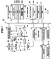
- FIG. 1 shows a configuration of an electronic circuit of a projector apparatus 10 according to the present embodiment.
- image signals of various standards which are input from an input/output connector unit 11 are sent to an image conversion unit 13 via an input/output interface (I/F) 12 and a system bus SB to be unified to an image signal of a predetermined format.
- the image signals are then sent to a projection processing unit 14.
- the projection processing unit 14 After the projection processing unit 14 develops and stores the received image signals on a video RAM 15, the projection processing unit 14 generates a video signal from the stored contents of this video RAM 15.
- the projection processing unit 14 displays, for example, a micro mirror element 16, which is a space optical modification element (SOM), by a faster time-division drive, obtained by multiplying a frame rate of the video signal, such as 60 frames per second, the division number of a color component and the number of display tones.
- SOM space optical modification element
- a light source lamp 18 which uses, for example, an ultrahigh pressure mercury lamp, and is arranged in a reflector 17 emits white light of high luminance.
- the white light emitted by the light source lamp 18 is colored to a primitive color by time division through a color wheel 19, is made into a beam of light with even luminance distribution by an integrator 20, and then is totally reflected on a mirror 21, thereby irradiating the above micro mirror element 16.
- a light figure is formed by the light reflected on the micro mirror element 16 and is projected and displayed via an optical lens unit 22 onto a screen, which is a projection target not illustrated in the drawing.
- the optical lens unit 22 is a unit which enlarges and projects the light figure formed by the micro mirror element 16 onto a target, such as a screen. It is capable of varying a focusing position and a zoom position (field angle of projection) arbitrarily.
- the focusing position is controlled by moving a focus lens 22a in the direction of an optical axis as indicated by an arrow A in the drawing.
- the focus lens 22a is moved by rotating a stepping motor (M) 23.
- a projection light processing unit 25 carries out the activation of all of lighting the above light source lamp 18, spinning a motor (M) 24 which spins the above color wheel 19, and rotating the above stepping motor 23.
- FIG. 2 exemplifies details of a temperature revision lookup table LT (291) which is stored in the above program memory 29 along with, for example, the operation program, and is read out by the control unit 28 when necessary.
- LT temperature revision lookup table
- the number of anteroposterior (+/-) steps to revise the activation position of the focus lens 22a is read out from FIG. 2 based on the difference in temperatures detected respectively by the above temperature sensors 26 and 27 as mentioned below.
- the temperature difference value is rounded off at the decimal place, and the combination of the tens figure, which is on a vertical axis, and the units figure, which is on a horizontal axis, is read out as the number of steps.
- a distance surveying processing unit 30 and a voice processing unit 31 are further connected to the control unit 28 via the system bus SB.
- the voice processing unit 31 is provided with a sound source circuit, such as a PCM sound source, which converts voice data given upon projection into analogue voice data and amplifies it on a speaker 33 by driving the speaker provided on, for example, the back of the body casing of the projector apparatus 10, or generates, for example, a beeping sound according to need.
- a sound source circuit such as a PCM sound source, which converts voice data given upon projection into analogue voice data and amplifies it on a speaker 33 by driving the speaker provided on, for example, the back of the body casing of the projector apparatus 10, or generates, for example, a beeping sound according to need.
- an operation signal is input directly from a key switch unit 34 and an IR light receiving unit 35 in accordance with the key operation of a user.
- the key switch unit 34 comprises, for example, a power supply key, an AFK (Auto Focus / auto Key-stone correction) key, a zoom key, an input selection key, a cursor (" ⁇ ", " ⁇ ", “ ⁇ ”, “ ⁇ ") key, and "Enter” key, and a "Cancel” key.
- AFK Automatic Focus / auto Key-stone correction
- the IR light receiving unit 35 is arranged on the front and back surfaces of the body casing of the projector apparatus 10.
- the IR light receiving unit 35 demodulates an infrared modulated signal received from the remote controller (not shown in the drawing) into a code signal, and transmits the code signal to the control unit 28.
- FIG. 3 shows the processing details of the control unit 28 revising the position of the focus lens 22a of the optical lens unit 22.
- the control unit 28 performs the following process constantly, in parallel with the usual projecting operation, in a state where the power of the projector apparatus 10 is kept on.
- the temperature sensor 26 measures the temperature of the light source lamp 18 while the temperature sensor 27 measures the temperature of the optical lens unit 22 (step S01).
- afterheat coefficient computation is calculated using the following equation. TH 2 ⁇ TH 1 / k (k is a constant.) The calculation result is maintained as an offset value OS (step S02).
- the projection light processing unit 25 lights the light source lamp 18 (step S03).
- the temperature revision lookup table LT in FIG. 2 is referred to in accordance with the offset value OS calculated above.
- the number of anteroposterior (+/-) steps to revise the activation position of the focus lens 22a is read out and transmitted to the projection light processing unit 25.
- the projection light processing unit 25 has the stepping motor 23 move the position of the focus lens 22a by a revision value (step S04).
- the interior of the projector apparatus 10 is at almost the same temperature. Therefore, there is practically no difference between the temperature of the light source lamp 18 and the temperature of the optical lens unit 22, which makes the offset value OS a value close to "0 (zero)".
- the offset value OS calculated in the step S02 becomes a large value.
- control unit 28 starts timekeeping for a certain period of time, for example, for one minute, using a temperature revising timer set therein (step S05).
- the control unit 28 is on standby until the lapse of the set time (step S06).
- the temperature sensor 27 measures the temperature of the optical lens unit 22 (step S07).
- the maintained offset value OS mentioned above is subtracted from the temperature TH2 of the optical lens unit 22 which was obtained by the measurement.
- the difference obtained thereby is set as a new offset value OS.
- the temperature revision lookup table LT shown in FIG. 2 is referred to in accordance with the above calculated offset value OS so as to obtain the number of anteroposterior steps as a focus revision value to revise the activation position of the focus lens 22a (step S08).
- the obtained focus revision value i.e., the number of anteroposterior steps, is transmitted to the projection light processing unit 25, and the position of the focus lens 22a is moved by an amount corresponding to the revision value (step S09).
- the position of the focus lens 22a can be revised and moved, based on the temperature difference between the light source lamp 18 and the optical lens unit 22, after the power is initially turned on. Therefore, the shift in the position of focus lens 22a caused by, for example, peripheral environmental conditions can be revised accurately, thereby enabling to maintain an appropriate focus state at all times on a projection target screen.
- the temperature revision lookup table LT shown in FIG. 2 is stored in the program memory 29 in advance of calculating the revision value of the focus lens 22a.
- the revision value of the focus lens 22a is read out directly from the temperature revision lookup table LT in accordance with the difference between the temperature of the light source lamp 18 and the temperature of the optical lens unit 22.
- a temperature revision lookup table LT which takes into account a structure unique to a model of the projector apparatus 10 in advance, an accurate revision value of the position of a focus lens 22a can be obtained promptly by a simple process, and furthermore, the load of the control unit 28 carrying out control processes can be reduced.
- the structure unique to the model of the projector apparatus 10 includes temperature characteristics caused by the relationship between the position of the light source lamp 18 and the position of the optical lens unit 22, and relationships between other structures thereabout.
- the temperature of the light source lamp 18 and the optical lens unit 22 are measured. However, it is also acceptable to measure the temperature at a part other than the light source lamp 18. Further, in addition to measuring the temperature of the light source lamp 18 and the optical lens unit 22, it is also acceptable to add other places for measuring temperatures.
- the above embodiment explains the case of applying the present invention to a DLP (registered trademark) scheme projector apparatus.
- this is not restricted. Therefore, as long as it is applied to a projector apparatus which has a projection optical system and is equipped with an automatic focus function, it can be applied to a liquid crystal projector apparatus which uses a transmissive color liquid crystal panel as a display element for performing projection, or a field sequential-driven liquid crystal scheme projector apparatus which transmits a primitive color light source through a monochrome liquid crystal display panel by time division.
Landscapes
- Physics & Mathematics (AREA)
- General Physics & Mathematics (AREA)
- Projection Apparatus (AREA)
- Transforming Electric Information Into Light Information (AREA)
- Automatic Focus Adjustment (AREA)
Claims (7)
- Appareil de projecteur incluant une source de lumière (18) et une unité de lentille optique (22) présentant une fonction de mise au point automatique et projetant une figure lumineuse formée en utilisant une lumière émise à partir de la source de lumière, comprenant :une première unité de détection de température (27) configurée de manière à détecter une température « TH2 » de l'unité de lentille optique ;une seconde unité de détection de température (26) ; etune unité de commande de projection (284) ;caractérisé en ce que :la seconde unité de détection de température est configurée de manière à détecter une température « TH1 » de la source de lumière ; et dans lequel l'unité de commande de projection est configurée de manière à calculer un coefficient de chaleur résiduelle « OS1 » sur la base de chaque résultat de détection de la température « TH1 » et de la température « TH2 » à partir des première et seconde unités de détection de température, en utilisant l'équation suivante à un premier instant :
 où « k » est un coefficient prédéterminé, et à calculer un coefficient de chaleur résiduelle « OSn » en utilisant l'équation suivante à un instant « n » subséquent au premier instant :
 l'unité de commande de projection est configurée de manière à déplacer la position d'une lentille spécifique au sein de la lentille optique, sur la base du coefficient de chaleur résiduelle calculé « OS1 » au premier instant, et du coefficient de chaleur résiduelle calculé « OSn » à l'instant « n » subséquent au premier instant, en vue de réviser un emplacement d'image défini par la fonction de mise au point automatique.
 - Appareil de projecteur selon la revendication 1, caractérisé en ce qu'il comprend en outre :
une unité de stockage en mémoire de table (291) configurée de manière à stocker une table qui définit une valeur de révision correspondant à la différence entre chaque résultat de détection des première et seconde unités de détection de température (27, 26), dans lequel l'unité de commande de projection (284) révise un emplacement d'image défini par la fonction de mise au point automatique, en faisant référence à l'unité de stockage en mémoire de table (291) en utilisant le coefficient de chaleur résiduelle calculé en tant que la différence entre chaque résultat de détection des première et seconde unités de détection de température (27, 26), en lisant une valeur de révision correspondante, et en déplaçant la position d'une lentille spécifique au sein de l'unité de lentille optique (22). - Appareil de projecteur selon la revendication 1, caractérisé en ce que la première unité de détection de température (27) répète la détection d'une température de l'unité de lentille optique (22) après un laps de temps donné, tandis que l'alimentation est maintenue.
- Procédé de commande de projection d'un appareil de projecteur incluant une source de lumière (18) et une unité de lentille optique (22) qui présente une fonction de mise au point automatique et projette une figure lumineuse formée en utilisant une lumière émise à partir de la source de lumière, comprenant :une première étape de détection de température (S01) consistant à détecter une température « TH2 » de l'unité de lentille optique ;une seconde étape de détection de température (S01) ; etune étape de commande de projection (S09) ;caractérisé en ce que :la seconde étape de détection de température (S01) consiste à détecter une température « TH1 » de la source de lumière ; et dans lequel :l'étape de commande de projection est configurée de manière à calculer un coefficient de chaleur résiduelle « OS1 », sur la base de chaque résultat de détection de la température « TH1 » et de la température « TH2 » en provenance des première et seconde étapes de détection de température,en utilisant l'équation suivante à un premier instant :
 où « k » est un coefficient prédéterminé, et à calculer un coefficient de chaleur résiduelle « OSn » en utilisant l'équation suivante à un instant « n » subséquent au premier instant :
 l'étape de commande de projection est en outre configurée de manière à déplacer la position d'une lentille spécifique au sein de la lentille optique, sur la base du coefficient de chaleur résiduelle calculé « OS1 » au premier instant, et du coefficient de chaleur résiduelle calculé « OSn » à l'instant « n » subséquent au premier instant, en vue de réviser un emplacement d'image défini par la fonction de mise au point automatique.
 - Procédé de commande de projection selon la revendication 4, caractérisé en ce que la première étape de détection de température (S01) répète la détection d'une température de l'unité de lentille optique après un laps de temps donné, tandis que l'alimentation est maintenue.
- Support d'enregistrement stockant un programme de commande de projection exécutable par ordinateur, dans lequel le programme est intégré dans un appareil de projecteur comprenant une source de lumière et une unité de lentille optique qui présente une fonction de mise au point automatique et projette une figure lumineuse formée en utilisant une lumière émise à partir de la source de lumière, comprenant :un premier programme de détection de température (S01) destiné à détecter une température « TH2 » de l'unité de lentille optique ;un second programme de détection de température (S01) ; etun programme de commande de projection (S09) ;caractérisé en ce que :le second programme de détection de température (S01) est configuré de manière à détecter une température « TH1 » de la source de lumière ; etdans lequelle programme de commande de projection est configuré de manière à calculer un coefficient de chaleur résiduelle « OS1 », sur la base de chaque résultat de détection de la température « TH1 » et de la température « TH2 » en provenance des premier et second programmes de détection de température, en utilisant l'équation suivante à un premier instant :
 où « k » est un coefficient prédéterminé, et à calculer un coefficient de chaleur résiduelle « OSn » en utilisant l'équation suivante à un instant « n » subséquent au premier instant :
 dans lequel le programme de commande de projection est en outre configuré de manière à déplacer la position d'une lentille spécifique au sein de la lentille optique, sur la base du coefficient de chaleur résiduelle calculé « OS1 » au premier instant, et du coefficient de chaleur résiduelle calculé « OSn » à l'instant « n » subséquent au premier instant, en vue de réviser un emplacement d'image défini par la fonction de mise au point automatique.
 - Support d'enregistrement selon la revendication 6, caractérisé en ce que le premier programme de détection de température (S01) répète la détection d'une température de l'unité de lentille optique après un laps de temps donné, tandis que l'alimentation est maintenue.
Applications Claiming Priority (1)
| Application Number | Priority Date | Filing Date | Title |
|---|---|---|---|
| JP2007073211A JP4483881B2 (ja) | 2007-03-20 | 2007-03-20 | 投影装置、投影制御方法及びプログラム |
Publications (2)
| Publication Number | Publication Date |
|---|---|
| EP1972995A1 EP1972995A1 (fr) | 2008-09-24 |
| EP1972995B1 true EP1972995B1 (fr) | 2018-10-03 |
Family
ID=39464562
Family Applications (1)
| Application Number | Title | Priority Date | Filing Date |
|---|---|---|---|
| EP08004017.3A Ceased EP1972995B1 (fr) | 2007-03-20 | 2008-03-04 | Appareil de projecteur, procédé de contrôle de projection et support d'enregistrement stockant le programme de contrôle de projection |
Country Status (5)
| Country | Link |
|---|---|
| US (1) | US8042956B2 (fr) |
| EP (1) | EP1972995B1 (fr) |
| JP (1) | JP4483881B2 (fr) |
| CN (1) | CN101271256B (fr) |
| TW (1) | TWI408487B (fr) |
Families Citing this family (16)
| Publication number | Priority date | Publication date | Assignee | Title |
|---|---|---|---|---|
| JP5412996B2 (ja) * | 2009-06-30 | 2014-02-12 | カシオ計算機株式会社 | 光源装置、投影装置及び投影方法 |
| JP2011039352A (ja) * | 2009-08-14 | 2011-02-24 | Fujifilm Corp | 投写型表示装置 |
| JP5424829B2 (ja) * | 2009-11-18 | 2014-02-26 | キヤノン株式会社 | 画像投射装置 |
| JP2011237482A (ja) | 2010-05-06 | 2011-11-24 | Canon Inc | 画像投射装置 |
| US9575221B2 (en) | 2013-12-31 | 2017-02-21 | Cognex Corporation | Systems and methods reduce temperature induced drift effects on a liquid lens |
| WO2016165143A1 (fr) * | 2015-04-17 | 2016-10-20 | 神画科技(深圳)有限公司 | Projecteur à compensation automatique de manque de focalisation thermique |
| CN104834162A (zh) * | 2015-04-17 | 2015-08-12 | 神画科技(深圳)有限公司 | 热失焦自动补偿投影仪 |
| WO2018159287A1 (fr) * | 2017-02-28 | 2018-09-07 | ソニー株式会社 | Dispositif et procédé de traitement d'image, et programme |
| CN106997141A (zh) * | 2017-05-23 | 2017-08-01 | 海信集团有限公司 | 一种投影系统的光路修正方法及投影系统 |
| CN107203086B (zh) * | 2017-07-21 | 2019-10-15 | 京东方科技集团股份有限公司 | 一种投影光机的调焦方法、调焦装置和投影光机 |
| CN109324463A (zh) | 2017-07-31 | 2019-02-12 | 中强光电股份有限公司 | 投影机及其投影校正方法 |
| CN109752909B (zh) * | 2017-11-02 | 2021-06-08 | 深圳光峰科技股份有限公司 | 自动调焦系统、方法以及投影设备 |
| JP6830086B2 (ja) * | 2018-11-21 | 2021-02-17 | 株式会社ユニバーサルエンターテインメント | 遊技機 |
| CN110262588B (zh) * | 2019-07-04 | 2021-04-09 | 歌尔光学科技有限公司 | 温度控制方法、控制系统及计算机可读存储介质 |
| CN113784102B (zh) * | 2019-10-31 | 2024-05-14 | 峰米(北京)科技有限公司 | 一种热失焦补偿方法、存储介质和投影设备 |
| CN114900673B (zh) * | 2022-04-12 | 2023-10-03 | 深圳市火乐科技发展有限公司 | 投影画面的偏色校正方法、装置、投影设备及存储介质 |
Citations (2)
| Publication number | Priority date | Publication date | Assignee | Title |
|---|---|---|---|---|
| US20050024592A1 (en) * | 2003-07-31 | 2005-02-03 | Masaharu Eguchi | Image projection apparatus |
| US20050083491A1 (en) * | 2000-05-10 | 2005-04-21 | Mitsubishi Denki Kabushiki Kaisha | Image display device and adjustment for alignment |
Family Cites Families (12)
| Publication number | Priority date | Publication date | Assignee | Title |
|---|---|---|---|---|
| US4690528A (en) * | 1983-10-05 | 1987-09-01 | Nippon Kogaku K. K. | Projection exposure apparatus |
| JPS6482012A (en) * | 1987-09-25 | 1989-03-28 | Nec Corp | Lens with dew condensation heater control |
| US5537168A (en) * | 1991-04-26 | 1996-07-16 | Canon Kabushiki Kaisha | Projection optical apparatus comprising automatic adjustment unit |
| JP3367107B2 (ja) | 1991-10-09 | 2003-01-14 | 富士写真光機株式会社 | レンズ装置のピント補正機構 |
| US5626424A (en) * | 1994-07-21 | 1997-05-06 | Raytek Subsidiary, Inc. | Dual light source aiming mechanism and improved actuation system for hand-held temperature measuring unit |
| JP3581513B2 (ja) * | 1997-01-23 | 2004-10-27 | キヤノン株式会社 | 光学機器 |
| US6188933B1 (en) * | 1997-05-12 | 2001-02-13 | Light & Sound Design Ltd. | Electronically controlled stage lighting system |
| JP2003161869A (ja) | 2001-11-26 | 2003-06-06 | Kyocera Corp | レンズ交換式プロジェクタの焦点位置・画角調整装置 |
| JP2005091808A (ja) | 2003-09-18 | 2005-04-07 | Fuji Photo Film Co Ltd | オートフォーカス装置 |
| JP4681866B2 (ja) | 2004-12-08 | 2011-05-11 | キヤノン株式会社 | 投射表示装置 |
| US20070182940A1 (en) * | 2006-02-09 | 2007-08-09 | Hiromi Asai | Projection display apparatus |
| JP5247005B2 (ja) * | 2006-04-27 | 2013-07-24 | キヤノン株式会社 | 画像投射装置および画像表示システム |
-
2007
- 2007-03-20 JP JP2007073211A patent/JP4483881B2/ja not_active Expired - Fee Related
-
2008
- 2008-03-04 US US12/041,774 patent/US8042956B2/en not_active Expired - Fee Related
- 2008-03-04 EP EP08004017.3A patent/EP1972995B1/fr not_active Ceased
- 2008-03-19 TW TW097109574A patent/TWI408487B/zh not_active IP Right Cessation
- 2008-03-20 CN CN2008100876015A patent/CN101271256B/zh not_active Expired - Fee Related
Patent Citations (2)
| Publication number | Priority date | Publication date | Assignee | Title |
|---|---|---|---|---|
| US20050083491A1 (en) * | 2000-05-10 | 2005-04-21 | Mitsubishi Denki Kabushiki Kaisha | Image display device and adjustment for alignment |
| US20050024592A1 (en) * | 2003-07-31 | 2005-02-03 | Masaharu Eguchi | Image projection apparatus |
Also Published As
| Publication number | Publication date |
|---|---|
| JP4483881B2 (ja) | 2010-06-16 |
| US20080231818A1 (en) | 2008-09-25 |
| CN101271256A (zh) | 2008-09-24 |
| US8042956B2 (en) | 2011-10-25 |
| TW200907537A (en) | 2009-02-16 |
| CN101271256B (zh) | 2010-06-02 |
| TWI408487B (zh) | 2013-09-11 |
| JP2008233550A (ja) | 2008-10-02 |
| EP1972995A1 (fr) | 2008-09-24 |
Similar Documents
| Publication | Publication Date | Title |
|---|---|---|
| EP1972995B1 (fr) | Appareil de projecteur, procédé de contrôle de projection et support d'enregistrement stockant le programme de contrôle de projection | |
| JP4023447B2 (ja) | 投影装置、投影方法及びプログラム | |
| JP5206894B2 (ja) | 投影装置、投影制御方法及びプログラム | |
| JPWO2009116510A1 (ja) | 投射型画像表示装置 | |
| JP2012181339A (ja) | 画像投射装置、その制御方法、制御プログラム | |
| JP5246467B2 (ja) | 距離測定装置及びプロジェクタ | |
| JP2006047334A (ja) | プロジェクタ装置およびズーム制御方法 | |
| JP2021120694A (ja) | 投写型表示装置とその制御方法 | |
| JP5029444B2 (ja) | 投射型画像表示装置 | |
| CN116896613A (zh) | 投射图像的校正方法和投射系统 | |
| JP5103969B2 (ja) | 投影装置、投影制御方法及びプログラム | |
| JP4872525B2 (ja) | プロジェクタ、プロジェクタの距離計測方法、プロジェクタの投影面傾き取得方法及びプログラム | |
| JP2007293195A (ja) | 自動輝度調整機構を有するプロジェクタと自動輝度調整方法 | |
| JP5320670B2 (ja) | 投影装置、投影制御方法及びプログラム並びに電気機器 | |
| KR20130021642A (ko) | 프로젝터 모듈을 구비한 이동 단말에서 포커스 조절을 위한 방법 및 이를 위한 이동 단말 | |
| JP4984968B2 (ja) | 投影装置、異常制御方法及びプログラム | |
| JP5125561B2 (ja) | 投影装置及び投影制御方法 | |
| US10440274B2 (en) | Imaging apparatus capable of imaging with the use of an illumination apparatus including a flash unit capable of changing a radiation direction, control method for the same, and program | |
| US20260129306A1 (en) | System, control method and non-transitory computer readable medium | |
| JP5753335B2 (ja) | 投影装置 | |
| JP2008020196A (ja) | 投射装置、投射装置の測距方法およびプログラム | |
| JP2012145734A5 (fr) | ||
| JP2007174592A (ja) | 画像表示プロジェクタ | |
| JP2020034806A (ja) | 画像投射装置及び画像投射システム | |
| JPH03200239A (ja) | カメラのセルフ撮影方法及び装置 |
Legal Events
| Date | Code | Title | Description |
|---|---|---|---|
| PUAI | Public reference made under article 153(3) epc to a published international application that has entered the european phase |
Free format text: ORIGINAL CODE: 0009012 |
|
| 17P | Request for examination filed |
Effective date: 20080304 |
|
| AK | Designated contracting states |
Kind code of ref document: A1 Designated state(s): AT BE BG CH CY CZ DE DK EE ES FI FR GB GR HR HU IE IS IT LI LT LU LV MC MT NL NO PL PT RO SE SI SK TR |
|
| AX | Request for extension of the european patent |
Extension state: AL BA MK RS |
|
| AKX | Designation fees paid |
Designated state(s): DE FR GB |
|
| 17Q | First examination report despatched |
Effective date: 20120921 |
|
| GRAP | Despatch of communication of intention to grant a patent |
Free format text: ORIGINAL CODE: EPIDOSNIGR1 |
|
| INTG | Intention to grant announced |
Effective date: 20180418 |
|
| GRAS | Grant fee paid |
Free format text: ORIGINAL CODE: EPIDOSNIGR3 |
|
| GRAA | (expected) grant |
Free format text: ORIGINAL CODE: 0009210 |
|
| AK | Designated contracting states |
Kind code of ref document: B1 Designated state(s): DE FR GB |
|
| REG | Reference to a national code |
Ref country code: GB Ref legal event code: FG4D |
|
| REG | Reference to a national code |
Ref country code: DE Ref legal event code: R096 Ref document number: 602008057196 Country of ref document: DE |
|
| REG | Reference to a national code |
Ref country code: DE Ref legal event code: R097 Ref document number: 602008057196 Country of ref document: DE |
|
| PLBE | No opposition filed within time limit |
Free format text: ORIGINAL CODE: 0009261 |
|
| STAA | Information on the status of an ep patent application or granted ep patent |
Free format text: STATUS: NO OPPOSITION FILED WITHIN TIME LIMIT |
|
| 26N | No opposition filed |
Effective date: 20190704 |
|
| PGFP | Annual fee paid to national office [announced via postgrant information from national office to epo] |
Ref country code: FR Payment date: 20230208 Year of fee payment: 16 |
|
| PGFP | Annual fee paid to national office [announced via postgrant information from national office to epo] |
Ref country code: GB Payment date: 20230202 Year of fee payment: 16 Ref country code: DE Payment date: 20230131 Year of fee payment: 16 |
|
| REG | Reference to a national code |
Ref country code: DE Ref legal event code: R119 Ref document number: 602008057196 Country of ref document: DE |
|
| GBPC | Gb: european patent ceased through non-payment of renewal fee |
Effective date: 20240304 |
|
| PG25 | Lapsed in a contracting state [announced via postgrant information from national office to epo] |
Ref country code: DE Free format text: LAPSE BECAUSE OF NON-PAYMENT OF DUE FEES Effective date: 20241001 |
|
| PG25 | Lapsed in a contracting state [announced via postgrant information from national office to epo] |
Ref country code: GB Free format text: LAPSE BECAUSE OF NON-PAYMENT OF DUE FEES Effective date: 20240304 |
|
| PG25 | Lapsed in a contracting state [announced via postgrant information from national office to epo] |
Ref country code: FR Free format text: LAPSE BECAUSE OF NON-PAYMENT OF DUE FEES Effective date: 20240331 |
|
| PG25 | Lapsed in a contracting state [announced via postgrant information from national office to epo] |
Ref country code: GB Free format text: LAPSE BECAUSE OF NON-PAYMENT OF DUE FEES Effective date: 20240304 Ref country code: FR Free format text: LAPSE BECAUSE OF NON-PAYMENT OF DUE FEES Effective date: 20240331 Ref country code: DE Free format text: LAPSE BECAUSE OF NON-PAYMENT OF DUE FEES Effective date: 20241001 |