EP1973006B1 - Systèmes et procédés d'authentification de matériel - Google Patents
Systèmes et procédés d'authentification de matériel Download PDFInfo
- Publication number
- EP1973006B1 EP1973006B1 EP08102171A EP08102171A EP1973006B1 EP 1973006 B1 EP1973006 B1 EP 1973006B1 EP 08102171 A EP08102171 A EP 08102171A EP 08102171 A EP08102171 A EP 08102171A EP 1973006 B1 EP1973006 B1 EP 1973006B1
- Authority
- EP
- European Patent Office
- Prior art keywords
- fluorescent
- fuser
- lubricant
- fuser lubricant
- emission
- Prior art date
- Legal status (The legal status is an assumption and is not a legal conclusion. Google has not performed a legal analysis and makes no representation as to the accuracy of the status listed.)
- Ceased
Links
Images

Classifications
-
- G—PHYSICS
- G03—PHOTOGRAPHY; CINEMATOGRAPHY; ANALOGOUS TECHNIQUES USING WAVES OTHER THAN OPTICAL WAVES; ELECTROGRAPHY; HOLOGRAPHY
- G03G—ELECTROGRAPHY; ELECTROPHOTOGRAPHY; MAGNETOGRAPHY
- G03G15/00—Apparatus for electrographic processes using a charge pattern
- G03G15/55—Self-diagnostics; Malfunction or lifetime display
-
- B—PERFORMING OPERATIONS; TRANSPORTING
- B41—PRINTING; LINING MACHINES; TYPEWRITERS; STAMPS
- B41J—TYPEWRITERS; SELECTIVE PRINTING MECHANISMS, i.e. MECHANISMS PRINTING OTHERWISE THAN FROM A FORME; CORRECTION OF TYPOGRAPHICAL ERRORS
- B41J29/00—Details of, or accessories for, typewriters or selective printing mechanisms not otherwise provided for
- B41J29/38—Drives, motors, controls or automatic cut-off devices for the entire printing mechanism
- B41J29/393—Devices for controlling or analysing the entire machine ; Controlling or analysing mechanical parameters involving printing of test patterns
-
- C—CHEMISTRY; METALLURGY
- C10—PETROLEUM, GAS OR COKE INDUSTRIES; TECHNICAL GASES CONTAINING CARBON MONOXIDE; FUELS; LUBRICANTS; PEAT
- C10M—LUBRICATING COMPOSITIONS; USE OF CHEMICAL SUBSTANCES EITHER ALONE OR AS LUBRICATING INGREDIENTS IN A LUBRICATING COMPOSITION
- C10M171/00—Lubricating compositions characterised by purely physical criteria, e.g. containing as base-material, thickener or additive, ingredients which are characterised exclusively by their numerically specified physical properties, i.e. containing ingredients which are physically well-defined but for which the chemical nature is either unspecified or only very vaguely indicated
- C10M171/007—Coloured or dyes-containing lubricant compositions
-
- G—PHYSICS
- G03—PHOTOGRAPHY; CINEMATOGRAPHY; ANALOGOUS TECHNIQUES USING WAVES OTHER THAN OPTICAL WAVES; ELECTROGRAPHY; HOLOGRAPHY
- G03G—ELECTROGRAPHY; ELECTROPHOTOGRAPHY; MAGNETOGRAPHY
- G03G15/00—Apparatus for electrographic processes using a charge pattern
- G03G15/20—Apparatus for electrographic processes using a charge pattern for fixing, e.g. by using heat
- G03G15/2003—Apparatus for electrographic processes using a charge pattern for fixing, e.g. by using heat using heat
- G03G15/2014—Apparatus for electrographic processes using a charge pattern for fixing, e.g. by using heat using heat using contact heat
- G03G15/2017—Structural details of the fixing unit in general, e.g. cooling means, heat shielding means
- G03G15/2025—Structural details of the fixing unit in general, e.g. cooling means, heat shielding means with special means for lubricating and/or cleaning the fixing unit, e.g. applying offset preventing fluid
-
- C—CHEMISTRY; METALLURGY
- C10—PETROLEUM, GAS OR COKE INDUSTRIES; TECHNICAL GASES CONTAINING CARBON MONOXIDE; FUELS; LUBRICANTS; PEAT
- C10M—LUBRICATING COMPOSITIONS; USE OF CHEMICAL SUBSTANCES EITHER ALONE OR AS LUBRICATING INGREDIENTS IN A LUBRICATING COMPOSITION
- C10M2215/00—Organic non-macromolecular compounds containing nitrogen as ingredients in lubricant Compositions
- C10M2215/22—Heterocyclic nitrogen compounds
- C10M2215/225—Heterocyclic nitrogen compounds the rings containing both nitrogen and oxygen
-
- C—CHEMISTRY; METALLURGY
- C10—PETROLEUM, GAS OR COKE INDUSTRIES; TECHNICAL GASES CONTAINING CARBON MONOXIDE; FUELS; LUBRICANTS; PEAT
- C10M—LUBRICATING COMPOSITIONS; USE OF CHEMICAL SUBSTANCES EITHER ALONE OR AS LUBRICATING INGREDIENTS IN A LUBRICATING COMPOSITION
- C10M2223/00—Organic non-macromolecular compounds containing phosphorus as ingredients in lubricant compositions
- C10M2223/06—Organic non-macromolecular compounds containing phosphorus as ingredients in lubricant compositions having phosphorus-to-carbon bonds
-
- C—CHEMISTRY; METALLURGY
- C10—PETROLEUM, GAS OR COKE INDUSTRIES; TECHNICAL GASES CONTAINING CARBON MONOXIDE; FUELS; LUBRICANTS; PEAT
- C10M—LUBRICATING COMPOSITIONS; USE OF CHEMICAL SUBSTANCES EITHER ALONE OR AS LUBRICATING INGREDIENTS IN A LUBRICATING COMPOSITION
- C10M2229/00—Organic macromolecular compounds containing atoms of elements not provided for in groups C10M2205/00, C10M2209/00, C10M2213/00, C10M2217/00, C10M2221/00 or C10M2225/00 as ingredients in lubricant compositions
- C10M2229/04—Siloxanes with specific structure
- C10M2229/042—Siloxanes with specific structure containing aromatic substituents
-
- C—CHEMISTRY; METALLURGY
- C10—PETROLEUM, GAS OR COKE INDUSTRIES; TECHNICAL GASES CONTAINING CARBON MONOXIDE; FUELS; LUBRICANTS; PEAT
- C10M—LUBRICATING COMPOSITIONS; USE OF CHEMICAL SUBSTANCES EITHER ALONE OR AS LUBRICATING INGREDIENTS IN A LUBRICATING COMPOSITION
- C10M2229/00—Organic macromolecular compounds containing atoms of elements not provided for in groups C10M2205/00, C10M2209/00, C10M2213/00, C10M2217/00, C10M2221/00 or C10M2225/00 as ingredients in lubricant compositions
- C10M2229/04—Siloxanes with specific structure
- C10M2229/043—Siloxanes with specific structure containing carbon-to-carbon double bonds
-
- C—CHEMISTRY; METALLURGY
- C10—PETROLEUM, GAS OR COKE INDUSTRIES; TECHNICAL GASES CONTAINING CARBON MONOXIDE; FUELS; LUBRICANTS; PEAT
- C10N—INDEXING SCHEME ASSOCIATED WITH SUBCLASS C10M RELATING TO LUBRICATING COMPOSITIONS
- C10N2010/00—Metal present as such or in compounds
- C10N2010/06—Groups 3 or 13
Definitions
- embodiments generally relating to imaging members and assemblies and the authentication of specific material components used in the imaging members and assemblies.
- the disclosed embodiments may be used in various printing systems, such as for example, in phase change or solid ink jet printing systems or electrophotographic printing systems. Authentication of the materials ensures that compatible components are being used with the imaging members and assemblies. More specifically, the embodiments disclose a system and method for efficiently detecting whether materials being used in the imaging members and assemblies are compatible and authentic materials authorized for such uses.
- the materials are tailored to each member or assembly for optimal performance.
- a problem arises when materials, used in the imaging members and assemblies, not authorized by the manufacturers are substituted for the authentic counterparts.
- Use of these unauthentic materials causes compatibility issues and has a significant negative impact on the imaging business and reputation of the manufacturers.
- the unauthentic materials often are not as compatible with the imaging member or assembly as advertised and subsequently introduce operational problems that negatively impact machine performance. Such problems lead to higher maintenance costs, increased down-time, and the like. These type of problems in turn lead to lower customer satisfaction with the imaging members and assemblies.
- US-A-5, 498,808 discloses markers which can be detected upon addition of a developing reagent by provoking the markers to fluorescence.
- US-A-5, 176, 980 discloses an electrographic liquid developer comprising a fluorescent toner.
- WO 03/004569 A1 discloses a method to allow the use of fluorescent label compounds in aqueous solution by increasing hydrophilicity of these fluorescent label compounds.
- WO 2006/001944 A1 discloses substituted azaporphyrins as fluorescence labels.
- electrostatographic is generally used interchangeably with the term “electrophotographic.”
- an embodiment provides a method for authenticating an imaging material, comprising tagging an imaging material with at least one fluorescent tag, wherein the imaging material is a fuser lubricant, wherein the fuser lubricant is obtained from a location in a web-cleaning fusing system selected from the group consisting of a cleaning web, a fuser roll, a pressure roll, and a media passing through the web-cleaning fusing system, generating an energy source for stimulating an emission of fluorescent light from the fluorescent tagged fuser lubricant, stimulating the emission of fluorescent light from the fluorescent tagged fuser lubricant, measuring the emission of fluorescent light from the fluorescent tagged fuser lubricant at a predetermined wavelength, and identifying a test fuser lubricant as authentic when the measured emission of fluorescent light from the test fuser lubricant meets a predetermined emission of fluorescent light from the fluorescent tagged fuser lubricant at the predetermined wavelength.
- an imaging material comprising a fuser lubricant and at least one fluorescent tag.
- the imaging material is prepared for use with the above described method.
- the imaging material is prepared to be identified as authentic by the above described method.
- a system for authenticating an imaging material comprising at least one fluorescent tag for tagging an imaging material, wherein the imaging material is a fuser lubricant, wherein the fuser lubricant is obtained from a location in a web-cleaning fusing system selected from the group consisting of a cleaning web, a fuser roll, a pressure roll, and a media passing through the web-cleaning fusing system, an energy source for stimulating an emission of fluorescent light from the fluorescent tagged fuser lubricant, and a fluorescent detector for measuring the emission of fluorescent light from the fluorescent tagged fuser lubricant at a predetermined wavelength, wherein the fluorescent detector includes an indicator for identifying a test fuser lubricant as authentic when the measured emission of fluorescent light from the test fuser lubricant meets a predetermined emission of fluorescent light from the fluorescent tagged fuser lubricant at the predetermined wavelength.
- the present embodiments provide a system and method for detecting the presence of unauthentic materials used in imaging apparatuses in a time and cost-efficient manner.
- the present embodiments propose to incorporate a chemical tag in specific imaging materials that can be traced online or offline.
- the incorporated tags do not affect the performance of the imaging materials.
- the tag molecule is a fluorescent tag that is detected by fluorescence.
- the tag is colorless in order to broaden the tag concentration latitude.
- fluorescent tag for identification is known in the biotechnological field.
- tags have been used as part of a molecule that researchers have chemically attached to aid in the detection of the molecule to which it has been attached.
- the fluorescent molecule is also known as a fluorophore.
- the imaging materials include any materials that are used in various imaging systems known in the art.
- specific examples described herein include adding a tag molecule in small quantities into imaging materials used in piezoelectric ink jet (PIJ) and solid ink jet (SIJ) printing systems as well as electrostatographic materials used in xerographic systems for monitoring and evaluating authenticity.
- the tag can be incorporated into fusing system materials and components generally used in electrostatographic printing systems, such as the fuser fluid. Typical fusing systems are described in U.S. Patent Nos. 5,166,031 , 5,736,250 , and 6,733,839 .
- the fuser fluid or fuser release oil can be present in several locations throughout the fusing system 23, for example, in the fluid sump 22, on the surfaces of the metering roll 17, donor roll 19, fuser roll 1, pressure roll 8, and ultimately on the media 12 passing through the fusing system 23.
- the fuser fluid to be evaluated can be obtained from any of these locations.
- Other examples include incorporating the tag into fuser web-cleaning system materials and components, such as the fuser lubricant, or incorporating the tag into drum maintenance materials and components in a transfix system, such as the drum maintenance fluid.
- Typical web-cleaning fusing systems are described in U.S. Patent Nos. 4,929,983 , 5,045,890 , and 6,876,832 .
- Web-cleaning fusing systems are generally used in, but not limited to, electrostatographic printing systems.
- Typical transfix systems are described in U.S. Patent Nos. 5,389,958 , 5,805,191 , and 6,176,575 .
- Transfix systems are typically used in piezoelectric ink jet or solid ink jet printing systems.
- the fuser lubricant can be present in many locations in the web-cleaning system 56, for example, the cleaning web 48, fuser roll 50, pressure roll 52, and ultimately on the media 54 passing through the web-cleaning fusing system 56.
- the fuser lubricant to be evaluated can be obtained from any of these locations.
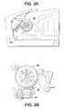
- the drum maintenance fluid can be present in several locations throughout the drum maintenance system, as shown in Figures 3A and 3B , including the surface of the drum maintenance roller 58, metering blade 60, drum surface 62, transfix roller 64, and ultimately on the print media 66 passing through the transfix system. Again, the drum maintenance fluid to be evaluated can be obtained from any of these locations.
- the imaging material comprises a fuser lubricant and at least one fluorescent tag.
- the imaging material is prepared for use with the system and methods described herein.
- the imaging material is prepared to be identified as authentic by the system and methods.
- the tag comprises a fluorescence or scintillation chemical.
- Fluorescent or scintillating materials are those materials exhibiting fluorescence while being acted upon by radiant energy such as ultraviolet (UV) rays or X-rays.
- Suitable materials may be solid or liquid, organic or inorganic, and include, for example, any well-known fluorescent crystals or fluorescent dyes.
- fluorescent dyes have been typically used in tagging molecules in chemical or biochemical research.
- Suitable fluorescent dyes include, for example, fluorescein, rhodamine, rosaline, uranium europium, uranium-sensitized europium, and mixtures thereof. Organic compounds may also be used.
- Those that have been tested to be solvent compatible with fuser fluids include poly(methylphenyl siloxane), 1,4-Bis(4-methyl-5-phenyloxazol-2-yl) benzene, 1,4-Bis(5-phenyl oxazol-2-yl) benzene, 2,5-diphenyl oxazole, 1,4-Bis(2-methylstyryl) benzene, trans-4,4'-diphenyl stilbebene, 9,10-diphenyl anthracene, and mixtures thereof.
- Positions of the fluorescence band for toluene range from about 350 nm to about 420 nm while being radiated with ultraviolet rays having wavelengths of 365 nm.
- the present embodiments also contemplate using fluorescence tags which can fluoresce in all different visible colors, namely from about 350nm to about 700nm.
- the fluorescent material is capable of exhibiting fluorescence in small amounts. Consequently, the fluorescent tag can be added in small amounts to the imaging material without altering the properties or performance of the tagged material.
- the present embodiments provide for a fluorescent tag that is present in the tagged imaging material in an amount of from about 0.001 to about 10,000 ppm, in an amount of from about 0.001 to about 1,000 ppm, or in an amount from about 0.01 to about 100ppm.
- Methods used to "treat" or incorporate the fluorescent tag into the imaging material may be physical in nature, chemical in nature or a combination of both.
- a physical treatment method may involve simple mixing of the fuser fluid with the fluorescent material, or a chemical treatment method may involve bonding the fluorescent tag to the fuser fluid by any suitable technique.
- the tag comprises a fluorescent material that is not sufficiently soluble in the tagged material
- the insolubility can be addressed by modifying the molecule with a moiety compatible with the tagged material.
- the moiety is a short silicone chain.
- a method for authenticating an imaging material comprises tagging an imaging material with the fluorescent tag described above, and measuring the level of fluorescence emitted.
- An energy source such as radiant energy
- the energy source will stimulate an emission of fluorescent light from the fluorescent tag if the evaluated material contains one. Any fluorescence that is stimulated from the evaluated imaging material is measured.
- the measurement may be set at a predetermined wavelength that is set to only pick up fluorescence from the authentic imaging materials. Fluorescence that meets the predetermined values is identified as authentic.
- the method may include subjecting the emission of fluorescent light from the imaging material to a filter to remove background fluorescence or interference before measuring the emission of fluorescent light from the material at the predetermined wavelength.
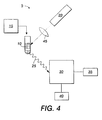
- a system 5 for authenticating an imaging material 10 obtained from an imaging assembly 15 comprises a fluorescent tag used to tag imaging materials used in the imaging assembly.
- the system provides an energy source 20 for stimulating an emission 25 of fluorescent light from the imaging material 10, and a fluorescent detector 30 for measuring the emission 25 of fluorescent light from the imaging material 10 at a predetermined wavelength.
- the energy source 20 could be a cost-effective UV light emitting diode (LED).
- LED UV light emitting diode
- such a UV LED may have a peak emission wavelength of 365nm and a narrow spectrum half width, e.g., 10 nm.
- the fluorescent detector 30 includes an indicator 35 for identifying the evaluated imaging material 10 as authentic when the measured emission 25 of fluorescent light, if any, from the imaging material 10 meets the predetermined wavelength.
- the indicator 35 may be a part of the detector 30, for example, a display screen disposed on the detector.
- the indicator 35 may also be a separate component not attached to the detector, for example, a remote personal computer that remotely communicates with the detector 30 via a wired or wireless network.
- the fluorescent detector 30 detects light within a visible spectrum.
- the detector 30 comprises multiple sensors. In certain arrangements, where the sensors (and their filters) are placed in close proximity to the tagged material, the detector are able to detect the fluorescence of the material without additional optics. However, if other considerations force the detectors to be placed at some distance from the tagged material, then it may be advantageous to also include collection optics between the material being tested and the detector to gather and focus the fluorescent light from the tested material onto the detector(s).
- the system 5 may further include a smart chip 40 coupled to the fluorescence detector 30 for requesting replacement of the evaluated material when the material is not authentic.
- An optical filter 45 may be included in the system 5 to remove background fluorescence or interference that may be involved in the evaluation of the imaging material 10.
- filters may include, for example, an acousto-optic tunable filter, a fiber tunable filter, a thin-film interference filter, or an optical band-pass filter.
- Thin-film filters may be interference filter wheels or interference filter turrets.
- a "digital" filter may be used to distinguish fluorescence from the fluorescent tag from that of other interferences or contaminants that may also cause a test imaging material to fluoresce.
- Digital filtering involves measuring fluorescent intensity in a range of wavelength.
- a plot of intensity versus wavelength shows peaks, each being characterized by a set of fluorescent parameters (e.g., fluorescent wavelength, intensity, and full width at half maximum (FWHM)).
- fluorescent parameters e.g., fluorescent wavelength, intensity, and full width at half maximum (FWHM)
- FWHM full width at half maximum
- Example 3 set forth herein below is illustrative of different compositions and conditions that can be used in practicing the present invention.
- Examples 1 and 2 are reference examples. All proportions are by weight unless otherwise indicated. It will be apparent, however, that the embodiments can be practiced with many types of compositions and can have many different uses in accordance with the disclosure above and as pointed out hereinafter.
- a typical fusing system (e.g., electrostatographic printing system), includes a fuser roll, a pressure roll , a printing medium, an image, a metering roll, a donor roll, a release agent sump, and a fuser fluid or fuser release oil.
- the fuser fluid is treated with a fluorescent tag.
- An ultraviolet lamp is radiated onto the fluorescent tagged fuser fluid in the sump, and fluorescence intensity is measured as a function of wavelength.
- the measured fluorescence spectrum is then fit to a model in which the model parameters are compared with predetermined values, for example, predetermined wavelengths, stored in a fluorescence detection device.
- the fuser fluid is authenticated if the model parameters meet the stored values.
- model parameters are dependent on the location of the detection, for example, where in the fusing system the tested fuser fluid is obtained from, and thereby the parameters are dependent on the amount and temperature of the fuser fluid.
- a typical solid ink jet (SIJ) printing system includes a drum maintenance and imaging cycle. An image on the drum surface is transfixed to a sheet of final substrate by passage through the transfix nip. The drum maintenance roller then cleans and applied drum maintenance fluid to the drum before the image is jetted.
- the drum maintenance fluid is treated with a fluorescent tag. Poly(methylphenyl siloxane), which is readily soluble in typical silicone-based drum maintenance fluids, may be used as the fluorescent tag molecule in this example.
- An ultraviolet lamp is radiated on the fluorescent tagged drum maintenance fluid in the drum maintenance system.
- the fluorescence intensity is measured as a function of wavelength.
- the measured fluorescence spectrum is then fit to a model in which the model parameters are compared with predetermined values, for example, predetermined wavelengths, stored in a fluorescence detection device.
- the drum maintenance fluid is authenticated if the model parameters meet the stored values.
- model parameters are dependent on the location of the detection, for example, where in the drum maintenance system the tested drum maintenance fluid is obtained from, and thereby the parameters are dependent on the amount and temperature of the drum maintenance fluid.
- Fluoranthene (99%), available from Sigma-Aldrich Co. (St. Louis, Missouri) and fluorescent clear blue dye (Invisible Blue), available from Risk Reactor (Huntington Beach, California), were tested as fluorescent tags. It was noted that fluoranthene (99%) was soluble in a variety of organic solvents, and miscible in silicone, while fluorescent clear blue dye had limited solubility in methyl ethyl ketone (MEK).
- MEK methyl ethyl ketone
- the fluoranthene (99%) and fluorescent clear blue dye were first dissolved in appropriate solvents and then added directly to SIJ silicone fluid for evaluation of fluorescent tag effectiveness.
- the following samples were used in the evaluation: (1) 5g of drum maintenance fluid alone, (2) 5g of drum maintenance fluid with 0.2g of 5% fluoranthene in acetone (0.2% of fluoranthene), and (3) 5g of drum maintenance fluid with 0.2g of 5% fluorescent clear blue dye in MEK (0.2% of DFSB-CO).
- the paper substrate also fluoresces under black light.
- using proper filtering techniques before imaging fluorescence signals in the samples would amplify the differences in fluorescence signal between the control sample and samples with fluorescent tags.
- a typical web-cleaning fusing system (e.g., electrostatographic printing system) includes a fuser roll having a TEFLON outer layer.
- a fuser roll generally does not require a fuser release agent.
- the TEFLON outer layer has a very low surface energy (thereby having sufficient release properties), it is still desirable to use a cleaning web for removal of paper dust or a very small quantity of residual toner on the surface.
- the cleaning web is largely improved by impregnated lubricant, such as silicone oil.
- the fuser lubricant is treated with a fluorescent tag.
- An ultraviolet lamp is radiated on the fluorescent tagged drum fuser lubricant in the web-cleaning fusing system.
- the fluorescence intensity is measured as a function of wavelength.
- the measured fluorescence spectrum is then fit to a model in which the model parameters are compared with predetermined values, for example, predetermined wavelengths, stored in a fluorescence detection device.
- the evaluated fuser lubricant is authenticated if the model parameters meet the stored values.
- model parameters are dependent on the location of the detection, for example, where in the web-cleaning fusing system the tested fuser lubricant is obtained from, and thereby the parameters are dependent on the amount and temperature of the fuser lubricant.
Landscapes
- Chemical & Material Sciences (AREA)
- Physics & Mathematics (AREA)
- General Physics & Mathematics (AREA)
- Chemical Kinetics & Catalysis (AREA)
- General Chemical & Material Sciences (AREA)
- Oil, Petroleum & Natural Gas (AREA)
- Organic Chemistry (AREA)
- Investigating, Analyzing Materials By Fluorescence Or Luminescence (AREA)
- Ink Jet (AREA)
- Fixing For Electrophotography (AREA)
Claims (13)
- Procédé d'authentification d'un matériau (10) de formation d'images comprenant le fait :de marquer un matériau (10) de formation d'images avec au moins une étiquette fluorescente, où le matériau (10) de formation d'images est un lubrifiant de fixage, où le lubrifiant de fixage est obtenu d'un emplacement dans un système de fusion (56) sélectionné parmi le groupe se composant d'une bande de nettoyage (48), d'un rouleau de fusion (50), d'un rouleau de pression (52), et d'un support (54) passant à travers le système de fusion (56) de nettoyage par bandes;de générer une source d'énergie (20) pour stimuler une émission (25) de lumière fluorescente à partir du lubrifiant de fixage marqué au fiuorescent ;de stimuler l'émission (25) de lumière fluorescente à partir du lubrifiant de fixage marqué au fluorescent ;de mesurer l'émission (25) de lumière fluorescente à partir du lubrifiant de fixage marqué au fluorescent à une longueur d'onde prédéterminée ; etd'identifier un lubrifiant de fixage test comme authentique lorsque l'émission mesurée (25) de lumière fluorescente à partir du lubrifiant de fixage test rencontre une émission prédéterminée (25) de lumière fluorescente à partir du lubrifiant de fixage marqué au fluorescent à la longueur d'onde prédéterminée ;
- Procédé de la revendication 1, comportant en outre le fait de modifier l'étiquette fluorescente avec un groupe caractéristique chimique compatible avec le lubrifiant de fixage de sorte que l'étiquette fluorescente soit soluble dans le lubrifiant de fixage.
- Procédé de l'une des revendications précédentes, comportant en outre le fait de soumettre l'émission (25) de lumière fluorescente à partir du lubrifiant de fixage marqué au fluorescent à un filtre pour retirer l'interférence de fond avant de mesurer l'émission (25) de lumière fluorescente à partir du lubrifiant de fixage marqué au fluorescent à la longueur d'onde prédéterminée, où le filtre est sélectionné parmi le groupe se composant d'un filtre accordable acousto-optique, d'un filtre accordable à fibres, d'un filtre d'interférence à film mince, d'un filtre passe-bande optique, et d'un filtre numérique.
- Procédé de l'une des revendications précédentes, où l'étiquette fluorescente comprend un colorant sélectionné parmi le groupe se composant de fluorescéine, de rhodamine, d'unionite, d'uranium-europium, d'europium sensible à l'uranium, et de leurs mélanges, et/ou où l'étiquette fluorescente comprend un composant organique sélectionné parmi le groupe constitué de poly(méthylphényl siloxane), de 1,4-Bis(4-méthyl-5-phényloxazol-2-yl)benzène, de 1,4-Bis(5-phényl oxazol-2-yl)benzène, de 2,5-diphényloxazole, de 1,4-Bis(2-méthylstyryl)benzène, de trans-4,4'-diphényl stilbébène, de 9,10-diphényl anthracène, et de leurs mélanges.
- Procédé de l'une des revendications précédentes, où l'étiquette fluorescente est présente dans le matériau (10) de formation d'images en une quantité allant de 0,001 à 10,000 ppm.
- Procédé de la revendication 5, où l'étiquette fluorescente est présente dans le matériau (10) de formation d'images en une quantité allant de 0,001 à 1000 ppm.
- Procédé de la revendication 6, où l'étiquette fluorescente est présente dans le matériau (10) de formation d'images en une quantité allant de 0,01 à 100 ppm.
- Procédé de l'une des revendications précédentes, où la source d'énergie (20) est sélectionnée parmi le groupe se composant de rayons ultraviolets, de rayons X, et de leurs mélanges, et/ou le détecteur (30) de fluorescent détecte la lumière dans un spectre visible.
- Système comprenant un matériau (10) de formation d'images et un appareil d'authentification pour authentifier le matériau (10) de formation d'images, où le matériau (10) de formation d'images est un lubrifiant de fixage, où le lubrifiant de fixage peut être obtenu à partir d'un emplacement dans un système de fusion (56) de nettoyage par bandes sélectionné parmi le groupe de composant d'une bande de nettoyage (48), d'un rouleau de fusion (50), d'un rouleau de pression (52), et d'un support (54) passant à travers le système de fusion (56) de nettoyage par bandes ;
le système comprenant en outre :au moins une étiquette fluorescente pour marquer le lubrifiant de fixage,une source d'énergie (20) pour stimuler une émission (25) de lumière fluorescente à partir du lubrifiant de fixage marqué au fluorescent ; etun détecteur (30) de fluorescent pour mesurer l'émission (25) de lumière fluorescente à partir du lubrifiant de fixage marqué au fluorescent à une longueur d'onde prédéterminée, où le détecteur (30) de fluorescent comporte un indicateur (35) pour identifier un lubrifiant de fixage test comme authentique lorsque l'émission mesurée (25) de lumière fluorescente à partir du lubrifiant de fixage test rencontre une émission prédéterminée (25) de lumière fluorescente à partir du lubrifiant de fixage marqué au fluorescent à la longueur d'onde prédéterminée. - Système (10) de la revendication 9, comprenant en outre les caractéristiques supplémentaires de l'une des revendications 4 à 8.
- Système (10) de la revendication 9, où l'étiquette fluorescente est modifiée avec un groupe caractéristique chimique compatible avec le lubrifiant de fixage de sorte que l'étiquette fluorescente soit soluble dans le lubrifiant de fixage.
- Système (10) de la revendication 9, comportant en outre une puce intelligente (40) couplée au détecteur (30) de fluorescence pour demander le remplacement du lubrifiant de fixage lorsque le lubrifiant de fixage n'est pas authentique.
- Système (10) de la revendication 9, où le détecteur (30) de fluorescent comprend plusieurs détecteurs.
Applications Claiming Priority (1)
| Application Number | Priority Date | Filing Date | Title |
|---|---|---|---|
| US11/726,212 US7715733B2 (en) | 2007-03-21 | 2007-03-21 | System and method for authenticating a fuser lubricant in an image forming apparatus |
Publications (2)
| Publication Number | Publication Date |
|---|---|
| EP1973006A1 EP1973006A1 (fr) | 2008-09-24 |
| EP1973006B1 true EP1973006B1 (fr) | 2010-10-06 |
Family
ID=39532885
Family Applications (1)
| Application Number | Title | Priority Date | Filing Date |
|---|---|---|---|
| EP08102171A Ceased EP1973006B1 (fr) | 2007-03-21 | 2008-02-29 | Systèmes et procédés d'authentification de matériel |
Country Status (5)
| Country | Link |
|---|---|
| US (1) | US7715733B2 (fr) |
| EP (1) | EP1973006B1 (fr) |
| JP (1) | JP2008233083A (fr) |
| CA (1) | CA2625526C (fr) |
| DE (1) | DE602008002845D1 (fr) |
Families Citing this family (7)
| Publication number | Priority date | Publication date | Assignee | Title |
|---|---|---|---|---|
| US8310541B2 (en) * | 2007-09-26 | 2012-11-13 | Xerox Corporation | System and method for monitoring a printing system using a camera |
| US7715008B2 (en) * | 2008-03-21 | 2010-05-11 | Xerox Corporation | System and method of optically monitoring contamination of a machine component |
| EP2431732A1 (fr) | 2010-09-21 | 2012-03-21 | Dow Global Technologies LLC | Association de l'analyse en ligne et de la technologie de traceur |
| AU2015363041B2 (en) | 2014-12-18 | 2018-12-13 | 3M Innovative Properties Company | Batch authentication of materials for automated anti counterfeiting |
| US11386540B2 (en) | 2017-03-31 | 2022-07-12 | 3M Innovative Properties Company | Image based counterfeit detection |
| US11847661B2 (en) | 2017-11-30 | 2023-12-19 | 3M Innovative Properties Company | Image based counterfeit detection |
| WO2020003150A2 (fr) | 2018-06-28 | 2020-01-02 | 3M Innovative Properties Company | Détection de nouveauté à base d'images d'échantillons de matériau |
Family Cites Families (27)
| Publication number | Priority date | Publication date | Assignee | Title |
|---|---|---|---|---|
| US4518655A (en) * | 1983-11-25 | 1985-05-21 | Xerox Corporation | Fusing member for electrostatographic copiers |
| US4929983A (en) * | 1989-04-07 | 1990-05-29 | Xerox Corporation | Stripper mechanism |
| US5045890A (en) * | 1989-04-07 | 1991-09-03 | Xerox Corporation | Fuser apparatus with release agent delivery system |
| US4945250A (en) * | 1989-07-12 | 1990-07-31 | Pb Diagnostic Systems, Inc. | Optical read head for immunoassay instrument |
| JPH04186389A (ja) * | 1990-11-21 | 1992-07-03 | Canon Inc | 定着装置のクリーニング装置 |
| US5166031A (en) * | 1990-12-21 | 1992-11-24 | Xerox Corporation | Material package for fabrication of fusing components |
| JP2974495B2 (ja) * | 1992-04-24 | 1999-11-10 | 株式会社日立製作所 | 電気泳動装置及び電気泳動方法 |
| US5176980A (en) | 1991-08-08 | 1993-01-05 | Eastman Kodak Company | Electrographic liquid developer and method of making same |
| US5805191A (en) * | 1992-11-25 | 1998-09-08 | Tektronix, Inc. | Intermediate transfer surface application system |
| US5389958A (en) * | 1992-11-25 | 1995-02-14 | Tektronix, Inc. | Imaging process |
| US5498808A (en) | 1995-01-20 | 1996-03-12 | United Color Manufacturing, Inc. | Fluorescent petroleum markers |
| US5736250A (en) * | 1996-08-08 | 1998-04-07 | Xerox Corporation | Crosslinked latex polymer surfaces and methods thereof |
| US6002893A (en) * | 1998-01-08 | 1999-12-14 | Xerox Corporation | High and low pigment loadings for custom colors |
| JP2000268223A (ja) * | 1999-03-17 | 2000-09-29 | Seiko Epson Corp | 偽造物の判定方法及びその判定装置 |
| JP2000315032A (ja) * | 1999-04-28 | 2000-11-14 | Ricoh Co Ltd | クリーニング装置 |
| US6176575B1 (en) * | 1999-08-25 | 2001-01-23 | Xerox Corporation | Drum maintenance unit life extension |
| US6716502B1 (en) * | 1999-10-11 | 2004-04-06 | Xerox Corporation | Fuser member coating composition and processes for providing elastomeric surfaces thereon |
| US6677584B2 (en) * | 2001-06-25 | 2004-01-13 | Cummins Inc. | Manufacturing fluid including fluorescent dye penetrant and method for using to make components |
| WO2003004569A1 (fr) | 2001-07-02 | 2003-01-16 | Arctic Diagnostics Oy | Procede permettant d'ameliorer l'hydrophilicite de composes marqueurs fluorescents |
| US6514617B1 (en) * | 2001-07-11 | 2003-02-04 | General Electric Company | Tagging materials for polymers, methods, and articles made thereby |
| JP2003329588A (ja) * | 2002-05-14 | 2003-11-19 | Masaya Fukui | 材料識別方法および材料識別システム並びに材料識別装置 |
| US6876832B2 (en) * | 2003-06-05 | 2005-04-05 | Xerox Corporation | Fuser apparatus having cleaning web spooling prevention |
| US7371524B2 (en) | 2003-06-17 | 2008-05-13 | Hannjorg Hereth | Substituted azaporphyrins as fluorescence labels |
| JP2005128380A (ja) * | 2003-10-27 | 2005-05-19 | Ricoh Co Ltd | 定着装置、画像形成装置、及びこれに使用されるトナー |
| JP2004163963A (ja) * | 2003-12-15 | 2004-06-10 | Casio Electronics Co Ltd | 画像形成装置 |
| ES2426750T3 (es) * | 2005-02-18 | 2013-10-25 | American Dye Source, Inc. | Método para codificar materiales con una etiqueta luminiscente y aparato para leer la misma |
| US7394997B2 (en) | 2005-06-28 | 2008-07-01 | Hewlett-Packard Development Company, L.P. | Anti-counterfeiting identification system and method for consumables |
-
2007
- 2007-03-21 US US11/726,212 patent/US7715733B2/en not_active Expired - Fee Related
-
2008
- 2008-02-29 DE DE602008002845T patent/DE602008002845D1/de active Active
- 2008-02-29 EP EP08102171A patent/EP1973006B1/fr not_active Ceased
- 2008-03-14 JP JP2008065616A patent/JP2008233083A/ja active Pending
- 2008-03-14 CA CA2625526A patent/CA2625526C/fr not_active Expired - Fee Related
Also Published As
| Publication number | Publication date |
|---|---|
| CA2625526A1 (fr) | 2008-09-21 |
| JP2008233083A (ja) | 2008-10-02 |
| US20080231851A1 (en) | 2008-09-25 |
| DE602008002845D1 (de) | 2010-11-18 |
| US7715733B2 (en) | 2010-05-11 |
| EP1973006A1 (fr) | 2008-09-24 |
| CA2625526C (fr) | 2012-05-29 |
Similar Documents
| Publication | Publication Date | Title |
|---|---|---|
| EP1973005B1 (fr) | Systèmes et procédés d'authentification de matériel | |
| EP1973079B1 (fr) | Systèmes et procédés d'authentification de matériel | |
| CA2625526C (fr) | Systemes et methodes d'authentification d'articles | |
| US8759794B2 (en) | Articles, methods of validating the same, and validation systems employing decay constant modulation | |
| EP2805288B1 (fr) | Technique d'authentification et de détection par excitation/émission à multiples longueurs d'onde | |
| AU2003277311A2 (en) | On-line verification of an authentication mark applied to products or product packaging | |
| CN101871890A (zh) | 安全成像系统 | |
| JP2009229466A (ja) | 機械の汚染を光学的に監視するシステム及び方法 | |
| JP3870185B2 (ja) | 陽イオンポリマー定着剤中の検出可能なマーカー | |
| WO2001017784A1 (fr) | Recharge d'impression d'origine et procede | |
| US10088430B2 (en) | Systems and methods for authenticating working fluids | |
| US20080163777A1 (en) | Security Kit and Security Ink | |
| EP3117423B1 (fr) | Composant avec marqueur d'authenticité et indicateur d'utilisation, système ou machine contenant le composant et procédé de contrôle d'un composant | |
| JP2005100003A (ja) | 情報記録媒体 |
Legal Events
| Date | Code | Title | Description |
|---|---|---|---|
| PUAI | Public reference made under article 153(3) epc to a published international application that has entered the european phase |
Free format text: ORIGINAL CODE: 0009012 |
|
| AK | Designated contracting states |
Kind code of ref document: A1 Designated state(s): AT BE BG CH CY CZ DE DK EE ES FI FR GB GR HR HU IE IS IT LI LT LU LV MC MT NL NO PL PT RO SE SI SK TR |
|
| AX | Request for extension of the european patent |
Extension state: AL BA MK RS |
|
| 17P | Request for examination filed |
Effective date: 20090324 |
|
| 17Q | First examination report despatched |
Effective date: 20090423 |
|
| AKX | Designation fees paid |
Designated state(s): DE FR GB |
|
| GRAP | Despatch of communication of intention to grant a patent |
Free format text: ORIGINAL CODE: EPIDOSNIGR1 |
|
| GRAS | Grant fee paid |
Free format text: ORIGINAL CODE: EPIDOSNIGR3 |
|
| GRAA | (expected) grant |
Free format text: ORIGINAL CODE: 0009210 |
|
| AK | Designated contracting states |
Kind code of ref document: B1 Designated state(s): DE FR GB |
|
| REG | Reference to a national code |
Ref country code: GB Ref legal event code: FG4D |
|
| REF | Corresponds to: |
Ref document number: 602008002845 Country of ref document: DE Date of ref document: 20101118 Kind code of ref document: P |
|
| PLBE | No opposition filed within time limit |
Free format text: ORIGINAL CODE: 0009261 |
|
| STAA | Information on the status of an ep patent application or granted ep patent |
Free format text: STATUS: NO OPPOSITION FILED WITHIN TIME LIMIT |
|
| 26N | No opposition filed |
Effective date: 20110707 |
|
| REG | Reference to a national code |
Ref country code: DE Ref legal event code: R097 Ref document number: 602008002845 Country of ref document: DE Effective date: 20110707 |
|
| REG | Reference to a national code |
Ref country code: FR Ref legal event code: PLFP Year of fee payment: 9 |
|
| REG | Reference to a national code |
Ref country code: FR Ref legal event code: PLFP Year of fee payment: 10 |
|
| REG | Reference to a national code |
Ref country code: FR Ref legal event code: PLFP Year of fee payment: 11 |
|
| PGFP | Annual fee paid to national office [announced via postgrant information from national office to epo] |
Ref country code: GB Payment date: 20200123 Year of fee payment: 13 |
|
| PGFP | Annual fee paid to national office [announced via postgrant information from national office to epo] |
Ref country code: FR Payment date: 20200122 Year of fee payment: 13 |
|
| PGFP | Annual fee paid to national office [announced via postgrant information from national office to epo] |
Ref country code: DE Payment date: 20210120 Year of fee payment: 14 |
|
| GBPC | Gb: european patent ceased through non-payment of renewal fee |
Effective date: 20210228 |
|
| PG25 | Lapsed in a contracting state [announced via postgrant information from national office to epo] |
Ref country code: GB Free format text: LAPSE BECAUSE OF NON-PAYMENT OF DUE FEES Effective date: 20210228 Ref country code: FR Free format text: LAPSE BECAUSE OF NON-PAYMENT OF DUE FEES Effective date: 20210228 |
|
| REG | Reference to a national code |
Ref country code: DE Ref legal event code: R119 Ref document number: 602008002845 Country of ref document: DE |
|
| PG25 | Lapsed in a contracting state [announced via postgrant information from national office to epo] |
Ref country code: DE Free format text: LAPSE BECAUSE OF NON-PAYMENT OF DUE FEES Effective date: 20220901 |