EP1973059A2 - Dispositif, procédé et programme de détection de région faciale - Google Patents
Dispositif, procédé et programme de détection de région faciale Download PDFInfo
- Publication number
- EP1973059A2 EP1973059A2 EP08152880A EP08152880A EP1973059A2 EP 1973059 A2 EP1973059 A2 EP 1973059A2 EP 08152880 A EP08152880 A EP 08152880A EP 08152880 A EP08152880 A EP 08152880A EP 1973059 A2 EP1973059 A2 EP 1973059A2
- Authority
- EP
- European Patent Office
- Prior art keywords
- face
- region
- detected
- section
- detecting
- Prior art date
- Legal status (The legal status is an assumption and is not a legal conclusion. Google has not performed a legal analysis and makes no representation as to the accuracy of the status listed.)
- Granted
Links
Images


Classifications
-
- G—PHYSICS
- G06—COMPUTING OR CALCULATING; COUNTING
- G06V—IMAGE OR VIDEO RECOGNITION OR UNDERSTANDING
- G06V40/00—Recognition of biometric, human-related or animal-related patterns in image or video data
- G06V40/10—Human or animal bodies, e.g. vehicle occupants or pedestrians; Body parts, e.g. hands
- G06V40/16—Human faces, e.g. facial parts, sketches or expressions
- G06V40/168—Feature extraction; Face representation
- G06V40/171—Local features and components; Facial parts ; Occluding parts, e.g. glasses; Geometrical relationships
Definitions
- the present invention relates to a face region detecting device, method, and program, and in particular, relates to a face region detecting device, method, and program which detect the position of a predetermined region of a face from an image in which the face is captured.
- the eye search regions are set on the basis of the eye positions which were measured the previous time as described above, if the face moves greatly to the left or right, the eyes will come out of the set eye search regions, and there is therefore the problem that the eyes cannot be detected.
- the present invention has been made in view of the above circumstances and provides a face region detecting device.
- the present invention provides a face region detecting device having: an image capturing section capturing a face of an observed person; a position detecting section detecting, from a face image expressing the face captured by the image capturing section, one of a position expressing a characteristic of a nose and a position expressing a characteristic of a region between eyebrows; a computing section computing a past relative position of a predetermined region of the face that is based on the position detected in the past by the position detecting section; and a region position detecting section detecting a position of the predetermined region on the basis of the past relative position computed by the computing section and the current position detected by the position detecting section.
- a program relating to the present invention is a program that causes a computer to function as: a position detecting section detecting, from a face image expressing a face captured by an image capturing section that captures a face of an observed person, one of a position expressing a characteristic of a nose and a position expressing a characteristic of a region between eyebrows; a computing section computing a past relative position of a predetermined region of the face that is based on the position detected in the past by the position detecting section; and a region position detecting section detecting a position of the predetermined region on the basis of the past relative position computed by the computing section and the current position detected by the position detecting section.
- the face of an observed person is captured by the image capturing section.
- Either one of a position that expresses a characteristic of a nose and a position that expresses a characteristic of a region between the eyebrows is detected by the position detecting section from the face image expressing the face captured by the image capturing section.
- a past relative position of a predetermined region of the face is computed by the computing section.
- the position of the predetermined region is detected by the region position detecting section on the basis of the past relative position computed by the computing section and the current position detected by the position detecting section.
- the position of a predetermined region of the face is detected by using the past relative position, by using as a reference one of the position expressing a characteristic of a nose and a position expressing a characteristic of a region between the eyebrows.
- the position of the predetermined region of the face is thereby detected by using a position expressing a characteristic of the nose or a position expressing a characteristic of the region between the eyebrows, both of which can be detected easily. Therefore, even if the face moves, the position of the predetermined region of the face can be detected by a simple computational processing.
- the face region detecting device of the present invention may further include a candidate detecting section detecting a plurality of candidates for the position of the predetermined region, and the region position detecting section may detect the position of the predetermined region by comparing current relative positions of the respective plurality of candidates that are based on the current position detected by the position detecting section, and the past relative position computed by the computing section. In this way, the past relative position and the candidates for the current relative position are compared, and the current position of the predetermined region can be detected by simple computational processing.
- the region position detecting section relating to the present invention may detect the position of the predetermined region on the basis of the past relative position computed by the computing section, that is based on the current position detected by the position detecting section. In this way, the current position of the predetermined region can be detected by simple computational processing.
- the aforementioned position expressing a characteristic of a nose may be a position of a central point of centers of gravity of left and right nostril regions in the face image. In this way, the current position of the predetermined region can be detected by simple computational processing by using the regions of the left and right nostrils which can be detected easily.
- the aforementioned position of the predetermined region of the face may be a position of an eye
- the position of the eye may be expressed by one of a boundary between an upper eyelid and an eyeball in the face image, a boundary between a lower eyelid and the eyeball in the face image, a center of gravity of a pupil in the face image, and a central point of the boundary between the upper eyelid and the eyeball and the boundary between the lower eyelid and the eyeball.
- the aforementioned position of the predetermined region of the face may be a position of an eye, and the position of the eye may be expressed by a vertical direction position of a boundary between a lower eyelid and an eyeball in the face image, and a left-right direction position of a boundary between an upper eyelid and the eyeball.
- the position of the predetermined region of the face can thereby be expressed with high accuracy.
- a face region detecting method relating to the present invention includes: detecting, from a face image expressing a face captured by an image capturing section that captures a face of an observed person, one of a position expressing a characteristic of a nose and a position expressing a characteristic of a region between eyebrows; computing a past relative position of a predetermined region of the face that is based on the position detected in the past; and detecting a position of the predetermined region on the basis of the computed past relative position and the detected current position.
- the present invention provides a computer readable medium storing a program causing a computer to execute a process for face region detection, the process comprising: detecting, from a face image expressing a face captured by an image capturing section that captures a face of an observed person, one of a position expressing a characteristic of a nose and a position expressing a characteristic of a region between eyebrows; computing a past relative position of a predetermined region of the face that is based on the position detected in the past; and detecting a position of the predetermined region on the basis of the computed past relative position and the detected current position.
- the position of a predetermined region of the face is detected by using the past relative position, by using as a reference one of a position expressing a characteristic of a nose and a position expressing a characteristic of a region between the eyebrows.
- the position of the predetermined region of the face is thereby detected by using a position expressing a characteristic of the nose or a position expressing a characteristic of the region between the eyebrows, both of which can be detected easily. Therefore, the effect is obtained that, even if the face moves, the position of the predetermined region of the face can be detected by a simple computational processing.
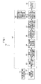
- an eye position detecting device 10 relating to a first exemplary embodiment has an image capturing section 12 formed from a CCD camera or the like and capturing an image including the face of a subject that is the object, an illuminating section 14 formed from an infrared flash, an infrared LED or the like for illuminating the object of photographing synchronously with the operation of a shutter of the image capturing section 12, a computer 16 carrying out image processing, and a display device 18 structured by a CRT or the like.
- the computer 16 is structured to include a CPU, a ROM that stores the program of an image processing routine to be described later, a RAM that stores data and the like, and a bus connecting these. To describe the computer 16 in terms of functional blocks which are divided into respective function realizing sections which are determined on the basis of hardware and software, as shown in Fig.
- the computer 16 has: a image inputting section 20 inputting a face image which is a gray-level image outputted from the image capturing section 12; a nose position detecting section 22 detecting the position of a nose from the face image which is the output of the image inputting section 20; an eye search region setting section 24 setting eye search regions on the basis of the nose position; an eyelid candidate detecting section 26 detecting plural candidates for the positions of the lower eyelids from the images of the eye search regions; a relative position computing section 27 computing the relative positions of the respective candidates for the lower eyelid positions, with respect to the nose position; an eyelid position detecting section 28 detecting, on the basis of the relative positions of the respective candidates for the lower eyelid positions, the positions of the lower eyelids as the eye positions; and a previous relative position storage section 30 storing the relative positions of the eyelid positions with respect to the nose position of the previous time.
- the image inputting section 20 is structured by, for example, an A/D converter, an image memory that stores the image data of one image surface, and the like.
- the nose position detecting section 22 detects the positions of the left and right nostrils (positions expressed by image coordinates) as positions expressing characteristics of the nose from the face image, and detects the image coordinates of the central point of the positions of the left and right nostrils as the nose position.
- a face region F is extracted from the face image.
- the edge of the face contour is computed, or the face contour is extracted by pattern matching of the face contour, and then the face region F is extracted in the range of the face contour.
- the edge of the mouth bottom is detected, and a mouth bottom position M is detected.
- a nostril search region for searching for the nostrils is set.
- a nostril search region N is set within the face region F by using a ratio which is based on the position of the mouth bottom and statistical data.
- the nostril search region N is set at a position which is separated upwardly by a predetermined distance from the detected mouth bottom position M, so as to set the nostril search region in the central portion of the face.
- a rectangular region of a length of 9/16-H and a width of 6/16 ⁇ W is set as the nostril search region N at a position separated by 2/16 ⁇ H upwardly from the mouth bottom position M and a position that is the center of the face region F in the lateral direction.
- two adjacent, substantially circular, dark places are searched for within the range of the nostril search region N, and regions expressing the nostrils are detected.
- horizontal direction edges and vertical direction edges are detected in the range of the nostril search region N.
- a point that changes from light to dark from the left side toward the right side is a vertical positive edge
- a point that changes from dark to light from the left side toward the right side is a vertical negative edge
- a point that changes from light to dark from the upper side toward the lower side is a lateral positive edge
- a point that changes from dark to light from the upper side toward the lower side is a lateral negative edge.
- the region expressing one nostril is detected from a region at which a vertical positive edge appears at the left, a vertical negative edge appears at the right, a lateral positive edge appears at the top, and a lateral negative edge appears at the bottom.
- a region obtained by the above-described positional relationship of these four types of edges is a candidate for a region expressing one nostril.
- the position (a position expressed by image coordinates) of the central point of the centers of gravity of the regions of the left and right nostrils in the face image is detected as the nose position as shown in Fig. 3 .
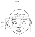
- the eye search region setting section 24 sets the eye search regions by using the detected nose position.
- a right eye search region E and a left eye search region E are set within the face region F on the basis of the detected nose position.
- this smallest range is set as the eye search region. For example, rectangles, at which the vertical and lateral lengths thereof are lengths obtained by multiplying the vertical and lateral lengths of the face region F by a predetermined ratio, are placed above the nose and separated from one another by a predetermined interval, so as to set the eye search regions.
- the right eye search region E and the left eye search region E are rectangles of a length of 0.35W and a width of 0.26W. Then, the two rectangles, which are disposed upward from a position which is separated by 0.08W upward from a center of gravity Cn of the nostrils and which, in the left-right direction, are separated from one another by an interval of 0.13W which is centered with respect to the center of gravity Cn of the nostrils, are set as the right eye search region E and the left eye search region E.
- the eyelid candidate detecting section 26 For each of the right eye image of the right eye search region and the left eye image of the left eye search region, the eyelid candidate detecting section 26 carries out edge processing, and, from the respective edge images of the left and right eyes, extracts edge characteristic points of the edges corresponding to the boundaries between the lower eyelids and the eyeballs (the upper edges of the lower eyelids). On the basis of the extracted edge characteristic points, the eyelid candidate detecting section 26 detects candidates for the lower eyelid positions (candidates for positions expressed by image coordinates) for the left and right eyes respectively. The extraction of the edge characteristic points is carried out as follows.
- the eyelid candidate detecting section 26 generates Sobel edge images by using the Sobel operator for example, from each of the right eye image of the right eye search region and the left eye image of the left eye search region shown in Fig. 5A .
- the generated Sobel edge images express the magnitude of the change in gray level per pixel in the direction from top to bottom in the direction of blinking.
- the changes in the magnitudes of the pixel value changes of the original images in the direction from top to bottom which is the blinking direction are obtained from the generated Sobel edge images.
- the reflectance of the eyeball portion is low and the eyeball portion is photographed as dark, as compared with the eyelid which is a skin portion. Accordingly, in the vicinity of the boundary between the upper eyelid and the eyeball, the pixel values change from light to dark from the top toward the bottom. Further, in a vicinity of the boundary between the lower eyelid and the eyeball, the pixel values change from dark to light from the top toward the bottom.
- the obtained edge values expressing the pixel value changes are greater than or equal to a positive predetermined value at the boundary portion between the eyeball and the upper eyelid, and the edge value of the center of the boundary portion is the maximum value. Further, at the boundary portion between the eyeball and the lower eyelid, the edge values are less than or equal to a negative predetermined value, and the edge value of the center of the boundary portion is the minimum value.
- the edge value of the pixel of interest is the minimum value in the blinking direction. If, on the basis of the edge values of the pixel one above the pixel of interest, and of the pixel of interest, and of the pixel one below the pixel of interest, it is judged that the edge value of the pixel of interest is the minimum value, the position of that pixel of interest is detected as an edge characteristic point. In this way, an edge characteristic point, which shows the edge of the boundary between the lower eyelid and the eyeball, is detected.
- edge characteristic points showing the edge of the boundary between the lower eyelid and the eyeball are detected, it suffices to select the edge characteristic point which shows the edge of the boundary between the lower eyelid and the eyeball, on the basis of the relative positions of the edge characteristic points that are based on the positions of the nostrils.
- the relative position computing section 27 computes, for the left and right eyes respectively, respective relative positions of the image coordinates of the candidates for the lower eyelid positions (relative positions expressed by image coordinates), that are based on the image coordinates of the detected nose position.
- the eyelid position detecting section 28 compares the respective relative positions of the detected plural candidates for the lower eyelid positions, and the relative positions of the lower eyelid positions which are based on the nose position of the previous time.
- the eyelid position detecting section 28 detects the image coordinates of the current eyelid positions as the eye positions, and computes time-sequence correspondences of the eye positions for the left and right eyes respectively.
- the face image of the subject is captured continuously by the image capturing section 12.
- the face portion of the subject is illuminated by, for example, causing the illuminating section 14 which is formed from an infrared flash to emit light synchronously with the photographing of the image capturing section 12. Note that if continuous light is emitted from the illuminating section 14, synchronization with the image capturing section 12 becomes unnecessary and the structure is simplified.
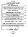
- step 100 the face image which is captured at the image capturing section 12 is taken-in as a video signal.
- step 102 the video signal is A/D converted such that a two-dimensional digital image is generated.
- the processings hereinafter are carried out by digital processing on the basis of this digital image. Therefore, when simply the term "image” is used hereinafter, it means the digital image.
- step 104 the regions showing the left and right nostrils are detected from the face image, and the position of the central point of the centers of gravity of the regions showing the respective left and right nostrils is detected as the nose position.
- step 106 regions, which exist at predetermined positions and whose reference position is the nose position detected in above step 104, are set as the right eye search region and the left eye search region.
- step 108 edge processing is carried out on both the image of the right eye search region and the image of the left eye search region.
- plural image coordinates (candidate x, candidate y) of candidates for the lower eyelid positions are detected.
- respective relative positions (relative x, relative y) of the plural candidates for the lower eyelid positions, which are based on the nose position (nose x, nose y) are computed on the basis of the following formula, for the left and right eyes respectively.
- step 112 for the left and right eyes respectively, the relative positions of the previous time which are stored in the previous relative position storing section 30, and the relative positions computed in above step 110, are compared, and the relative positions which are nearest to the relative positions of the previous time are selected. Then, the nose position is made to be the reference position, and positions which are expressed from the reference position and the selected relative positions are detected as the positions of the lower eyelids.
- step 114 for the left and right eyes respectively, the relative positions selected in above step 112, i.e., the relative positions of the eyelid positions detected in step 112 which are based on the nose position detected in step 104, are stored in the previous relative position storing section 30 and the relative positions of the previous time are updated.
- step 116 by using the lower eyelid positions detected in step 112, temporal correspondences of the eye positions are displayed on the display device 18 for the left and right eyes respectively.
- step 118 it is judged whether or not tracking processing is to be ended. If it is not to be ended, the routine returns to step 100, and the processings of above-described steps 100 through 116 are executed on the basis of the face image which is newly captured. When it is judged in step 118 that the tracking processing is to be ended, the image processing routine ends.
- the eye positions are detected by comparing candidates for the current relative positions and the relative positions of the previous time, by using a position showing a characteristic of the nose as a reference.
- the eye positions are detected by using a position which shows a characteristic of the nose, which position has a high rate of detection and can be detected more easily than the eye positions. Therefore, even if the face moves, the eye positions can be detected and tracked by simple computational processing.
- the temporal correspondences of the eye positions can be obtained without using an eyelid pattern correlation computing system whose cost of computation is high. Further, the temporal correspondences can be obtained correctly even in cases in which the face moves.
- the eye positions can be detected correctly by detecting, as the eye positions, the positions of the boundaries of the lower eyelids whose vertical positions do not move much even when blinking.
- the present invention is not limited to the same.
- the position of the boundary of the upper eyelid and the eyeball in the face image i.e., the lower edge of the upper eyelid
- the center of gravity of the pupil in the face image i.e., the center of gravity of the pupil in the face image
- the central point of the boundary between the upper eyelid and the eyeball and the boundary between the lower eyelid and the eyeball may be detected as the eye position.
- the average density value i.e., the average value of the brightness
- the average density value i.e., the average value of the brightness
- a nostril search start point may be detected by using a black pixel judgment threshold value th corresponding to the computed average density value, and plural search circles which are centered around the nostril search start point and become nostril candidates may be detected, and a pair of circles corresponding to one set of nostrils may be detected as regions showing nostrils.
- the positions of the nostrils may be detected as follows: a white-black-white transverse edge, which is an edge that extends along the transverse direction and changes from white to black and then from black to white, is detected. A black pixel row, which is within the nostril region and whose width is two to three pixels, is detected in the vertical direction. A white-black-white transverse edge, which is an edge that extends along the vertical direction and changes from white to black and then from black to white, is detected. A black pixel row, which is within the nostril region and whose width is two to three pixels, is detected in the transverse direction. The position of a nostril is thereby detected.
- the second exemplary embodiment differs from the first exemplary embodiment with regard to the point that the position between the eyebrows is detected as the reference position of the relative positions.
- a computer 216 of an eye position detecting device 210 relating to the second exemplary embodiment has: the image inputting section 20; a between-eyebrow position detecting section 222 detecting a between-eyebrow position from the face image which is the output of the image inputting section 20; an eye search region setting section 224 setting eye search regions on the basis of the detected between-eyebrow position; the eyelid candidate detecting section 26; a relative position computing section 227 computing the relative positions of the respective candidates for the lower eyelid positions, with respect to the between-eyebrow position; the eyelid position detecting section 28; and a previous relative position storing section 230 storing the relative positions of the lower eyelid positions which are based on the between-eyebrow position of the previous time.
- the between-eyebrow position detecting section 222 detects the between-eyebrow position, which shows a characteristic of the region between the eyebrows, from the face image as follows.
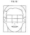
- a filter that detects the region between the eyebrows such as shown in Fig. 9 for example, in which six rectangular shapes are joined together, is used.
- This between-eyebrow detecting filter which is a six-segmented rectangular filter extracts the characteristics of the face that the bridge of the nose is brighter than the both eye regions and the eye regions are darker than the cheeks, and determines a position that shows the characteristic of the region between the eyebrows of the face.
- the between-eyebrow detecting filter has a rectangular frame which is centered around a point (x,y) and which is i pixels transversely (i is a natural number) and j pixels vertically (j is a natural number). Then, as shown in Fig. 10 , the between-eyebrow detecting filter is applied to the face image, and positions of between-eyebrow candidate points are extracted by filtering processing. Then, an object image is cut-out to a predetermined size with the extracted position of the between-eyebrow candidate point being the center, pattern determination processing is carried out, the true candidate point is selected from among the between-eyebrow candidate points, and the between-eyebrow position is detected.
- the eye search region setting section 224 sets a face region in the face image, and sets a right eye search region and a left eye search region within the face region on the basis of the detected between-eyebrow position. For example, rectangles, at which the vertical and lateral lengths thereof are lengths obtained by multiplying the vertical and lateral lengths of the face region by a predetermined ratio, are set at the right and the left of the detected between-eyebrow position and separated from one another by a predetermined interval, and are made to be the right eye search region and the left eye search region.
- the relative position computing section 27 computes, for the left and right eyes respectively, respective relative positions of the candidates for the lower eyelid positions which are based on the detected between-eyebrow position.
- the relative positions of the lower eyelid positions of the previous time which are based on the between-eyebrow position which was detected the previous time, are stored in the previous relative position storing section 230 for the left and right eyes respectively.
- the between-eyebrow position is detected from the face image, and, by using the detected between-eyebrow position as the reference position, regions existing at predetermined positions are set as the right eye search region and the left eye search region. Then, plural candidates for the lower eyelid position are detected from each of the image of the right eye search region and the image of the left eye search region. Relative positions of the between-eyebrow position and the respective candidates for the lower eyelid position are computed for each of the left and right eyes. The relative positions of the previous time, which are stored in the previous relative position storing section 230, and the computed relative positions are compared with one another for the left and right eyes respectively, and the relative positions which are nearest to the relative positions of the previous time are selected. The detected current between-eyebrow position is used as the reference position, and positions which are expressed from the reference position and the selected relative positions are detected as the positions of the lower eyelids.
- the detected relative positions of the lower eyelid positions which are based on the detected between-eyebrow position, are stored in the previous relative position storing section 230 and the relative positions of the previous time are updated.
- the eye positions By detecting the eye positions in this way by comparing the candidates for the current relative positions with the relative positions of the previous time by using a position expressing a characteristic of the region between the eyebrows as a reference, the eye positions are detected by using a position expressing a characteristic of the region between the eyebrows which is easier to detect than the eye positions and whose detection rate is high. Therefore, even if the face moves, the eye positions can be detected and tracked by simple computational processing.
- a third exemplary embodiment will be described next. Note that structural portions which are similar to those of the first exemplary embodiment are denoted by the same reference numerals, and description thereof is omitted.
- the third exemplary embodiment differs from the first exemplary embodiment with regard to the point that the eye search regions are set on the basis of the nose position and the relative positions of the lower eyelids the previous time.
- a computer 316 of an eye position detecting device 310 relating to the third exemplary embodiment has: the image inputting section 20; the nose position detecting section 22; an eye search region setting section 324 that sets the eye search regions on the basis of the nose position and the relative positions of the lower eyelids the previous time; an eyelid position detecting section 326 that detects the positions of the lower eyelids from the eye search regions; a relative position computing section 328 that computes the relative positions of the detected lower eyelid positions which are based on the nose position; and the previous relative position storing section 30.
- step 100 the face image which is captured at the image capturing section 12 is taken-in as a video signal.
- step 102 the video signal is A/D converted such that a two-dimensional digital image is generated.
- step 104 the regions showing the left and right nostrils are detected from the face image, and the position of the central point of the centers of gravity of the regions showing the respective left and right nostrils is detected as the nose position.
- next step 350 by using the nose position, which was detected in above-described step 104, as the reference position, small regions, which are centered around a position expressed by the reference position and the relative positions of the previous time stored in the previous relative position storing section 30, are set as the left eye search region and the right eye search region.
- step 352 edge processing is carried out on the image of the right eye search region and the image of the left eye search region, and edge characteristic points are detected on the basis of the obtained edge images of the left and right eyes.
- the lower eyelid positions are detected as the eye positions for the left and right eyes respectively.
- the relative positions of the lower eyelid positions detected in step 352, which are based on the nose position detected in step 104, are computed for the left and right eyes respectively.
- the relative positions computed in step 354 are stored in the previous relative position storing section 30, and the relative positions of the previous time are updated for the left and right eyes respectively.
- step 116 by using the lower eyelid positions detected in step 352, temporal correspondences of the eye positions are displayed on the display device 18 for the left and right eyes respectively.
- step 118 it is judged whether or not tracking processing is to be ended. If it is not to be ended, the routine returns to step 100, and the above-described processings are executed on the basis of the face image which is newly captured. When it is judged in step 118 that the tracking processing is to be ended, the image processing routine ends.
- a position expressing a characteristic of the nose is made to be the reference, and the eye positions are detected by using the relative positions of the previous time.
- the eye positions are thereby detected by using a position expressing a characteristic of the nose, which is easier to detect than the eye positions and which has a high detection rate. Therefore, even if the face moves, the eye positions can be detected and tracked by simple computational processing.
- the eye search regions can be specified by setting the eye search regions at positions expressed by the reference position, which is the nose position, and the relative positions of the previous time. Therefore, the eye positions can be detected by a simple computational processing.
- a fourth exemplary embodiment will be described next. Note that the structure of the eye position detecting device relating to the fourth exemplary embodiment is similar to that of the first exemplary embodiment. Thus, the same reference numerals are used therefor, and description thereof is omitted.
- the fourth exemplary embodiment differs from the first exemplary embodiment with regard to the point that an eye position, which is expressed by the vertical direction position of the boundary of the lower eyelid and the left-right direction position of the boundary of the upper eyelid, is detected.
- edge characteristic points which express the boundary between the upper eyelid and the eyeball, are detected from the edge image of the eye search region. Then, the edge characteristic point, that corresponds to the inflection point of the curve showing the boundary of the upper eyelid at the time when the eye is open, is extracted from the detected edge characteristic points, and the left-right direction position of the extracted edge characteristic point is detected. Further, edge characteristic points, which express the boundary between the lower eyelid and the eyeball, are detected from the edge image of the eye search region. The vertical direction position of the boundary between the lower eyelid and the eyeball is detected from the detected edge characteristic points.
- the vertical direction position of the boundary between the lower eyelid and the eyeball is detected as the vertical direction position of the eye position. The eye position is thereby detected.
- the edge maximum point In detecting the position of the upper eyelid, the edge maximum point, whose edge value is greater than or equal to a positive predetermined value and whose edge value is the maximum value, is searched for on the basis of the edge image. It suffices to detect the edge maximum point, which is found above the position of the lower eyelid, as the edge characteristic point showing the boundary between the upper eyelid and the eyeball. Further, there is the possibility that the edge maximum point showing the iris will be detected above the position of the lower eyelid. However, a positive threshold value is provided for the edge value of the detected edge characteristic point, and it suffices to exclude the edge maximum point that shows the iris.
- the upper eyelid When the eye is opened, the upper eyelid is curved roundly, and determining a representative position in the left-right direction is easier at the upper eyelid than at the lower eyelid. Accordingly, by detecting the left-right direction position of the inflection point of the boundary of the upper eyelid as described above, the left-right direction position of the eye position can be detected easily. Further, because the lower eyelid is close to rectilinear, the vertical direction position of the eye position can be easily detected by detecting the vertical direction position of the boundary of the lower eyelid.
- the present invention is not limited to the same.
- the position of eyeglasses, or the position of a predetermined region of the face such as the position of the mouth, the position of the eyebrow, the position of the jaw, the position of the ear, or the like may be detected.
- an edge image which shows the magnitudes of the changes in the gray levels is generated from the gray-level image inputted at the image inputting section.
- the image which is inputted at the image inputting section may be a color image. In this case, it suffices to generate an edge image which shows the magnitudes of the changes in the density values of the color image.
- the present invention is not limited to the same.
- the point where the edge value of the edge image is the maximum value may be detected as the edge characteristic point on the edge of the lower eyelid
- the point where the edge value is the minimum value may be detected as the edge characteristic point on the edge of the upper eyelid.
- An image capturing section captures a face of an observed person.
- a position detecting section detects, from a face image expressing the face captured by the image capturing section, one of a position expressing a characteristic of a nose and a position expressing a characteristic of a region between eyebrows.
- a computing section computes a past relative position of a predetermined region of the face that is based on the position detected in the past by the position detecting section.
- a region position detecting section detects a position of the predetermined region on the basis of the past relative position computed by the computing section and the current position detected by the position detecting section.
Landscapes
- Engineering & Computer Science (AREA)
- Health & Medical Sciences (AREA)
- Oral & Maxillofacial Surgery (AREA)
- General Health & Medical Sciences (AREA)
- Physics & Mathematics (AREA)
- Human Computer Interaction (AREA)
- Computer Vision & Pattern Recognition (AREA)
- General Physics & Mathematics (AREA)
- Multimedia (AREA)
- Theoretical Computer Science (AREA)
- Image Processing (AREA)
- Image Analysis (AREA)
- Length Measuring Devices By Optical Means (AREA)
Applications Claiming Priority (1)
| Application Number | Priority Date | Filing Date | Title |
|---|---|---|---|
| JP2007071524A JP4307496B2 (ja) | 2007-03-19 | 2007-03-19 | 顔部位検出装置及びプログラム |
Publications (3)
| Publication Number | Publication Date |
|---|---|
| EP1973059A2 true EP1973059A2 (fr) | 2008-09-24 |
| EP1973059A3 EP1973059A3 (fr) | 2013-03-06 |
| EP1973059B1 EP1973059B1 (fr) | 2015-04-22 |
Family
ID=39405080
Family Applications (1)
| Application Number | Title | Priority Date | Filing Date |
|---|---|---|---|
| EP20080152880 Active EP1973059B1 (fr) | 2007-03-19 | 2008-03-18 | Dispositif, procédé et programme de détection de région faciale |
Country Status (4)
| Country | Link |
|---|---|
| US (1) | US7916904B2 (fr) |
| EP (1) | EP1973059B1 (fr) |
| JP (1) | JP4307496B2 (fr) |
| CN (1) | CN101271517B (fr) |
Cited By (2)
| Publication number | Priority date | Publication date | Assignee | Title |
|---|---|---|---|---|
| EP2860663A3 (fr) * | 2013-10-09 | 2015-06-03 | Aisin Seiki Kabushiki Kaisha | Appareil pour détecter une partie de l'oeil |
| CN111444748A (zh) * | 2019-01-17 | 2020-07-24 | 北京字节跳动网络技术有限公司 | 一种坐姿检测方法、装置、设备及存储介质 |
Families Citing this family (39)
| Publication number | Priority date | Publication date | Assignee | Title |
|---|---|---|---|---|
| JP4137969B2 (ja) * | 2006-12-04 | 2008-08-20 | アイシン精機株式会社 | 眼部検出装置、眼部検出方法及びプログラム |
| TW200930069A (en) * | 2007-12-21 | 2009-07-01 | Altek Corp | Method for correcting red-eye |
| US8345922B2 (en) * | 2008-09-03 | 2013-01-01 | Denso Corporation | Apparatus for detecting a pupil, program for the same, and method for detecting a pupil |
| WO2011067788A2 (fr) * | 2009-12-02 | 2011-06-09 | Tata Consultancy Services Limited | Système et procédé économique et fiable de suivi du regard et d'identification de l'état de somnolence d'un conducteur |
| JP5554987B2 (ja) * | 2009-12-28 | 2014-07-23 | キヤノン株式会社 | オブジェクト識別装置及びその制御方法 |
| KR20120057033A (ko) * | 2010-11-26 | 2012-06-05 | 한국전자통신연구원 | Iptv 제어를 위한 원거리 시선 추적 장치 및 방법 |
| KR20120113579A (ko) * | 2011-04-05 | 2012-10-15 | 현대자동차주식회사 | 길안내 정보의 윈드쉴드 표시 장치 및 그 방법 |
| DE102011081391A1 (de) * | 2011-08-23 | 2013-02-28 | Robert Bosch Gmbh | Verfahren und Vorrichtung zum Erkennen von Störobjekten in der Umgebungsluft eines Fahrzeugs |
| JP5367037B2 (ja) * | 2011-09-26 | 2013-12-11 | 本田技研工業株式会社 | 顔向き検出装置 |
| US9082004B2 (en) | 2011-12-15 | 2015-07-14 | The Nielsen Company (Us), Llc. | Methods and apparatus to capture images |
| US8861802B2 (en) * | 2012-03-13 | 2014-10-14 | Honeywell International Inc. | Face image prioritization based on face quality analysis |
| US9449412B1 (en) | 2012-05-22 | 2016-09-20 | Image Metrics Limited | Adaptive, calibrated simulation of cosmetic products on consumer devices |
| US9104908B1 (en) | 2012-05-22 | 2015-08-11 | Image Metrics Limited | Building systems for adaptive tracking of facial features across individuals and groups |
| US9460462B1 (en) | 2012-05-22 | 2016-10-04 | Image Metrics Limited | Monetization using video-based simulation of cosmetic products |
| US9111134B1 (en) | 2012-05-22 | 2015-08-18 | Image Metrics Limited | Building systems for tracking facial features across individuals and groups |
| US9129147B1 (en) | 2012-05-22 | 2015-09-08 | Image Metrics Limited | Optimal automatic capture of facial movements and expressions in video sequences |
| TWI498857B (zh) * | 2012-09-14 | 2015-09-01 | Utechzone Co Ltd | 瞌睡提醒裝置 |
| US8769557B1 (en) | 2012-12-27 | 2014-07-01 | The Nielsen Company (Us), Llc | Methods and apparatus to determine engagement levels of audience members |
| US9070015B2 (en) * | 2013-02-07 | 2015-06-30 | Ittiam Systems (P) Ltd. | System and method for iris detection in digital images |
| JP6261206B2 (ja) * | 2013-06-28 | 2018-01-17 | キヤノン株式会社 | 情報処理装置、情報処理方法及びプログラム |
| JP6304999B2 (ja) | 2013-10-09 | 2018-04-04 | アイシン精機株式会社 | 顔検出装置、方法およびプログラム |
| JP6227996B2 (ja) * | 2013-12-18 | 2017-11-08 | 浜松ホトニクス株式会社 | 計測装置及び計測方法 |
| JP6535223B2 (ja) * | 2015-05-28 | 2019-06-26 | 浜松ホトニクス株式会社 | 瞬目計測方法、瞬目計測装置、及び瞬目計測プログラム |
| KR102591552B1 (ko) | 2015-08-21 | 2023-10-18 | 매직 립, 인코포레이티드 | 눈 포즈 측정을 사용한 눈꺼풀 형상 추정 |
| EP3337383B1 (fr) * | 2015-08-21 | 2024-10-16 | Magic Leap, Inc. | Estimation de forme de paupière |
| EP3761232B1 (fr) | 2015-10-16 | 2025-12-03 | Magic Leap, Inc. | Identification de la position de l'oeil à l'aide de caractéristiques de l'oeil |
| US9984282B2 (en) * | 2015-12-10 | 2018-05-29 | Perfect Corp. | Systems and methods for distinguishing facial features for cosmetic application |
| JP2017202038A (ja) * | 2016-05-10 | 2017-11-16 | 富士通株式会社 | 判別装置、判別方法、および判別プログラム |
| US10157323B2 (en) * | 2016-08-30 | 2018-12-18 | Qualcomm Incorporated | Device to provide a spoofing or no spoofing indication |
| JP6973928B2 (ja) * | 2017-11-10 | 2021-12-01 | アルパイン株式会社 | 瞼開閉判定装置および眠気検知装置 |
| CN107944393B (zh) * | 2017-11-27 | 2021-03-30 | 电子科技大学 | 人脸鼻尖定位方法 |
| JP6919619B2 (ja) * | 2018-04-12 | 2021-08-18 | オムロン株式会社 | 画像解析装置、方法およびプログラム |
| US10949649B2 (en) | 2019-02-22 | 2021-03-16 | Image Metrics, Ltd. | Real-time tracking of facial features in unconstrained video |
| US11711638B2 (en) | 2020-06-29 | 2023-07-25 | The Nielsen Company (Us), Llc | Audience monitoring systems and related methods |
| US11195301B1 (en) * | 2020-07-26 | 2021-12-07 | Nec Corporation Of America | Estimation of head yaw in an image |
| US12356286B2 (en) | 2021-07-22 | 2025-07-08 | The Nielsen Company (Us), Llc | Methods, apparatus, and articles of manufacture to locate persons based on adjustable signal strength thresholds |
| US11860704B2 (en) | 2021-08-16 | 2024-01-02 | The Nielsen Company (Us), Llc | Methods and apparatus to determine user presence |
| US11758223B2 (en) | 2021-12-23 | 2023-09-12 | The Nielsen Company (Us), Llc | Apparatus, systems, and methods for user presence detection for audience monitoring |
| US12088882B2 (en) | 2022-08-26 | 2024-09-10 | The Nielsen Company (Us), Llc | Systems, apparatus, and related methods to estimate audience exposure based on engagement level |
Citations (5)
| Publication number | Priority date | Publication date | Assignee | Title |
|---|---|---|---|---|
| JP2000067225A (ja) | 1998-08-26 | 2000-03-03 | Nissan Motor Co Ltd | 眼位置検出装置 |
| JP2001307076A (ja) | 2000-04-24 | 2001-11-02 | Niles Parts Co Ltd | 眼の状態検出装置、居眠り検出装置 |
| JP3312562B2 (ja) | 1996-07-18 | 2002-08-12 | 日産自動車株式会社 | 居眠り状態検出装置 |
| US6606397B1 (en) | 1999-05-25 | 2003-08-12 | Mitsubishi Denki Kabushiki Kaisha | Face image processing apparatus for extraction of an eye image based on the position of the naris |
| JP3444115B2 (ja) | 1996-11-13 | 2003-09-08 | 日産自動車株式会社 | 居眠り状態検出装置 |
Family Cites Families (24)
| Publication number | Priority date | Publication date | Assignee | Title |
|---|---|---|---|---|
| JP2932551B2 (ja) | 1989-12-28 | 1999-08-09 | 日産自動車株式会社 | 虹彩位置検出装置及び運転者の状態検出装置 |
| FR2690822B1 (fr) * | 1992-05-06 | 1994-08-05 | Dior Christian Parfums | Procede de maquillage du visage, en particulier des yeux, et dispositif pour sa mise en óoeuvre. |
| JP3063504B2 (ja) | 1993-12-22 | 2000-07-12 | 日産自動車株式会社 | 画像データの特徴量検出装置 |
| JP3143819B2 (ja) | 1994-05-20 | 2001-03-07 | 株式会社豊田中央研究所 | まぶたの開度検出装置 |
| JP3533722B2 (ja) | 1994-09-30 | 2004-05-31 | オムロン株式会社 | 不良検査方法およびその装置 |
| JPH1044824A (ja) | 1996-07-30 | 1998-02-17 | Nissan Motor Co Ltd | 車両運転者の開閉眼判定装置 |
| JP3422183B2 (ja) | 1996-08-22 | 2003-06-30 | トヨタ自動車株式会社 | 顔画像における目の検出方法 |
| JP3529954B2 (ja) * | 1996-09-05 | 2004-05-24 | 株式会社資生堂 | 顔だち分類法及び顔だちマップ |
| JPH1139469A (ja) * | 1997-07-24 | 1999-02-12 | Mitsubishi Electric Corp | 顔画像処理装置 |
| JPH1166320A (ja) | 1997-08-12 | 1999-03-09 | Mitsubishi Electric Corp | 目画像追跡装置 |
| JP2000123188A (ja) | 1998-10-20 | 2000-04-28 | Toyota Motor Corp | 眼開閉判定装置 |
| JP2000137792A (ja) | 1998-10-30 | 2000-05-16 | Toyota Motor Corp | 眼部検出装置 |
| US6130617A (en) * | 1999-06-09 | 2000-10-10 | Hyundai Motor Company | Driver's eye detection method of drowsy driving warning system |
| ES2199095T3 (es) * | 1999-10-21 | 2007-03-16 | Technolas Gmbh Ophthalmologische Systeme | Reconocimiento y seguimiento del iris para el tratamiento optico. |
| EP1314132B1 (fr) * | 2000-06-27 | 2010-02-17 | Rami Orpaz | Procede et systeme de visualisation de maquillage et d'accessoires de mode |
| JP4469476B2 (ja) * | 2000-08-09 | 2010-05-26 | パナソニック株式会社 | 眼位置検出方法および眼位置検出装置 |
| US7079158B2 (en) * | 2000-08-31 | 2006-07-18 | Beautyriot.Com, Inc. | Virtual makeover system and method |
| KR100856169B1 (ko) * | 2000-12-26 | 2008-09-03 | 가부시키가이샤 시세이도 | 마스카라 선정방법, 마스카라 선정 시스템 및 마스카라카운셀링 툴 |
| US7058209B2 (en) * | 2001-09-20 | 2006-06-06 | Eastman Kodak Company | Method and computer program product for locating facial features |
| JP4789408B2 (ja) * | 2003-06-30 | 2011-10-12 | 株式会社 資生堂 | 目の形態分類方法及び形態分類マップ並びに目の化粧方法 |
| JP4390487B2 (ja) | 2003-07-03 | 2009-12-24 | セコム株式会社 | 頭部領域抽出装置 |
| JP4506250B2 (ja) | 2004-04-12 | 2010-07-21 | 日産自動車株式会社 | 上瞼検出装置 |
| JP4130820B2 (ja) | 2004-08-27 | 2008-08-06 | 株式会社豊田中央研究所 | 顔中心位置検出装置及び方法並びにプログラム |
| US8249695B2 (en) * | 2006-09-29 | 2012-08-21 | Tearscience, Inc. | Meibomian gland imaging |
-
2007
- 2007-03-19 JP JP2007071524A patent/JP4307496B2/ja active Active
-
2008
- 2008-03-17 CN CN2008100850763A patent/CN101271517B/zh active Active
- 2008-03-18 US US12/050,620 patent/US7916904B2/en active Active
- 2008-03-18 EP EP20080152880 patent/EP1973059B1/fr active Active
Patent Citations (5)
| Publication number | Priority date | Publication date | Assignee | Title |
|---|---|---|---|---|
| JP3312562B2 (ja) | 1996-07-18 | 2002-08-12 | 日産自動車株式会社 | 居眠り状態検出装置 |
| JP3444115B2 (ja) | 1996-11-13 | 2003-09-08 | 日産自動車株式会社 | 居眠り状態検出装置 |
| JP2000067225A (ja) | 1998-08-26 | 2000-03-03 | Nissan Motor Co Ltd | 眼位置検出装置 |
| US6606397B1 (en) | 1999-05-25 | 2003-08-12 | Mitsubishi Denki Kabushiki Kaisha | Face image processing apparatus for extraction of an eye image based on the position of the naris |
| JP2001307076A (ja) | 2000-04-24 | 2001-11-02 | Niles Parts Co Ltd | 眼の状態検出装置、居眠り検出装置 |
Cited By (4)
| Publication number | Priority date | Publication date | Assignee | Title |
|---|---|---|---|---|
| EP2860663A3 (fr) * | 2013-10-09 | 2015-06-03 | Aisin Seiki Kabushiki Kaisha | Appareil pour détecter une partie de l'oeil |
| US9646215B2 (en) | 2013-10-09 | 2017-05-09 | Aisin Seiki Kabushiki Kaisha | Eye part detection apparatus |
| CN111444748A (zh) * | 2019-01-17 | 2020-07-24 | 北京字节跳动网络技术有限公司 | 一种坐姿检测方法、装置、设备及存储介质 |
| CN111444748B (zh) * | 2019-01-17 | 2021-11-26 | 北京字节跳动网络技术有限公司 | 一种坐姿检测方法、装置、设备及存储介质 |
Also Published As
| Publication number | Publication date |
|---|---|
| US7916904B2 (en) | 2011-03-29 |
| JP4307496B2 (ja) | 2009-08-05 |
| EP1973059A3 (fr) | 2013-03-06 |
| US20080232650A1 (en) | 2008-09-25 |
| EP1973059B1 (fr) | 2015-04-22 |
| CN101271517A (zh) | 2008-09-24 |
| JP2008234208A (ja) | 2008-10-02 |
| CN101271517B (zh) | 2012-09-19 |
Similar Documents
| Publication | Publication Date | Title |
|---|---|---|
| EP1973059B1 (fr) | Dispositif, procédé et programme de détection de région faciale | |
| JP4845698B2 (ja) | 眼部検出装置、眼部検出方法及びプログラム | |
| JP3761059B2 (ja) | ヒトの顔を検出する方法および装置、ならびに観察者トラッキングディスプレイ | |
| EP1970839B1 (fr) | Appareil, procédé et programme pour effectuer une détection de point caractéristiques | |
| EP1426898B1 (fr) | Détection de personnes par détection de visage et détection de mouvement | |
| JP4895847B2 (ja) | 瞼検出装置及びプログラム | |
| EP1969993B1 (fr) | Appareil de détection de paupière | |
| JP4895797B2 (ja) | 瞼検出装置、瞼検出方法及びプログラム | |
| US11232586B2 (en) | Line-of-sight estimation device, line-of-sight estimation method, and program recording medium | |
| JP5127531B2 (ja) | 画像監視装置 | |
| US12223774B2 (en) | Judgement method, judgement device, and judgement program | |
| CN113673378B (zh) | 基于双目摄像头的人脸识别方法、装置和存储介质 | |
| US7907752B2 (en) | Face center position detecting device, face center position detecting method, and computer-readable medium | |
| KR101343623B1 (ko) | 적응적 피부색 검출 방법, 그리고 이를 이용한 얼굴 검출 방법 및 그 장치 | |
| JP4739870B2 (ja) | サングラス検出装置及び顔中心位置検出装置 | |
| JP4996943B2 (ja) | 顔特徴点検出装置、顔特徴点検出方法及びプログラム | |
| CN115039149B (zh) | 虹膜检测方法、虹膜检测装置以及程序产品 | |
| JP3963789B2 (ja) | 眼検出装置、眼検出プログラム、そのプログラムを記録する記録媒体及び眼検出方法 | |
| JP4852454B2 (ja) | 目傾き検出装置及びプログラム | |
| JP4848302B2 (ja) | 目検出装置、目検出方法およびプログラム | |
| US20240104923A1 (en) | Focus determination device, iris authentication device, focus determination method, and recording medium |
Legal Events
| Date | Code | Title | Description |
|---|---|---|---|
| PUAI | Public reference made under article 153(3) epc to a published international application that has entered the european phase |
Free format text: ORIGINAL CODE: 0009012 |
|
| AK | Designated contracting states |
Kind code of ref document: A2 Designated state(s): AT BE BG CH CY CZ DE DK EE ES FI FR GB GR HR HU IE IS IT LI LT LU LV MC MT NL NO PL PT RO SE SI SK TR |
|
| AX | Request for extension of the european patent |
Extension state: AL BA MK RS |
|
| PUAL | Search report despatched |
Free format text: ORIGINAL CODE: 0009013 |
|
| RAP1 | Party data changed (applicant data changed or rights of an application transferred) |
Owner name: AISIN SEIKI KABUSHIKI KAISHA Owner name: TOYOTA JIDOSHA KABUSHIKI KAISHA |
|
| AK | Designated contracting states |
Kind code of ref document: A3 Designated state(s): AT BE BG CH CY CZ DE DK EE ES FI FR GB GR HR HU IE IS IT LI LT LU LV MC MT NL NO PL PT RO SE SI SK TR |
|
| AX | Request for extension of the european patent |
Extension state: AL BA MK RS |
|
| RIC1 | Information provided on ipc code assigned before grant |
Ipc: G06K 9/00 20060101AFI20130131BHEP |
|
| 17P | Request for examination filed |
Effective date: 20130819 |
|
| RBV | Designated contracting states (corrected) |
Designated state(s): AT BE BG CH CY CZ DE DK EE ES FI FR GB GR HR HU IE IS IT LI LT LU LV MC MT NL NO PL PT RO SE SI SK TR |
|
| AKX | Designation fees paid |
Designated state(s): AT BE BG CH CY CZ DE DK EE ES FI FR GB GR HR HU IE IS IT LI LT LU LV MC MT NL NO PL PT RO SE SI SK TR |
|
| 17Q | First examination report despatched |
Effective date: 20131108 |
|
| GRAP | Despatch of communication of intention to grant a patent |
Free format text: ORIGINAL CODE: EPIDOSNIGR1 |
|
| INTG | Intention to grant announced |
Effective date: 20141107 |
|
| GRAS | Grant fee paid |
Free format text: ORIGINAL CODE: EPIDOSNIGR3 |
|
| GRAA | (expected) grant |
Free format text: ORIGINAL CODE: 0009210 |
|
| AK | Designated contracting states |
Kind code of ref document: B1 Designated state(s): AT BE BG CH CY CZ DE DK EE ES FI FR GB GR HR HU IE IS IT LI LT LU LV MC MT NL NO PL PT RO SE SI SK TR |
|
| REG | Reference to a national code |
Ref country code: GB Ref legal event code: FG4D |
|
| REG | Reference to a national code |
Ref country code: CH Ref legal event code: EP |
|
| REG | Reference to a national code |
Ref country code: AT Ref legal event code: REF Ref document number: 723618 Country of ref document: AT Kind code of ref document: T Effective date: 20150515 |
|
| REG | Reference to a national code |
Ref country code: IE Ref legal event code: FG4D |
|
| REG | Reference to a national code |
Ref country code: DE Ref legal event code: R096 Ref document number: 602008037769 Country of ref document: DE Effective date: 20150603 |
|
| REG | Reference to a national code |
Ref country code: NL Ref legal event code: VDEP Effective date: 20150422 |
|
| REG | Reference to a national code |
Ref country code: AT Ref legal event code: MK05 Ref document number: 723618 Country of ref document: AT Kind code of ref document: T Effective date: 20150422 |
|
| REG | Reference to a national code |
Ref country code: LT Ref legal event code: MG4D |
|
| PG25 | Lapsed in a contracting state [announced via postgrant information from national office to epo] |
Ref country code: NL Free format text: LAPSE BECAUSE OF FAILURE TO SUBMIT A TRANSLATION OF THE DESCRIPTION OR TO PAY THE FEE WITHIN THE PRESCRIBED TIME-LIMIT Effective date: 20150422 |
|
| PG25 | Lapsed in a contracting state [announced via postgrant information from national office to epo] |
Ref country code: NO Free format text: LAPSE BECAUSE OF FAILURE TO SUBMIT A TRANSLATION OF THE DESCRIPTION OR TO PAY THE FEE WITHIN THE PRESCRIBED TIME-LIMIT Effective date: 20150722 Ref country code: PT Free format text: LAPSE BECAUSE OF FAILURE TO SUBMIT A TRANSLATION OF THE DESCRIPTION OR TO PAY THE FEE WITHIN THE PRESCRIBED TIME-LIMIT Effective date: 20150824 Ref country code: LT Free format text: LAPSE BECAUSE OF FAILURE TO SUBMIT A TRANSLATION OF THE DESCRIPTION OR TO PAY THE FEE WITHIN THE PRESCRIBED TIME-LIMIT Effective date: 20150422 Ref country code: ES Free format text: LAPSE BECAUSE OF FAILURE TO SUBMIT A TRANSLATION OF THE DESCRIPTION OR TO PAY THE FEE WITHIN THE PRESCRIBED TIME-LIMIT Effective date: 20150422 Ref country code: HR Free format text: LAPSE BECAUSE OF FAILURE TO SUBMIT A TRANSLATION OF THE DESCRIPTION OR TO PAY THE FEE WITHIN THE PRESCRIBED TIME-LIMIT Effective date: 20150422 Ref country code: FI Free format text: LAPSE BECAUSE OF FAILURE TO SUBMIT A TRANSLATION OF THE DESCRIPTION OR TO PAY THE FEE WITHIN THE PRESCRIBED TIME-LIMIT Effective date: 20150422 |
|
| PG25 | Lapsed in a contracting state [announced via postgrant information from national office to epo] |
Ref country code: GR Free format text: LAPSE BECAUSE OF FAILURE TO SUBMIT A TRANSLATION OF THE DESCRIPTION OR TO PAY THE FEE WITHIN THE PRESCRIBED TIME-LIMIT Effective date: 20150723 Ref country code: IS Free format text: LAPSE BECAUSE OF FAILURE TO SUBMIT A TRANSLATION OF THE DESCRIPTION OR TO PAY THE FEE WITHIN THE PRESCRIBED TIME-LIMIT Effective date: 20150822 Ref country code: LV Free format text: LAPSE BECAUSE OF FAILURE TO SUBMIT A TRANSLATION OF THE DESCRIPTION OR TO PAY THE FEE WITHIN THE PRESCRIBED TIME-LIMIT Effective date: 20150422 Ref country code: AT Free format text: LAPSE BECAUSE OF FAILURE TO SUBMIT A TRANSLATION OF THE DESCRIPTION OR TO PAY THE FEE WITHIN THE PRESCRIBED TIME-LIMIT Effective date: 20150422 |
|
| REG | Reference to a national code |
Ref country code: DE Ref legal event code: R097 Ref document number: 602008037769 Country of ref document: DE |
|
| PG25 | Lapsed in a contracting state [announced via postgrant information from national office to epo] |
Ref country code: DK Free format text: LAPSE BECAUSE OF FAILURE TO SUBMIT A TRANSLATION OF THE DESCRIPTION OR TO PAY THE FEE WITHIN THE PRESCRIBED TIME-LIMIT Effective date: 20150422 Ref country code: EE Free format text: LAPSE BECAUSE OF FAILURE TO SUBMIT A TRANSLATION OF THE DESCRIPTION OR TO PAY THE FEE WITHIN THE PRESCRIBED TIME-LIMIT Effective date: 20150422 |
|
| REG | Reference to a national code |
Ref country code: FR Ref legal event code: PLFP Year of fee payment: 9 |
|
| PLBE | No opposition filed within time limit |
Free format text: ORIGINAL CODE: 0009261 |
|
| STAA | Information on the status of an ep patent application or granted ep patent |
Free format text: STATUS: NO OPPOSITION FILED WITHIN TIME LIMIT |
|
| PG25 | Lapsed in a contracting state [announced via postgrant information from national office to epo] |
Ref country code: SK Free format text: LAPSE BECAUSE OF FAILURE TO SUBMIT A TRANSLATION OF THE DESCRIPTION OR TO PAY THE FEE WITHIN THE PRESCRIBED TIME-LIMIT Effective date: 20150422 Ref country code: CZ Free format text: LAPSE BECAUSE OF FAILURE TO SUBMIT A TRANSLATION OF THE DESCRIPTION OR TO PAY THE FEE WITHIN THE PRESCRIBED TIME-LIMIT Effective date: 20150422 Ref country code: PL Free format text: LAPSE BECAUSE OF FAILURE TO SUBMIT A TRANSLATION OF THE DESCRIPTION OR TO PAY THE FEE WITHIN THE PRESCRIBED TIME-LIMIT Effective date: 20150422 Ref country code: RO Free format text: LAPSE BECAUSE OF NON-PAYMENT OF DUE FEES Effective date: 20150422 |
|
| 26N | No opposition filed |
Effective date: 20160125 |
|
| PG25 | Lapsed in a contracting state [announced via postgrant information from national office to epo] |
Ref country code: IT Free format text: LAPSE BECAUSE OF FAILURE TO SUBMIT A TRANSLATION OF THE DESCRIPTION OR TO PAY THE FEE WITHIN THE PRESCRIBED TIME-LIMIT Effective date: 20150422 |
|
| PG25 | Lapsed in a contracting state [announced via postgrant information from national office to epo] |
Ref country code: SI Free format text: LAPSE BECAUSE OF FAILURE TO SUBMIT A TRANSLATION OF THE DESCRIPTION OR TO PAY THE FEE WITHIN THE PRESCRIBED TIME-LIMIT Effective date: 20150422 |
|
| PG25 | Lapsed in a contracting state [announced via postgrant information from national office to epo] |
Ref country code: BE Free format text: LAPSE BECAUSE OF FAILURE TO SUBMIT A TRANSLATION OF THE DESCRIPTION OR TO PAY THE FEE WITHIN THE PRESCRIBED TIME-LIMIT Effective date: 20150422 |
|
| PG25 | Lapsed in a contracting state [announced via postgrant information from national office to epo] |
Ref country code: MC Free format text: LAPSE BECAUSE OF FAILURE TO SUBMIT A TRANSLATION OF THE DESCRIPTION OR TO PAY THE FEE WITHIN THE PRESCRIBED TIME-LIMIT Effective date: 20150422 Ref country code: LU Free format text: LAPSE BECAUSE OF FAILURE TO SUBMIT A TRANSLATION OF THE DESCRIPTION OR TO PAY THE FEE WITHIN THE PRESCRIBED TIME-LIMIT Effective date: 20160318 |
|
| REG | Reference to a national code |
Ref country code: CH Ref legal event code: PL |
|
| REG | Reference to a national code |
Ref country code: IE Ref legal event code: MM4A |
|
| PG25 | Lapsed in a contracting state [announced via postgrant information from national office to epo] |
Ref country code: CH Free format text: LAPSE BECAUSE OF NON-PAYMENT OF DUE FEES Effective date: 20160331 Ref country code: IE Free format text: LAPSE BECAUSE OF NON-PAYMENT OF DUE FEES Effective date: 20160318 Ref country code: LI Free format text: LAPSE BECAUSE OF NON-PAYMENT OF DUE FEES Effective date: 20160331 |
|
| REG | Reference to a national code |
Ref country code: FR Ref legal event code: PLFP Year of fee payment: 10 |
|
| PG25 | Lapsed in a contracting state [announced via postgrant information from national office to epo] |
Ref country code: SE Free format text: LAPSE BECAUSE OF FAILURE TO SUBMIT A TRANSLATION OF THE DESCRIPTION OR TO PAY THE FEE WITHIN THE PRESCRIBED TIME-LIMIT Effective date: 20150422 |
|
| PG25 | Lapsed in a contracting state [announced via postgrant information from national office to epo] |
Ref country code: MT Free format text: LAPSE BECAUSE OF FAILURE TO SUBMIT A TRANSLATION OF THE DESCRIPTION OR TO PAY THE FEE WITHIN THE PRESCRIBED TIME-LIMIT Effective date: 20150422 |
|
| REG | Reference to a national code |
Ref country code: FR Ref legal event code: PLFP Year of fee payment: 11 |
|
| PG25 | Lapsed in a contracting state [announced via postgrant information from national office to epo] |
Ref country code: CY Free format text: LAPSE BECAUSE OF FAILURE TO SUBMIT A TRANSLATION OF THE DESCRIPTION OR TO PAY THE FEE WITHIN THE PRESCRIBED TIME-LIMIT Effective date: 20150422 Ref country code: HU Free format text: LAPSE BECAUSE OF FAILURE TO SUBMIT A TRANSLATION OF THE DESCRIPTION OR TO PAY THE FEE WITHIN THE PRESCRIBED TIME-LIMIT; INVALID AB INITIO Effective date: 20080318 |
|
| PG25 | Lapsed in a contracting state [announced via postgrant information from national office to epo] |
Ref country code: MT Free format text: LAPSE BECAUSE OF FAILURE TO SUBMIT A TRANSLATION OF THE DESCRIPTION OR TO PAY THE FEE WITHIN THE PRESCRIBED TIME-LIMIT Effective date: 20160331 Ref country code: TR Free format text: LAPSE BECAUSE OF FAILURE TO SUBMIT A TRANSLATION OF THE DESCRIPTION OR TO PAY THE FEE WITHIN THE PRESCRIBED TIME-LIMIT Effective date: 20150422 |
|
| PG25 | Lapsed in a contracting state [announced via postgrant information from national office to epo] |
Ref country code: BG Free format text: LAPSE BECAUSE OF FAILURE TO SUBMIT A TRANSLATION OF THE DESCRIPTION OR TO PAY THE FEE WITHIN THE PRESCRIBED TIME-LIMIT Effective date: 20150422 |
|
| REG | Reference to a national code |
Ref country code: DE Ref legal event code: R079 Ref document number: 602008037769 Country of ref document: DE Free format text: PREVIOUS MAIN CLASS: G06K0009000000 Ipc: G06V0010000000 |
|
| P01 | Opt-out of the competence of the unified patent court (upc) registered |
Effective date: 20230427 |
|
| PGFP | Annual fee paid to national office [announced via postgrant information from national office to epo] |
Ref country code: GB Payment date: 20260202 Year of fee payment: 19 |
|
| PGFP | Annual fee paid to national office [announced via postgrant information from national office to epo] |
Ref country code: DE Payment date: 20260128 Year of fee payment: 19 |
|
| PGFP | Annual fee paid to national office [announced via postgrant information from national office to epo] |
Ref country code: FR Payment date: 20260209 Year of fee payment: 19 |