EP1973127A1 - Aktiver Teil eines ummantelten Transformators, der mit einem Verbindungssystem an einem Ende ausgestattet ist, und modularer HS/NS-Transformator, der ihn enthält - Google Patents
Aktiver Teil eines ummantelten Transformators, der mit einem Verbindungssystem an einem Ende ausgestattet ist, und modularer HS/NS-Transformator, der ihn enthält Download PDFInfo
- Publication number
- EP1973127A1 EP1973127A1 EP08354011A EP08354011A EP1973127A1 EP 1973127 A1 EP1973127 A1 EP 1973127A1 EP 08354011 A EP08354011 A EP 08354011A EP 08354011 A EP08354011 A EP 08354011A EP 1973127 A1 EP1973127 A1 EP 1973127A1
- Authority
- EP
- European Patent Office
- Prior art keywords
- terminals
- coil
- transformer
- connection
- connection system
- Prior art date
- Legal status (The legal status is an assumption and is not a legal conclusion. Google has not performed a legal analysis and makes no representation as to the accuracy of the status listed.)
- Withdrawn
Links
- 238000004804 winding Methods 0.000 claims abstract description 32
- 239000011248 coating agent Substances 0.000 claims abstract description 10
- 238000000576 coating method Methods 0.000 claims abstract description 10
- 239000011347 resin Substances 0.000 claims abstract description 9
- 229920005989 resin Polymers 0.000 claims abstract description 9
- 238000009413 insulation Methods 0.000 claims abstract description 6
- 239000007787 solid Substances 0.000 claims description 3
- 235000012431 wafers Nutrition 0.000 description 17
- 238000004519 manufacturing process Methods 0.000 description 8
- 238000009434 installation Methods 0.000 description 6
- 230000009466 transformation Effects 0.000 description 6
- 230000008878 coupling Effects 0.000 description 3
- 238000010168 coupling process Methods 0.000 description 3
- 238000005859 coupling reaction Methods 0.000 description 3
- 239000012212 insulator Substances 0.000 description 3
- 238000012423 maintenance Methods 0.000 description 3
- 238000012546 transfer Methods 0.000 description 3
- 238000009826 distribution Methods 0.000 description 2
- 238000012986 modification Methods 0.000 description 2
- 230000004048 modification Effects 0.000 description 2
- 230000015572 biosynthetic process Effects 0.000 description 1
- 239000004020 conductor Substances 0.000 description 1
- 238000013461 design Methods 0.000 description 1
- 238000010292 electrical insulation Methods 0.000 description 1
- 239000013529 heat transfer fluid Substances 0.000 description 1
- 238000000034 method Methods 0.000 description 1
- 239000002480 mineral oil Substances 0.000 description 1
- 238000000465 moulding Methods 0.000 description 1
- 230000007935 neutral effect Effects 0.000 description 1
- 238000012545 processing Methods 0.000 description 1
- 230000000630 rising effect Effects 0.000 description 1
- 238000007493 shaping process Methods 0.000 description 1
- 238000003860 storage Methods 0.000 description 1
- 230000017105 transposition Effects 0.000 description 1
Images


Classifications
-
- H—ELECTRICITY
- H01—ELECTRIC ELEMENTS
- H01F—MAGNETS; INDUCTANCES; TRANSFORMERS; SELECTION OF MATERIALS FOR THEIR MAGNETIC PROPERTIES
- H01F27/00—Details of transformers or inductances, in general
- H01F27/28—Coils; Windings; Conductive connections
- H01F27/32—Insulating of coils, windings, or parts thereof
- H01F27/327—Encapsulating or impregnating
-
- H—ELECTRICITY
- H01—ELECTRIC ELEMENTS
- H01F—MAGNETS; INDUCTANCES; TRANSFORMERS; SELECTION OF MATERIALS FOR THEIR MAGNETIC PROPERTIES
- H01F27/00—Details of transformers or inductances, in general
- H01F27/28—Coils; Windings; Conductive connections
- H01F27/29—Terminals; Tapping arrangements for signal inductances
-
- H—ELECTRICITY
- H01—ELECTRIC ELEMENTS
- H01F—MAGNETS; INDUCTANCES; TRANSFORMERS; SELECTION OF MATERIALS FOR THEIR MAGNETIC PROPERTIES
- H01F30/00—Fixed transformers not covered by group H01F19/00
- H01F30/06—Fixed transformers not covered by group H01F19/00 characterised by the structure
- H01F30/12—Two-phase, three-phase or polyphase transformers
Definitions
- the invention generally relates to the production of power transformers or distribution of electrical energy, single phase or multiphase type shielded coated, in which the electrical connection is facilitated for both high and low voltage.
- the invention relates to an active transformer part provided with a connection system comprising the input / output terminals at one end of this element.
- Three active parts can be associated with a magnetic circuit to realize a three-phase transformer module, modules can be coupled in parallel to increase the power.
- the mains voltage is usually lowered from the "high voltage” level (between 5 and 52 kV) to a “low voltage” level (less than 1000 V); high voltage / low voltage transformers (HV / LV) allow this modification, at the cost of significant heat exchange.
- HV / LV high voltage / low voltage transformers
- these transformers use mineral oils as insulating and heat transfer fluid.
- coated or solid-insulated transformers have been developed in which the concentric primary and secondary windings are each embedded in dielectric molding resin. In addition to electrical insulation, the resin also exchanges heat with the air to cool the transformer.
- This type of insulator is known in low voltage, and for example for LV / LV transformers as described in US 2,998,583 ; however, its application to high voltage is not directly differentiable, given the difference between dielectric stresses.
- the ends of the HV windings, corresponding to the connection terminals of the coils and transformers can not, unlike the low voltage, be simply anodized, but also require an insulating coating.
- the active parts of coated transformers comprise, in the insulating coating of the outer coil HT, orifices permitting the passage of the conductor ends of the turns to connect them to other components, so that the coating includes the entry and exit of the windings of turns.
- Three individual active parts can be associated with a magnetic circuit and with connecting bars to form a three-phase transformer; upper and lower yokes then allow the mechanical maintenance and protection of individual units.
- the active parts of current coated power transformers are also sometimes shielded at each cell to increase their insensitivity to the environment.
- each power step corresponds to a single dry transformer, which is therefore most often manufactured to order from a specification; this type of coated transformer remains expensive. It would be particularly desirable to manufacture "standard" modules, entities that are then to be coupled together according to the power envisaged: such a modularity makes it possible to reduce the manufacturing costs and to adapt the desired power of the transformer by a minimum number of rooms.
- the invention aims to overcome the disadvantages of existing coated transformers by setting up a separate connection system remote on one side of the transformer.
- the connection system preferably located in the upper part of the transformer makes it possible to form several HT / LV transformation benches of variable size and power, with the possibility of modification, for example extension, even after their introduction.
- the invention relates to a generally cylindrical active part of HV / LV transformer concentrically comprising an internal coil, advantageously the low voltage winding, provided with its connections to an end face, and an external coil, which comprises on said face. end of a connection system having at least one input terminal and one output terminal. This location facilitates connection procedures. To simplify them further, it is preferable to have two sets of terminals on the connection system.
- connection system is an isolated entity that can be secured to the winding of turns, and incidentally to a lower wafer.
- the parts can be standardized, and the modular structure of the transformer is optimized.
- the solidarizations are advantageously carried out in overmoldings or protuberances of the resin, both for the connection system and the coil, or even the lower wafer, in which electrical or insulating connectors can be put in place.
- One of the connections for example the "rising" of the output of the coil winding to the connection system, can be achieved via an external connection from the lower end of the coil; advantageously the other connections electric are made directly in the protuberances.
- the invention relates to a three-phase transformer module comprising a magnetic circuit and three active parts connected at their external coil by the terminals of their connection system by means of connecting means.
- Such a module can be associated with other identical modules in parallel by said terminals to form a transformation bank in which the useful power is increased.
- the star or delta coupling is advantageously performed on the last transformer module via its connection system, said system preferably comprising several terminals. This embodiment allows a single star or delta connection of the outer coils for increased power.
- FIGS. 1A and 1B schematically illustrate a three-phase transformer module according to the principle of the invention.
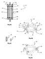
- FIGS. 2A to 2D represent a transformer coil and its various elements according to a preferred embodiment of the invention.
- the figure 3 shows the combination of three active parts to achieve a three-phase transformer module according to the invention.
- the figure 4 shows a modular transformer according to one embodiment of the invention.
- the system according to the invention can also be used in single-phase or any other mode: the skilled person will recognize the advantages of the invention and the changes to be made.
- the coils and the terminals are advantageously shielded in order to allow a saving of space during a side-by-side installation for the formation of a modular transformation bench.
- a three-phase transformer module 10 comprises a magnetic circuit associated with three active transformer parts 12, which are placed side by side and held by an upper yoke 14.
- Each active part 12 comprises, around a magnetic circuit core an internal coil, usually the "low voltage" coil provided on the upper face 16 of two LV terminals 18, that is to say a terminal 18p for the phase and a terminal 18 n for the neutral, for a connection on the LV busbars.
- the LV coil is surrounded by an HT coil 20.
- a transfer of the connection of the active transformer parts 12 is put in place, and all the terminals are located on said upper face 16 of the module 10 of to facilitate the installation, connection and possible replacement of the module 10 if it is associated in parallel in a transformation bench. It should be noted that even if the top is the most easily accessible area for a transformer whose axis is vertical, it is possible to deport the different connection points at the other end.
- the ends of the outer winding 20 are connected to a set of shielded input and output terminals 22 and 24, which are located on the end face 16 of the active part 12.
- the set of terminals 22, 24 is advantageously doubled, so that two input terminals 22 1 , 22 2 and two terminals of output 24 1 , 24 2 are available to facilitate connections to the high voltage source, to the next module 10, and the Y or D coupling for the end module of a transformation bench.
- the complexity of shaping the coating in the insulating resin 26 of the turns of the HT coil 20 is, however, such that a simple transfer of the terminals with respect to the location of the ends of the coil winding HT 20 can not be envisaged, and that the transfer of connections from their lateral outlet to a front location according to the invention causes changes in the design of the coil 20, which can not be considered as a direct transposition of the coil BT.
- the high voltage connection system is an independent element that can be secured on a coil winding: this solution simplifies the parts to be manufactured and to standardize them; a lower element can then be provided to be secured to the other end of the coil winding.
- This solution also makes it possible to manufacture the winding of turns in several elements, in particular by the superposition of identical power wafers, an example of which is described in the patent application.
- connection system or end plate, comprises an annular element 32 ( Figure 2B ) secured to the winding of turns.
- Each of the terminals 22, 24 is "right", that is to say that it is open on the upper face 34 of the wafer 30 so as to be easily connected from the outside, preferably parallel to the axis of the coil 20.
- each terminal 22, 24 is made with a connection insert 36 placed in a suitable arrangement 38 of the ring 32, which may be, depending on the desired average size, a protrusion on the upper face 34 or, as shown, a lateral protuberance of the ring 32.
- connection inserts 36 are electrically connected to means for connection to the input and output of the winding of turns to which the system 30 is intended.
- an electrical connection 40 is embedded in the resin ring 32 between each terminal 22, 24 and an orifice adapted to receive a connector to the winding.
- the connection orifice may be lateral, but it is preferable that it be integrated with a lateral protuberance 42, 44 of the ring 32, so that the connection will also be longitudinal parallel to the axis: this system makes it possible to stabilize the stack at the same time as the electrical connection while facilitating installation.
- the connection orifice of each protuberance 42, 44 does not open into the upper face 34 to isolate the system.
- connection system 30 thus comprises at least two protuberances 42, 44 opening on the face opposite to the connection face 16, that is to say the lower face, for example provided with connection inserts 36, electrically connected to terminals 22, 24 by a line 40.
- the connection inserts 36 are advantageously identical to those used for the terminals 22, 24 to rationalize the manufacture and storage; the connection protuberances 42, 44 are intended to receive a connector 46 (for example a biconica as illustrated in FIG. Figure 2C ) for electrically connecting the terminals 22, 24 to the input and output of the winding to allow the passage of current.
- an end wafer 50 illustrated in FIG. 2D figure which comprises two protuberances 52, 54 suitable for the electrical connection at least; the protuberances 52, 54 are intended to receive a connector for connecting them respectively to the coil winding to allow the passage of current, and directly to the output protrusion 44 of the upper wafer 30, for example via
- the protuberances 52, 54 are provided with the same connection inserts 36.
- the coil 20 comprises a winding of turns 60 between an inlet and an outlet, usually at each end of the winding, which open laterally on the resin ring 26, preferably each in a protrusion 62, 64 adapted to cooperate with the connection arrangements 42, 52, 54 of the end plates 30, 50.
- the protuberances 62, 64 are open at each end: an orifice, provided for example with an insert 36 similar to the previous ones in electrical connection with the end of the turns, allows a connection by the two faces of the winding 60.
- a transformer coil HT 20 thus comprises a stack of a lower wafer 50 provided with two protuberances 52, 54 and a power wafer 60 provided with a protrusion for the inlet 62 and A protrusion for the output 64.
- An electrical connector 46 inserted in a protrusion 64 of the coil 60 and in a first protrusion 52 of the lower wafer 50, connects the output of the power wafer 60 to the output 54 of the lower wafer 50.
- a connection system 30 provided with two protuberances 42, 44 and two terminals 22, 24 is put in place, an electrical connector 46 inserted into the input protrusion 42 and the protrusion 62 connecting the input of the winding 60.
- a bar 56 connects the output protrusion 44 of the connection system 30 and the second protrusion 54 of the lower wafer 50.
- protrusion system can be replaced by an equivalent. It is further preferred, as illustrated, to add on each element 30, 50, 60 one or more arrangements, for example similar protuberances 48, 58 for mechanically connecting the elements 30, 50, 60 to each other in order to stabilize the assembly, for example by an insulating mechanical connector 66 of the plug type.
- a transformer cell 12 of 160 kVA supplying a voltage LV of 230 V comprises a lower wafer 50, a power winding 60 and an upper wafer 30 of the same dimensions as the lower wafer 50.
- the power winding 60 comprises three protuberances (one being hidden in Figure 2A ) distributed at 120 °, two protuberances 62, 64 allowing access to the inlet and the outlet of the coil winding.
- the lower wafer 50 comprises three protuberances 52, 58, 58 'distributed at 120 °, at least one, and preferably all three, being electrically connected to a fourth protrusion 54 ("exit" of the turns) diametrically opposite to the one of the other three protuberances 52; the protuberances 52, 54, 58, 58 'open on the same side.
- connection system 30 also comprises three first protuberances 42, 48, 48 'to 120 ° and a second diametrically opposite protrusion 44 opening into a face of the system; one of the first protuberances 42 and the second protrusion 44 are electrically connected to two terminals 22 1 , 22 2 , 24 1 , 24 2 disposed on either side in protuberances 38 opening on the upper face 34.
- the HT coil 20 can then be assembled, by interlocking with means of connection 46 electrical or mechanical 66, and a bar 56. Preferably, this nesting is done on site, once the low voltage coil placed around the core magnetic circuit.
- the power winding 60 can be realized by the superposition of adjustable slabs, according to the invention described in the patent application. FR 07 02010 .
- Three active parts 12 according to the invention may be coupled in a star or in a triangle to form a three-phase transformer 10 illustrated in FIG. figure 3 : the terminals 22 1 , 24 1 input / output are connected in pairs by a conventional medium or high voltage flexible connection cable 70 overmolded conventional.
- the low-voltage terminals 18 are connected, in a star or in a triangle, by a set 72 of four 20 x 5 bars separated by insulators ( figure 4 ).
- modules 10 it is also possible to make modules 10 to be coupled in parallel in order to increase the power, for example four times three modules 10 of 160 kVA for a three-phase transformer 80 of 640 kVA partially illustrated in FIG. figure 4 the BT terminals 18 are connected as usual by a busbar 72 to form a module 10, and each module 10 is connected to the others in parallel by a second set of busbars 74.
- the terminals 22 1 , 24 1 d The high voltage input / output can be connected two by two by a connection connector 70 to form a transformer block, in particular by the same type of conventional overmolded high voltage flexible cable 70.
- To make the modular transformer 80 it is also necessary to make a phase connection of the external coils 20.
- connection system 30 according to the invention, only one of the modules 10, the end module 82, is coupled in a star or a triangle: in this case it is preferred to use the second terminals 22 2 , 24 2 , different from the parallel connection terminals, to facilitate connections and reduce the number of industrial references; the use of a T-system on a single terminal 22, 24 is possible.
- the same cables 70 can be used for the parallel connection and the "star / delta" connection.
Landscapes
- Engineering & Computer Science (AREA)
- Power Engineering (AREA)
- Coils Or Transformers For Communication (AREA)
Applications Claiming Priority (1)
| Application Number | Priority Date | Filing Date | Title |
|---|---|---|---|
| FR0702011A FR2914106B1 (fr) | 2007-03-20 | 2007-03-20 | Partie active de transformateur enrobe munie d'un systeme de connexion a une extremite et transformateur ht/bt modulaire la comprenant |
Publications (1)
| Publication Number | Publication Date |
|---|---|
| EP1973127A1 true EP1973127A1 (de) | 2008-09-24 |
Family
ID=38535967
Family Applications (1)
| Application Number | Title | Priority Date | Filing Date |
|---|---|---|---|
| EP08354011A Withdrawn EP1973127A1 (de) | 2007-03-20 | 2008-02-04 | Aktiver Teil eines ummantelten Transformators, der mit einem Verbindungssystem an einem Ende ausgestattet ist, und modularer HS/NS-Transformator, der ihn enthält |
Country Status (2)
| Country | Link |
|---|---|
| EP (1) | EP1973127A1 (de) |
| FR (1) | FR2914106B1 (de) |
Cited By (2)
| Publication number | Priority date | Publication date | Assignee | Title |
|---|---|---|---|---|
| EP4687160A1 (de) * | 2024-07-31 | 2026-02-04 | Hitachi Energy Ltd | Spulenanordnung, transformator und verfahren |
| WO2026027580A1 (en) | 2024-07-31 | 2026-02-05 | Hitachi Energy Ltd | Coil arrangement, transformer and method |
Citations (8)
| Publication number | Priority date | Publication date | Assignee | Title |
|---|---|---|---|---|
| US2998583A (en) | 1956-02-13 | 1961-08-29 | Willis G Worcester | Electrical apparatus and electromagnetic coils and method of making the same |
| US3004230A (en) * | 1956-10-12 | 1961-10-10 | American Mach & Foundry | Electric inductor devices |
| US3068435A (en) * | 1954-04-19 | 1962-12-11 | Sylvania Electric Prod | Electromagnetic coils |
| US3496420A (en) * | 1968-01-18 | 1970-02-17 | Westinghouse Electric Corp | Unitary electrical power supply for individual power customers |
| US3611226A (en) * | 1969-12-08 | 1971-10-05 | Westinghouse Electric Corp | Encapsulated electrical windings |
| US3750071A (en) * | 1972-05-05 | 1973-07-31 | Westinghouse Electric Corp | Stress relieving member for encapsulated transformer windings |
| WO1998010447A1 (fr) | 1996-09-04 | 1998-03-12 | E.I. Du Pont De Nemours And Company | Transformateur haute tension/basse tension a isolation seche thermoplastique |
| WO2000025327A1 (en) * | 1998-10-26 | 2000-05-04 | A.T.T. Advanced Transformer Technologies (1998) Ltd. | A three-phase transformer |
-
2007
- 2007-03-20 FR FR0702011A patent/FR2914106B1/fr active Active
-
2008
- 2008-02-04 EP EP08354011A patent/EP1973127A1/de not_active Withdrawn
Patent Citations (8)
| Publication number | Priority date | Publication date | Assignee | Title |
|---|---|---|---|---|
| US3068435A (en) * | 1954-04-19 | 1962-12-11 | Sylvania Electric Prod | Electromagnetic coils |
| US2998583A (en) | 1956-02-13 | 1961-08-29 | Willis G Worcester | Electrical apparatus and electromagnetic coils and method of making the same |
| US3004230A (en) * | 1956-10-12 | 1961-10-10 | American Mach & Foundry | Electric inductor devices |
| US3496420A (en) * | 1968-01-18 | 1970-02-17 | Westinghouse Electric Corp | Unitary electrical power supply for individual power customers |
| US3611226A (en) * | 1969-12-08 | 1971-10-05 | Westinghouse Electric Corp | Encapsulated electrical windings |
| US3750071A (en) * | 1972-05-05 | 1973-07-31 | Westinghouse Electric Corp | Stress relieving member for encapsulated transformer windings |
| WO1998010447A1 (fr) | 1996-09-04 | 1998-03-12 | E.I. Du Pont De Nemours And Company | Transformateur haute tension/basse tension a isolation seche thermoplastique |
| WO2000025327A1 (en) * | 1998-10-26 | 2000-05-04 | A.T.T. Advanced Transformer Technologies (1998) Ltd. | A three-phase transformer |
Cited By (2)
| Publication number | Priority date | Publication date | Assignee | Title |
|---|---|---|---|---|
| EP4687160A1 (de) * | 2024-07-31 | 2026-02-04 | Hitachi Energy Ltd | Spulenanordnung, transformator und verfahren |
| WO2026027580A1 (en) | 2024-07-31 | 2026-02-05 | Hitachi Energy Ltd | Coil arrangement, transformer and method |
Also Published As
| Publication number | Publication date |
|---|---|
| FR2914106B1 (fr) | 2009-04-24 |
| FR2914106A1 (fr) | 2008-09-26 |
Similar Documents
| Publication | Publication Date | Title |
|---|---|---|
| WO2010061063A1 (fr) | Systeme d'assemblage de modules d'energie electrique | |
| US9806445B2 (en) | Method and apparatus for interconnecting distributed power sources | |
| US20200287364A1 (en) | 7-Way Crab Joint | |
| CN108780872A (zh) | 电池和用于制造电池的方法 | |
| US8699209B2 (en) | Externally fused enclosure for a solar power system | |
| EP3108725B1 (de) | Leistungsverteilerkasten mit einer eingangsleistungssammelschiene | |
| US11693031B2 (en) | Electric meter collar adaptor to divert power to distributed power generation resources | |
| JP6350219B2 (ja) | ガス絶縁スイッチギヤ | |
| EP1973127A1 (de) | Aktiver Teil eines ummantelten Transformators, der mit einem Verbindungssystem an einem Ende ausgestattet ist, und modularer HS/NS-Transformator, der ihn enthält | |
| EP1329008B2 (de) | Hybrid-hochspannungsstation mit gegenüberliegenden abgangen, und gekapselten schalt- undtrennmodulen dafür | |
| CN106298195A (zh) | 磁性元件 | |
| EP2984663B1 (de) | Transformator mit vorrichtung zur einstellung des inload-transformationsverhältnisses | |
| EP1973126B1 (de) | Spule für Oberspannung, die für einen Trockentransformator und einen Hochspannungs-/Niedrigspannungstransformator, die sie enthalten, angepasst werden kann | |
| KR20210042386A (ko) | 다상 개폐 장치 | |
| US20120312354A1 (en) | Solar module and photovoltaic array | |
| US11688552B2 (en) | Method for assembling a magnetic inductor and magnetic inductor able to be obtained by means of such a method | |
| US12028001B2 (en) | Flexible voltage transformation system | |
| US8608496B2 (en) | Connector for multi-phase conductors | |
| EP2192663A1 (de) | Hochspannung metallgekapselte elektrische schaltanlage | |
| WO2015090502A1 (en) | A modular subsea power distribution system | |
| EP0561727B1 (de) | Schalttafel für Niederspannungsdrehstromszähler | |
| OA21512A (fr) | Mini sous-station permettant de convertir la haute tension des lignes de transport directement en une tension intermédiaire ou en une basse tension. | |
| CN121816632A (zh) | 用于从源电网向客户站点提供电力的配电变压器和系统 | |
| EP3790028A1 (de) | Transformator mit mehreren sekundärspulen | |
| WO2021259624A1 (fr) | Convertisseur de tension dc/dc comprenant un module superieur et un module inferieur |
Legal Events
| Date | Code | Title | Description |
|---|---|---|---|
| PUAI | Public reference made under article 153(3) epc to a published international application that has entered the european phase |
Free format text: ORIGINAL CODE: 0009012 |
|
| AK | Designated contracting states |
Kind code of ref document: A1 Designated state(s): AT BE BG CH CY CZ DE DK EE ES FI FR GB GR HR HU IE IS IT LI LT LU LV MC MT NL NO PL PT RO SE SI SK TR |
|
| AX | Request for extension of the european patent |
Extension state: AL BA MK RS |
|
| 17P | Request for examination filed |
Effective date: 20081009 |
|
| RAP1 | Party data changed (applicant data changed or rights of an application transferred) |
Owner name: SCHNEIDER ELECTRIC INDUSTRIES SAS |
|
| AKX | Designation fees paid |
Designated state(s): AT BE BG CH CY CZ DE DK EE ES FI FR GB GR HR HU IE IS IT LI LT LU LV MC MT NL NO PL PT RO SE SI SK TR |
|
| 17Q | First examination report despatched |
Effective date: 20111019 |
|
| GRAP | Despatch of communication of intention to grant a patent |
Free format text: ORIGINAL CODE: EPIDOSNIGR1 |
|
| INTG | Intention to grant announced |
Effective date: 20130619 |
|
| STAA | Information on the status of an ep patent application or granted ep patent |
Free format text: STATUS: THE APPLICATION IS DEEMED TO BE WITHDRAWN |
|
| 18D | Application deemed to be withdrawn |
Effective date: 20131030 |