EP1973176A2 - Procédé et dispositif destinés à la fabrication d'un module d'actionneur piézoélectrique doté d'un actionneur piézoélectrique enrobé et un module d'actionneur piézoélectrique - Google Patents
Procédé et dispositif destinés à la fabrication d'un module d'actionneur piézoélectrique doté d'un actionneur piézoélectrique enrobé et un module d'actionneur piézoélectrique Download PDFInfo
- Publication number
- EP1973176A2 EP1973176A2 EP08101460A EP08101460A EP1973176A2 EP 1973176 A2 EP1973176 A2 EP 1973176A2 EP 08101460 A EP08101460 A EP 08101460A EP 08101460 A EP08101460 A EP 08101460A EP 1973176 A2 EP1973176 A2 EP 1973176A2
- Authority
- EP
- European Patent Office
- Prior art keywords
- actuator
- piezoelectric
- sheath
- piezoelectric actuator
- metal parts
- Prior art date
- Legal status (The legal status is an assumption and is not a legal conclusion. Google has not performed a legal analysis and makes no representation as to the accuracy of the status listed.)
- Withdrawn
Links
Images



Classifications
-
- B—PERFORMING OPERATIONS; TRANSPORTING
- B21—MECHANICAL METAL-WORKING WITHOUT ESSENTIALLY REMOVING MATERIAL; PUNCHING METAL
- B21D—WORKING OR PROCESSING OF SHEET METAL OR METAL TUBES, RODS OR PROFILES WITHOUT ESSENTIALLY REMOVING MATERIAL; PUNCHING METAL
- B21D26/00—Shaping without cutting otherwise than using rigid devices or tools or yieldable or resilient pads, i.e. applying fluid pressure or magnetic forces
- B21D26/14—Shaping without cutting otherwise than using rigid devices or tools or yieldable or resilient pads, i.e. applying fluid pressure or magnetic forces applying magnetic forces
-
- H—ELECTRICITY
- H10—SEMICONDUCTOR DEVICES; ELECTRIC SOLID-STATE DEVICES NOT OTHERWISE PROVIDED FOR
- H10N—ELECTRIC SOLID-STATE DEVICES NOT OTHERWISE PROVIDED FOR
- H10N30/00—Piezoelectric or electrostrictive devices
- H10N30/01—Manufacture or treatment
- H10N30/02—Forming enclosures or casings
-
- H—ELECTRICITY
- H10—SEMICONDUCTOR DEVICES; ELECTRIC SOLID-STATE DEVICES NOT OTHERWISE PROVIDED FOR
- H10N—ELECTRIC SOLID-STATE DEVICES NOT OTHERWISE PROVIDED FOR
- H10N30/00—Piezoelectric or electrostrictive devices
- H10N30/80—Constructional details
- H10N30/88—Mounts; Supports; Enclosures; Casings
- H10N30/883—Additional insulation means preventing electrical, physical or chemical damage, e.g. protective coatings
-
- F—MECHANICAL ENGINEERING; LIGHTING; HEATING; WEAPONS; BLASTING
- F02—COMBUSTION ENGINES; HOT-GAS OR COMBUSTION-PRODUCT ENGINE PLANTS
- F02M—SUPPLYING COMBUSTION ENGINES IN GENERAL WITH COMBUSTIBLE MIXTURES OR CONSTITUENTS THEREOF
- F02M51/00—Fuel-injection apparatus characterised by being operated electrically
- F02M51/06—Injectors peculiar thereto with means directly operating the valve needle
- F02M51/0603—Injectors peculiar thereto with means directly operating the valve needle using piezoelectric or magnetostrictive operating means
Definitions
- the invention relates to a method and an apparatus for producing a piezoelectric actuator with an envelope having a piezoelectric actuator or a series of piezoelectric actuators, according to the preamble of claims 1 and 4 and a piezoelectric actuator produced in this way, for example, in a piezo injector for timely and precise dosage of fuel in an internal combustion engine can be used according to claim 5.
- Such a piezo injector consists essentially of a holding body and arranged in the holding body piezoelectric actuator, which has arranged between an actuator head and an actuator base, stacked piezoelectric elements, each consisting of enclosed with internal electrodes piezoelectric layers.
- the piezoelectric elements are constructed using a material with a suitable crystal structure (piezoceramic) for the piezoelectric layers so that upon application of an external voltage to the internal electrodes, a mechanical reaction of the piezoelectric elements takes place, which in dependence on the crystal structure and the contact areas of the electrical voltage, a pressure or train in a predeterminable direction.
- the piezoelectric actuator is connected to a nozzle injector with a nozzle needle, so that a nozzle opening is released by applying a voltage to the piezoelectric elements.
- These common rail injectors can be constructed so that an indirectly controlled by the piezoelectric actuator nozzle needle is present, wherein the piezoelectric actuator is directly or indirectly surrounded by the pressure of the fuel and between the nozzle needle and the piezoelectric actuator only a hydraulic coupling space is provided. If the piezoelectric actuators are in the low pressure range of the fuel (about 60 bar), as is the case with indirectly controlled needle movements, then a metal sleeve seal of the piezoelectric actuator can be realized with a membrane as lifting and / or temperature-compensating element.
- the piezo actuators are operated directly in the diesel fuel under high pressure (about 2000 bar), the aforementioned relatively rigid sleeve / membrane seal the high system pressures and higher strokes of the piezoelectric actuator among the available Space conditions would not withstand.
- the piezoelectric actuator For example, with regard to their electrical insulation, it is therefore also known to envelop the piezoelectric actuator with an elastomer. Since the presence of fuel, in particular with regard to its conductive constituents, would lead to an electrical flashover between the electrodes and thus the failure of the piezoactuator on the surface of the piezoactuator, the piezoactuator must also be connected to the seam by direct sealing contact with the fuel - or joints are protected.
- a piezo injector is known with an actuator module acting on a valve member via a hydraulic pressure booster, in which the piezo elements of the piezoelectric actuator are arranged in an envelope provided with a metallic corrugated bellows.
- the invention is based on a piezoelectric actuator described above with a piezoelectric actuator, which is clamped between a metallic actuator head and a metallic actuator base and provided with a sheath which is attached to the actuator head, the actuator base and / or the piezoelectric actuator.
- the sealing attachment of the casing is advantageously carried out by an external application of a metal part enclosing the casing and an attachment by pressing the metal part to the casing by means of an electromagnetic forming process.
- the electromagnetic forming process is in itself, for example, from DE 20 2004 014 6582 U1 known in which is described how the electromagnetic forming derat made at electrically and / or magnetically conductive workpieces can be that a material deformation can be carried out in a required form and direction for each application.
- the method can be advantageously used in the production of a piezoelectric actuator, in which the piezoelectric actuator is part of a piezo injector for an injection system for fuel in an internal combustion engine and the fuel flows around the envelope.
- the piezoelectric actuator module, the envelope and the metal parts can have a round, oval, quadrangular or polygonal contour.
- the piezoelectric actuator is used for example in the high pressure region of the fuel of at least 2000 bar pulsating with a temperature load in the range of about -40 to + 180 ° C and can with the invention from moisture (H 2 O) diesel, RME or other electrically conductive substances and also be permanently protected from particles and suspended matter.
- the sheaths of the piezoelectric actuator can be flexible plastic or metal sleeves, which are shrunk or otherwise adapted to the contour of the piezoelectric actuator or the actuator head and the actuator base, for example.
- the metal parts as joining partners can have different shapes, with which they ensure a tight closure of the enclosure by being pressed over the envelope of the piezoelectric actuator to the contour of the actuator head and / or the Aktorfußes and thereby, for example, in depressions of the other joining partner directly or indirectly intervention.
- the metal parts may protrude beyond the enclosure to form a mechanical stop, or the metal parts may have a cutting edge protruding over the enclosure to form a mechanical stop, or the enclosure, the actuator head and / or the actuator foot may have a cutting edge into which outstanding metal parts are einpressbar.
- the method is carried out so that a pulsating high energy, for example in the range of about 5 to 25 kJ, depending on the material used, and with a pulse frequency in the range of about 6kHz in the region of the metal part as a joining partner and / or the envelope , the actuator base, the actuator head and / or the piezoelectric actuator is produced as a different joining partner by a coil.
- the necessary pulsating high current in the coil is generated in a simple manner by means of a pulse generator, which consists of a capacitor and a series-connected high-current switch and thus applied to the coil in the vicinity of the joining partners such that material movement and / or deformation at least one the joining partner takes place.
- Embodiments are also proposed in which the metal parts which can be molded or pressed on by the electromagnetic forming process are provided with biting edges which are provided on the casing of the piezoactuator and / or on the actuator base and / or bear against the actuator head, wherein the metal parts may rest laterally directly adjacent to the enclosure or with a lateral distance.
- the invention may, as already mentioned, both with a fixed position of the metal parts relative to the Anbinde hope (actuator base, actuator head), or on both sides caused by the production-related length of the enclosure free positions within a distance.
- metal parts and the actuator base and / or the actuator head and additional metal rings lie and the metal parts may have different contours as curvatures, corrugations, waves, grooves or barbs on the support area on the envelope.
- connection according to the invention of the enclosure or the protective composite to the Anbinde so is particularly advantageous if a length compensation of manufacturing tolerances while preserving the connection tightness is to be achieved primarily with metal as a sheath.
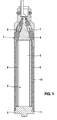
- a piezoelectric actuator module 1 is shown with at least one piezoelectric actuator 2, which can be used, for example, for Nadelhub Kunststoffung in the injection system for fuel in an internal combustion engine.
- Piezo elements 3 are part of the piezoelectric actuator 2, which still has an actuator base 4 and an actuator head 5, for example made of steel.
- a mechanical arrangement located vertically below the actuator head 5 can be actuated in such a way that a release of a nozzle opening of the injection system can take place here.
- the piezoelectric actuator module 1 with the piezoelectric actuator 2 is according to FIG. 2 round, oval, square or polygonal executed and installed in an injector body, not shown here, wherein the fuel is passed through the interior of the injector body on the assembly 1. This fuel can then be injected for example in a so-called common rail system under the rail pressure mentioned in the introduction or another predetermined pressure in the combustion chamber of an internal combustion engine, not shown here.
- a sheath 10 is provided, which in particular firmly surrounds the sensitive piezoelectric elements 3 and is also connected to the actuator head 5 via a Verkrallung or compression 11 during assembly.
- FIGS. 3a to 3e various metal parts shown with the method explained below of the electromagnetic deformation according to the force arrows F on an inventive cover 20 or coating and thus on the actuator head 5 or actuator foot 4 (see FIG. FIG. 1 ) should be pressed.
- a metal part 21 is shown protruding with a part 22 over the casing 20; in the FIG. 3b an embodiment is shown in which a Vitonring 23 is joined between the enclosure and the piezoelectric actuator, not shown here.
- the metal part 21 has a cutting edge 24 and that in the embodiment according to FIG 3d figure the sheath 20 and an actuator head or actuator base 25 also have a cutting edge 26, via which a stop for the tight fit of the metal part 21 can also be reached.
- the metal part 21 ' encloses the envelope 20 axially and radially.
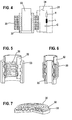
- FIG. 4 3 shows schematically how a coil 30 is used to carry out the method known per se from the prior art in such a way that a pulsating high current is generated by a pulse generator 31 and fed into the coil 30 and that the coil 30 is in the region of the metal part 32 is arranged as a joining partner and / or in the area of another joining partner 33.
- the pulsating high current is generated in a simple manner by means of the pulse generator 31 such that after a start signal with a high-current switch 34, the capacitance C flows this current via the inner inductance L, the inner resistor R and the coil 30.
- the metal part 32 experiences a radial acceleration, with which the metal part 32 is pressed onto the joining partner 33.
- the capacity is recharged at small intervals (for example 75-150 s) and the process repeats.
- small intervals for example 75-150 s
- protective plates In order to avoid the electromagnetic influence on the piezoelectric actuator, it is also possible here to provide protective plates.
- FIG. 5 shows an embodiment with the joining partners 32 and 33, in which the coil 30 acts by the application in the interior of the arrangement as an expansion coil and in FIG. 6 an embodiment of joining partners 32 and 33 is shown in which the coil 30 acts externally as a compression coil.
- FIG. 7 It is also possible that the joining partners are 32 and 33 slices and the coil 30 is thus designed as overlying flat coil.
- FIG. 8 shows an embodiment of a piezoelectric actuator 40 or a series of such piezoelectric actuators connected to one another with an actuator base 41 and an actuator head 42 as attachment parts.
- a sheath 43 is placed as a protective composite, which consists essentially of an electrically insulating filling material and an outer mechanically reinforcing sheath.
- metal parts 44 are tightly mounted as rings by means of a previously described electromagnetic deformation, which have B Schokanten 45 which are fixedly attached to the actuator base 41 and the actuator head 42.
- FIG. 9 an embodiment can be seen, in which, in a modification to the FIG. 8 the metal parts 44 formed or shrunk on by the magnetic deformation are additionally provided with biting edges 46, which act on the envelope 43.
- FIG. 10 and FIG. 11 each embodiments are shown in which the formed by magnet forming or shrunk metal parts 44 on one side with a Distance in the longitudinal direction ( FIG. 10 left) and directly on the other side ( FIG. 10 right) or directly on both ( FIG. 11 ).
- FIGS. 12 and 13 each show an embodiment with integrally formed by magnet forming or shrunk metal rings 44, which have an additional metal ring 47 on which rest with the B disclosekanten 45 provided metal parts 44 on the actuator base 41 and the actuator head 42.
- the metal part 41 in each case before the magnetic forming looks (left side) and then rests on the additional metal ring 47 after the magnet forming (right side).
- the additional metal rings may also be a solid structural part of the actuator base 41 or the actuator head 42.
- FIGS. 14a to 14f variants of the metal part 44 can be seen in section, which have different contours of the contact area of the metal part 44 on the envelope 43 of the piezoelectric actuator 40.
- the Figure 14a shows a smooth contour that FIG. 14b shows a contour with a curvature 48, the FIG. 14c shows a contour with two vaults 48, the Figures 14d and 14e show contours with different corrugations or grooves 49 and the FIG. 14f shows a contour with a barb 50.
Landscapes
- Engineering & Computer Science (AREA)
- Physics & Mathematics (AREA)
- Fluid Mechanics (AREA)
- Mechanical Engineering (AREA)
- Manufacturing & Machinery (AREA)
- Fuel-Injection Apparatus (AREA)
- General Electrical Machinery Utilizing Piezoelectricity, Electrostriction Or Magnetostriction (AREA)
Applications Claiming Priority (2)
| Application Number | Priority Date | Filing Date | Title |
|---|---|---|---|
| DE102007012922 | 2007-03-19 | ||
| DE102007042216A DE102007042216A1 (de) | 2007-03-19 | 2007-09-05 | Verfahren und Vorrichtung zur Herstellung eines Piezoaktormoduls mit einem umhüllten Piezoaktor und ein Piezoaktormodul |
Publications (2)
| Publication Number | Publication Date |
|---|---|
| EP1973176A2 true EP1973176A2 (fr) | 2008-09-24 |
| EP1973176A3 EP1973176A3 (fr) | 2012-05-02 |
Family
ID=39535214
Family Applications (1)
| Application Number | Title | Priority Date | Filing Date |
|---|---|---|---|
| EP08101460A Withdrawn EP1973176A3 (fr) | 2007-03-19 | 2008-02-11 | Procédé et dispositif destinés à la fabrication d'un module d'actionneur piézoélectrique doté d'un actionneur piézoélectrique enrobé et un module d'actionneur piézoélectrique |
Country Status (2)
| Country | Link |
|---|---|
| EP (1) | EP1973176A3 (fr) |
| DE (1) | DE102007042216A1 (fr) |
Cited By (2)
| Publication number | Priority date | Publication date | Assignee | Title |
|---|---|---|---|---|
| EP2034531A3 (fr) * | 2007-09-06 | 2012-09-05 | Robert Bosch GmbH | Module piézoactionneur doté d'un système de couche de protection et son procédé de fabrication |
| EP2818686A1 (fr) * | 2013-06-26 | 2014-12-31 | Robert Bosch Gmbh | Actionneur piézoélectrique et procédé de fabrication d'un actionneur piézoélectrique |
Citations (2)
| Publication number | Priority date | Publication date | Assignee | Title |
|---|---|---|---|---|
| WO2001048834A2 (fr) | 1999-12-23 | 2001-07-05 | Siemens Aktiengesellschaft | Element piezo-electrique |
| DE10139871A1 (de) | 2001-08-14 | 2003-02-27 | Bosch Gmbh Robert | Ventil zum Steuern von Flüssigkeiten |
Family Cites Families (3)
| Publication number | Priority date | Publication date | Assignee | Title |
|---|---|---|---|---|
| US3222771A (en) * | 1964-10-21 | 1965-12-14 | Robert J Schwinghamer | Method of securing objects together by magnetic deformation |
| WO2006101914A1 (fr) * | 2005-03-18 | 2006-09-28 | Cooper-Standard Automotive, Inc. | Sertissage de formage electromagnetique |
| DE102005024710A1 (de) * | 2005-05-30 | 2006-12-07 | Robert Bosch Gmbh | Brennstoffeinspritzventil |
-
2007
- 2007-09-05 DE DE102007042216A patent/DE102007042216A1/de not_active Withdrawn
-
2008
- 2008-02-11 EP EP08101460A patent/EP1973176A3/fr not_active Withdrawn
Patent Citations (2)
| Publication number | Priority date | Publication date | Assignee | Title |
|---|---|---|---|---|
| WO2001048834A2 (fr) | 1999-12-23 | 2001-07-05 | Siemens Aktiengesellschaft | Element piezo-electrique |
| DE10139871A1 (de) | 2001-08-14 | 2003-02-27 | Bosch Gmbh Robert | Ventil zum Steuern von Flüssigkeiten |
Cited By (2)
| Publication number | Priority date | Publication date | Assignee | Title |
|---|---|---|---|---|
| EP2034531A3 (fr) * | 2007-09-06 | 2012-09-05 | Robert Bosch GmbH | Module piézoactionneur doté d'un système de couche de protection et son procédé de fabrication |
| EP2818686A1 (fr) * | 2013-06-26 | 2014-12-31 | Robert Bosch Gmbh | Actionneur piézoélectrique et procédé de fabrication d'un actionneur piézoélectrique |
Also Published As
| Publication number | Publication date |
|---|---|
| DE102007042216A1 (de) | 2008-09-25 |
| EP1973176A3 (fr) | 2012-05-02 |
Similar Documents
| Publication | Publication Date | Title |
|---|---|---|
| EP1906464B1 (fr) | Actuateur piézo-éléctrique doté d'une gaine, destiné à l'insertion dans un piézo-injecteur | |
| EP1901360B1 (fr) | Module de piezoactionneur doté d'un piezoactionneur gainé | |
| EP1973176A2 (fr) | Procédé et dispositif destinés à la fabrication d'un module d'actionneur piézoélectrique doté d'un actionneur piézoélectrique enrobé et un module d'actionneur piézoélectrique | |
| DE102006026152A1 (de) | Anordnung mit einem beschichteten Piezoaktor | |
| EP2058873B1 (fr) | Piézoactionneur et module de piézoactionneur doté d'un système de couche de protection | |
| EP2013922B1 (fr) | Module d'actionneur piézoélectrique avec gaine et son procédé de fabrication | |
| EP1919005B1 (fr) | Agencement d'un actionneur piézo dans une enveloppe d'un module d'actionneur piézo | |
| EP2031669B1 (fr) | Module d'actionneur piézoélectrique comprenant une enveloppe du piézoactionneur et son procédé de fabrication | |
| EP1936708A2 (fr) | Module actionneur doté d'un piézoactionneur gainé et procédé de fabrication de celui-ci | |
| EP1929554B1 (fr) | Ensemble comportant un actionneur piezoelectrique et procede de fabrication dudit ensemble | |
| WO2012069235A1 (fr) | Module d'actionneur piézoélectrique et soupape d'injection de carburant | |
| EP2011169B1 (fr) | Piézoactionneur doté d'électrodes internes, à contact externe, d'un élément piézoélectrique | |
| EP1909339B1 (fr) | Module d'actionneur ayant un piezoactionneur gainé | |
| DE102005016461A1 (de) | Brennstoffeinspritzventil | |
| DE102008004227A1 (de) | Piezoaktormodul mit mehreren Piezoaktoren und ein Verfahren zu dessen Herstellung | |
| EP2034532A1 (fr) | Module d'actionneur piézoélectrique comprenant un système de couche de protection et son procédé de fabrication | |
| DE102005039558B4 (de) | Anordnung mit einem Piezoaktor und ein Verfahren zu dessen Herstellung | |
| EP1929620A1 (fr) | Ensemble comportant un actionneur piezoelectrique et procede de fabrication dudit ensemble | |
| EP1920477A1 (fr) | Ensemble comprenant un actionneur piezoelectrique | |
| EP1758237A1 (fr) | Dispositif comprenant un actionneur piézoélectrique et un procédé de sa fabrication | |
| DE102014215327A1 (de) | Piezoaktor für einen Kraftstoffinjektor und Kraftstoffinjektor | |
| EP1909338A2 (fr) | Dispositif piézoactionneur avec une couche d'isolation | |
| DE102015212993A1 (de) | Piezoaktormodul und Verfahren zu dessen Herstellung | |
| WO2007023034A2 (fr) | Dispositif comprenant un actionneur piezo-electrique et procede pour le produire | |
| DE102015213003A1 (de) | Piezoaktormodul und Piezoinjektor |
Legal Events
| Date | Code | Title | Description |
|---|---|---|---|
| PUAI | Public reference made under article 153(3) epc to a published international application that has entered the european phase |
Free format text: ORIGINAL CODE: 0009012 |
|
| AK | Designated contracting states |
Kind code of ref document: A2 Designated state(s): AT BE BG CH CY CZ DE DK EE ES FI FR GB GR HR HU IE IS IT LI LT LU LV MC MT NL NO PL PT RO SE SI SK TR |
|
| AX | Request for extension of the european patent |
Extension state: AL BA MK RS |
|
| PUAL | Search report despatched |
Free format text: ORIGINAL CODE: 0009013 |
|
| AK | Designated contracting states |
Kind code of ref document: A3 Designated state(s): AT BE BG CH CY CZ DE DK EE ES FI FR GB GR HR HU IE IS IT LI LT LU LV MC MT NL NO PL PT RO SE SI SK TR |
|
| AX | Request for extension of the european patent |
Extension state: AL BA MK RS |
|
| RIC1 | Information provided on ipc code assigned before grant |
Ipc: B21D 26/14 20060101ALI20120329BHEP Ipc: H01L 41/22 20060101ALI20120329BHEP Ipc: H01L 41/053 20060101AFI20120329BHEP |
|
| AKY | No designation fees paid | ||
| REG | Reference to a national code |
Ref country code: DE Ref legal event code: R108 |
|
| REG | Reference to a national code |
Ref country code: DE Ref legal event code: R108 Effective date: 20130109 |
|
| STAA | Information on the status of an ep patent application or granted ep patent |
Free format text: STATUS: THE APPLICATION IS DEEMED TO BE WITHDRAWN |
|
| 18D | Application deemed to be withdrawn |
Effective date: 20121103 |