EP1973181B1 - Mecanisme de verrouillage de batterie independante - Google Patents
Mecanisme de verrouillage de batterie independante Download PDFInfo
- Publication number
- EP1973181B1 EP1973181B1 EP07706601.7A EP07706601A EP1973181B1 EP 1973181 B1 EP1973181 B1 EP 1973181B1 EP 07706601 A EP07706601 A EP 07706601A EP 1973181 B1 EP1973181 B1 EP 1973181B1
- Authority
- EP
- European Patent Office
- Prior art keywords
- battery pack
- hook
- mounting part
- operation parts
- case
- Prior art date
- Legal status (The legal status is an assumption and is not a legal conclusion. Google has not performed a legal analysis and makes no representation as to the accuracy of the status listed.)
- Active
Links
Images


Classifications
-
- B—PERFORMING OPERATIONS; TRANSPORTING
- B25—HAND TOOLS; PORTABLE POWER-DRIVEN TOOLS; MANIPULATORS
- B25F—COMBINATION OR MULTI-PURPOSE TOOLS NOT OTHERWISE PROVIDED FOR; DETAILS OR COMPONENTS OF PORTABLE POWER-DRIVEN TOOLS NOT PARTICULARLY RELATED TO THE OPERATIONS PERFORMED AND NOT OTHERWISE PROVIDED FOR
- B25F5/00—Details or components of portable power-driven tools not particularly related to the operations performed and not otherwise provided for
- B25F5/02—Construction of casings, bodies or handles
-
- H—ELECTRICITY
- H01—ELECTRIC ELEMENTS
- H01M—PROCESSES OR MEANS, e.g. BATTERIES, FOR THE DIRECT CONVERSION OF CHEMICAL ENERGY INTO ELECTRICAL ENERGY
- H01M50/00—Constructional details or processes of manufacture of the non-active parts of electrochemical cells other than fuel cells, e.g. hybrid cells
- H01M50/20—Mountings; Secondary casings or frames; Racks, modules or packs; Suspension devices; Shock absorbers; Transport or carrying devices; Holders
- H01M50/202—Casings or frames around the primary casing of a single cell or a single battery
-
- H—ELECTRICITY
- H01—ELECTRIC ELEMENTS
- H01M—PROCESSES OR MEANS, e.g. BATTERIES, FOR THE DIRECT CONVERSION OF CHEMICAL ENERGY INTO ELECTRICAL ENERGY
- H01M50/00—Constructional details or processes of manufacture of the non-active parts of electrochemical cells other than fuel cells, e.g. hybrid cells
- H01M50/20—Mountings; Secondary casings or frames; Racks, modules or packs; Suspension devices; Shock absorbers; Transport or carrying devices; Holders
- H01M50/204—Racks, modules or packs for multiple batteries or multiple cells
- H01M50/207—Racks, modules or packs for multiple batteries or multiple cells characterised by their shape
- H01M50/213—Racks, modules or packs for multiple batteries or multiple cells characterised by their shape adapted for cells having curved cross-section, e.g. round or elliptic
-
- H—ELECTRICITY
- H01—ELECTRIC ELEMENTS
- H01M—PROCESSES OR MEANS, e.g. BATTERIES, FOR THE DIRECT CONVERSION OF CHEMICAL ENERGY INTO ELECTRICAL ENERGY
- H01M50/00—Constructional details or processes of manufacture of the non-active parts of electrochemical cells other than fuel cells, e.g. hybrid cells
- H01M50/20—Mountings; Secondary casings or frames; Racks, modules or packs; Suspension devices; Shock absorbers; Transport or carrying devices; Holders
- H01M50/244—Secondary casings; Racks; Suspension devices; Carrying devices; Holders characterised by their mounting method
-
- H—ELECTRICITY
- H01—ELECTRIC ELEMENTS
- H01M—PROCESSES OR MEANS, e.g. BATTERIES, FOR THE DIRECT CONVERSION OF CHEMICAL ENERGY INTO ELECTRICAL ENERGY
- H01M50/00—Constructional details or processes of manufacture of the non-active parts of electrochemical cells other than fuel cells, e.g. hybrid cells
- H01M50/20—Mountings; Secondary casings or frames; Racks, modules or packs; Suspension devices; Shock absorbers; Transport or carrying devices; Holders
- H01M50/247—Mountings; Secondary casings or frames; Racks, modules or packs; Suspension devices; Shock absorbers; Transport or carrying devices; Holders specially adapted for portable devices, e.g. mobile phones, computers, hand tools or pacemakers
-
- Y—GENERAL TAGGING OF NEW TECHNOLOGICAL DEVELOPMENTS; GENERAL TAGGING OF CROSS-SECTIONAL TECHNOLOGIES SPANNING OVER SEVERAL SECTIONS OF THE IPC; TECHNICAL SUBJECTS COVERED BY FORMER USPC CROSS-REFERENCE ART COLLECTIONS [XRACs] AND DIGESTS
- Y02—TECHNOLOGIES OR APPLICATIONS FOR MITIGATION OR ADAPTATION AGAINST CLIMATE CHANGE
- Y02E—REDUCTION OF GREENHOUSE GAS [GHG] EMISSIONS, RELATED TO ENERGY GENERATION, TRANSMISSION OR DISTRIBUTION
- Y02E60/00—Enabling technologies; Technologies with a potential or indirect contribution to GHG emissions mitigation
- Y02E60/10—Energy storage using batteries
Definitions
- the present invention relates to a locking mechanism of a battery pack, as a power supply for an electric tool and so on, which is attachable to and detachable from an object equipment such as the electric tool and a battery charger.
- the battery pack of this type is attachable to and detachable from a grip part of an electric tool or a battery charger, and is so constructed that when the battery pack has been attached, positive and negative terminals of the battery pack are brought into contact with terminals provided on the object equipment such as the electric tool, the battery charger, and so on.
- JP-A-2001-229895 there has been known a conventional attaching structure of the battery pack which is so constructed that a hook is provided in a rear part of the battery pack, and locking means to be locked to and unlocked from a receiving part of the electric tool is linked to the hook.
- Attaching of the battery pack is performed by sliding the battery pack forward toward a determined position of the object equipment to push it in, and by locking the locking means to the receiving part of the object equipment.
- detaching of the battery pack can be performed by pushing the hook on the back face downward with fingers to release the locked state of the locking means, and thereafter, by withdrawing the battery pack backward.
- JP-A-2004-039638 there has been known another conventional attaching structure of a battery pack which is so constructed that a pair of operation parts are provided at both sides of the battery pack, and detaching of the battery pack can be performed by pressing the operation parts with a thumb and an index finger of a single hand so as to clamp them from below thereby to release the lock between the battery pack and the object equipment such as the electric tool.
- JP 2001155700 A discloses a battery pack having a hook that is arranged into a rear surface of the battery pack, a slope which is arranged into its top portion, and coupling bodies are inserted into its bottom portion.
- a bottom surface is continuously arranged into the bottom portion in horizontal, and a coil spring is between a bottom plate and a bottom case.
- the operation part of the battery pack is a single member.
- One or more embodiments of the invention provide a locking mechanism of a battery pack which can be easily handled, and can reliably attach and detach the battery pack to and from an object equipment such as an electric tool and a battery charger, and in which sufficient strength against an impact of dropping or so can be obtained.
- a locking mechanism of a battery pack provided with a hook on a case which contains a battery and is attachable to and detachable from an object equipment by sliding, the hook being lockable to amountingpart of the object equipment, and operation parts linked to the hook for releasing the lock, wherein the mounting part is provided on a bottom face of the object equipment, while the hook is provided on an upper face of the battery pack, the hook is urged to move upward by an elastic body in a direction of being locked to the mounting part, the operation parts are arranged in both side parts of the case within such a range that they can be grasped with a single hand from both sides of a backward end in a sliding direction of the case, and the operation parts are operated from both sides, whereby the lock between the hook and the mounting part is released against the urge by the elastic body.
- the hook is arranged on un upper face of the battery pack so as to move in a vertical direction
- a first slanted face is formed on the hook at a front face in the sliding direction and can be engaged with the mounting part of the object equipment
- second slanted faces are formed on both sides of the hook at positions corresponding to the operating parts, whereby when the operation parts are engaged with the second slanted faces to push the second slanted faces, the hook moves downward thereby to release the lock between the hook and the mounting part.
- the hook is locked to the object equipment and fixed, by sliding it with respect to the mounting part.
- the operation parts are arranged in both side parts of the case within such a range that they can be grasped with a single hand from both sides of a backward end in the sliding direction of the case. Therefore, when the battery pack is to be detached, the case is rigidly clamped with the single hand, which is an act of rigidly holding the case in the single hand, at the same time. In this manner, releasing the lock of the hook and rigidly grasping the case for withdrawal are the same action, and therefore, it is possible to easily and reliably withdraw the battery pack from the object equipment. Accordingly, the battery pack can be easily handled.
- the hook is arranged on the upper face of the case, there is a sufficient space for installing the large-sized hook. Accordingly, it is possible to take sufficient strength against an impact of dropping.
- the first slanted face which is formed on the front face in the sliding direction of the hook is engaged with the mounting part of the object equipment by sliding the battery pack with respect to the mounting part, and the hook moves in a vertical direction with respect to the mounting part by sliding, whereby the hook is locked to the mounting part and fixed.
- the hook is moved downward by operating the operation parts from both sides to allow the operation parts to be engaged with the second slanted faces so that the second slanted faces are pushed in, whereby the lock of the hook to the mounting part is released. Thereafter, the battery pack may be slid to be withdrawn.
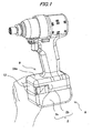
- Fig. 1 is a perspective view of a battery pack showing a state where the battery pack is attached to an electric tool
- Fig. 2 is a perspective view of the battery pack showing a state before the battery pack is attached to the electric tool
- Fig. 3 is a cut-away view showing a locking part in Fig. 1
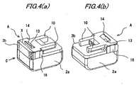
- Fig. 4(a) is a perspective view of the battery pack as seen from the front when it is attached to the electric tool
- Fig. 4(b) is a perspective view of the battery pack as seen from the back when it is attached to the electric tool
- Fig. 5 is an exploded perspective view of the battery pack
- Fig. 6 is a perspective view partially in section taken at a section X in Fig. 4(a) , as seen in a direction of an arrow mark C.
- sign A represents a battery pack
- sign B represents a mounting part which is provided in a lower part of a grip of an electric tool.
- the battery pack A is slidably attached to the mounting part B of the electric tool so as to be attached and detached.
- the battery pack A includes an outer case 2 and an inner case 3.
- the outer case 2 includes a case body 2a in a shape of a box which is open at its upper end, and a lid member 2b for closing the open end.
- the inner case 3 is so constructed as to contain and retain eight batteries.
- the inner case 3 is received inside the outer case 2, after the batteries have been contained therein.
- the lid member 2b is put on the inner case 3, and integrally coupled to the outer case 2, by inserting screws 4 into screw insertion pipes 5 inside the outer case 2 from below, to be screwed into screw receiving parts 6 which are formed at a back side of the lid member 2b.
- the lid member 2b includes a lower plate 8, guide arms 10 provided at both sides on the lower plate 8, an upper plate 11 provided in rear of the guide arms 10, a back plate 12 which is formed downward from a backward end of the upper plate 11.
- An opening 13 is formed in the upper plate 11, and openings 9 are formed in both side faces of the upper plate 11.
- a hook 14 is provided inside the opening 13 on the backward upper face.
- a locking jaw 18 adapted to be engaged with the mounting part B of the object equipment is formed in an upper end portion of the hook 14, and a first slanted face 15a adapted to be pushed down by the mounting part B of the object equipment at a time of attaching is formed on a front face of the locking jaw 18 in a sliding direction.
- Second slanted faces 15b adapted to be engaged with operation parts 16 which are arranged inside the openings 9 are formed at both sides of a lower part of the hook 14, and a spring receiving part 17 is formed below an intermediate part of the hook 14.
- the second slanted faces 15b and the screw receiving part 17 are arranged in a space 22 which is formed in front of the back plate 12.
- the second slanted faces 15b are engaged with respective one ends of the operation parts 16 and urged upward by a compression spring 21 which is provided between the spring receiving part 17 and a spring receiving part 20 formed on an upper face of the inner case 3.
- the hook 14 is urged upward.
- the operation parts 16 are pushed inward, the second slanted faces 15b are moved downward in association, which enables the entire hook 14 to move downward from the opening 13 to a position below the upper plate 11.
- the battery pack A has such a size that it can be grasped with a single hand, and the operation parts 16 at the both sides are formed within such a range that they can be grasped with a single hand from both sides of the back face.
- the mounting part B of the battery pack A is formed in a lower end part of the electric tool.
- this mounting part B includes a base 24 and side pieces 25 which are formed at both sides below the base 24.
- the side pieces 25 are provided with guide ribs 26 on inner faces of lower parts thereof, and slide grooves 27 are respectively formed between the base 24 and the guide ribs 26 so that the guide arms 10 of the battery pack A can slide in the slide grooves 27.
- a height of the guide ribs 26 is formed to such extent that the ribs 26 can be slidably engaged with grooves 23 between the lower plate 8 of the battery pack A and the guide arms 10.
- an engaging groove 28 which is adapted to be engaged with the hook 14 of the battery pack A, and a flat part 29 is formed in front and in rear of the engaging groove 28 (See Fig. 3 ).
- the guide arms 10 of the battery pack A are slid into the slide grooves 27 of the mounting part B to be pushed therein, as shown in Fig. 2 .
- the guide ribs 26 of the mounting part B are simultaneously engaged with the grooves 23.
- the battery pack A is grasped with a single hand from the back with fingers extended forward, as shown in Fig. 1 , and the operation parts 16 at the both sides are pressed inward so as to be clamped from both sides.
- the second slanted faces 15b of the hook 14 are pushed down by the operation parts 16, and the locking jaw 18 moves downward to be released from the lock to the locking groove 28 (See Figs. 3 and 6 ). Then, in this state, the battery pack A may be slid in an opposite direction thereby to be detached from the mounting part B of the electric tool.
- the operation parts 16 are arranged in both side parts of the case within such a range that they can be grasped with a single hand from both sides of a backward end in a sliding direction of the case. Therefore, when the battery pack A is detached, the case is rigidly clamped with the single hand as shown in Fig. 1 , which is an act of rigidly holding the case in the single hand, at the same time. Besides, when the operation parts 16 are pushed in, the fingers can be easily engaged with the openings 9 as shown in Fig. 5 , according to the action. In this manner, releasing the lock of the hook 14 and rigidly grasping the case for withdrawal are the same action, and therefore, it is possible to easily and reliably withdraw the battery pack A from the object equipment. Consequently, such an accident that the battery pack A may drop from the hand during attaching or detaching the battery pack A can be advantageously prevented.
- the second slanted faces 15b are integrally formed with the hook 14, and kept in contact with the operation parts 16 during attaching the battery pack A. Therefore, it is possible to smoothly perform a series of motions that the operation parts 16 are pressed inward, and that in a state where the second slanted faces 15b and the locking jaw 18 of the hook 14 have disappeared from the opening 13, the battery pack A is slid to be withdrawn from the mounting part B of the tool body. As the results, operation performance is enhanced.
- the locking jaw 18 As compared with small locking jaws which are formed on side faces of the hook at a front end thereof as in the case where the hook is formed on a side face of the battery pack A, it is possible to form the locking jaw 18 in a sufficiently large size, because the locking jaw 18 is formed at a full width of the front end of the hook 14 which is arranged on the upper plate 11 which is less restricted in view of space. Therefore, the locking jaw 18 has a large locking strength, and hence, it is possible to favorably prevent the battery pack A from being broken when it drops.
- compression spring 21 is provided as an elastic body in the above described exemplary embodiment, other material such as rubber may be employed as the elastic body, instead of the spring.
- the locking mechanism is so constructed that the operation parts are pressed inward to unlock the hook in the above described exemplary embodiment
- the operation parts may be provided with taper faces for example, and the hook may be unlocked by sliding.
- the object equipment of the invention is not limited to the electric tool, but the invention can be also applied to a battery charger for charging a battery pack, as the object equipment.
Landscapes
- Chemical & Material Sciences (AREA)
- Chemical Kinetics & Catalysis (AREA)
- Electrochemistry (AREA)
- General Chemical & Material Sciences (AREA)
- Engineering & Computer Science (AREA)
- Mechanical Engineering (AREA)
- Life Sciences & Earth Sciences (AREA)
- Biophysics (AREA)
- Computer Hardware Design (AREA)
- Battery Mounting, Suspending (AREA)
Claims (3)
- Mécanisme de verrouillage d'un bloc-batterie (A), comprenant :un crochet (14) adapté pour être prévu sur un boîtier (2) qui contient une batterie et peut être fixé et détaché d'un équipement d'objet par coulissement, le crochet (14) étant adapté pour être prévu sur une face supérieure du bloc- batterie (A) et adapté pour être verrouillé sur une partie de montage (B) prévue sur une face inférieure de l'équipement d'objet ;un corps élastique (21) adapté pour pousser le crochet (14) afin de monter dans une direction dans laquelle il est verrouillé sur la partie de montage (B) ;des parties de commande (16) pour libérer le verrou qui est relié au crochet (14), les parties de commande (16) étant adaptées pour être agencées des deux côtés d'une partie d'extrémité arrière dans une direction de coulissement du boîtier (2) et les parties de commande (16) étant adaptées pour être actionnées à partir des deux côtés, moyennant quoi le verrou entre le crochet (14) et la partie de montage (B) est adapté pour être libéré contre la poussée réalisée par le corps élastique (21).
- Mécanisme de verrouillage d'un bloc-batterie (A) selon la revendication 1,
dans lequel le crochet (14) est agencé sur la face supérieure du bloc-batterie (A) et est mobile dans une direction verticale,
dans lequel une première face inclinée (15a) est formée sur le crochet (14) au niveau d'une face avant dans la direction de coulissement du boîtier (2) et peut être mise en prise avec la partie de montage (B) de l'équipement d'objet,
dans lequel les secondes faces inclinées (15b) sont formées sur les deux côtés du crochet (14) dans des positions correspondant aux parties de commande (16), et
les parties de commande (16) sont adaptées pour être mises en prise avec les secondes faces inclinées (15b) pour pousser les secondes faces inclinées (15b), de sorte que le crochet (14) descend afin de libérer le verrou entre le crochet (14) et la partie de montage (B). - Mécanisme de verrouillage d'un bloc-batterie (A) selon la revendication 1, dans lequel les parties de commande (16) sont adaptées pour être actionnées en les saisissant avec une seule main à partir des deux côtés.
Applications Claiming Priority (2)
| Application Number | Priority Date | Filing Date | Title |
|---|---|---|---|
| JP2006004851A JP5040114B2 (ja) | 2006-01-12 | 2006-01-12 | 電池パックの係止機構及び電動工具 |
| PCT/JP2007/050254 WO2007080928A1 (fr) | 2006-01-12 | 2007-01-11 | Mecanisme de verrouillage de batterie independante |
Publications (3)
| Publication Number | Publication Date |
|---|---|
| EP1973181A1 EP1973181A1 (fr) | 2008-09-24 |
| EP1973181A4 EP1973181A4 (fr) | 2009-01-28 |
| EP1973181B1 true EP1973181B1 (fr) | 2015-08-26 |
Family
ID=38256333
Family Applications (1)
| Application Number | Title | Priority Date | Filing Date |
|---|---|---|---|
| EP07706601.7A Active EP1973181B1 (fr) | 2006-01-12 | 2007-01-11 | Mecanisme de verrouillage de batterie independante |
Country Status (7)
| Country | Link |
|---|---|
| US (1) | US7858219B2 (fr) |
| EP (1) | EP1973181B1 (fr) |
| JP (1) | JP5040114B2 (fr) |
| KR (1) | KR20080091768A (fr) |
| CN (1) | CN101375433B (fr) |
| AU (1) | AU2007205531A1 (fr) |
| WO (1) | WO2007080928A1 (fr) |
Families Citing this family (44)
| Publication number | Priority date | Publication date | Assignee | Title |
|---|---|---|---|---|
| DE102006018010A1 (de) * | 2006-04-07 | 2007-10-11 | Robert Bosch Gmbh | Akkupack |
| DE102006050816B4 (de) | 2006-10-27 | 2015-10-22 | Robert Bosch Gmbh | Elektrohandwerkzeugmaschine |
| EP2149168A1 (fr) | 2007-04-23 | 2010-02-03 | Hitachi Koki CO., LTD. | Bloc de batterie et outil électrique actionné par batterie utilisant celui-ci |
| JP5370709B2 (ja) | 2007-10-29 | 2013-12-18 | 日立工機株式会社 | 電池パック及びこれを備えた電動工具 |
| US8852776B2 (en) | 2008-02-11 | 2014-10-07 | Milwaukee Electric Tool Corporation | Battery connection for a power tool |
| JP5355999B2 (ja) * | 2008-11-25 | 2013-11-27 | 株式会社マキタ | バッテリパック |
| JP2011079510A (ja) | 2009-09-10 | 2011-04-21 | Makita Corp | 電動車 |
| JP2013522215A (ja) | 2010-03-09 | 2013-06-13 | オーエスアイ・ファーマシューティカルズ,エルエルシー | 組合わせ抗癌療法 |
| JP2012043692A (ja) * | 2010-08-20 | 2012-03-01 | Makita Corp | 工具用バッテリ |
| JP5168331B2 (ja) * | 2010-09-10 | 2013-03-21 | 株式会社Jvcケンウッド | 携帯用電子機器 |
| US20120251229A1 (en) * | 2011-04-01 | 2012-10-04 | De Poan Pneumatic Corp. | Latching mechanism for battery pack of electrical tool |
| JP5553053B2 (ja) * | 2011-04-11 | 2014-07-16 | マックス株式会社 | 電池パック、電動工具及び充電器 |
| JP6017257B2 (ja) * | 2011-10-20 | 2016-10-26 | 株式会社マキタ | 切断機 |
| JP5942431B2 (ja) * | 2012-01-06 | 2016-06-29 | マックス株式会社 | 電池パック |
| WO2013139372A1 (fr) | 2012-03-19 | 2013-09-26 | Husqvarna Ab | Adaptateur de courant pour outils électriques sans fil |
| CN108878726B (zh) | 2012-03-19 | 2022-04-22 | 胡斯华纳有限公司 | 用于背包能源的载体系统、能源以及背包能源组件 |
| CN102632486B (zh) * | 2012-04-12 | 2015-05-20 | 南京德朔实业有限公司 | 电动工具 |
| JP2014038720A (ja) * | 2012-08-10 | 2014-02-27 | Hitachi Koki Co Ltd | 電池パック |
| US9764486B2 (en) | 2013-04-04 | 2017-09-19 | Milwaukee Electric Tool Corporation | Power tool |
| US10573860B2 (en) | 2013-11-19 | 2020-02-25 | Ingersoll-Rand Company | Cordless power tool batteries |
| JP5788558B2 (ja) * | 2014-04-23 | 2015-09-30 | 株式会社マキタ | 工具用バッテリ |
| JP6058760B2 (ja) * | 2015-07-28 | 2017-01-11 | 株式会社マキタ | 工具用バッテリ |
| CN106031318B (zh) * | 2015-09-08 | 2017-09-08 | 深圳市大疆创新科技有限公司 | 移动装置及其电池模组和锁定装置 |
| DE102015122844A1 (de) * | 2015-12-27 | 2017-06-29 | Faro Technologies, Inc. | 3D-Messvorrichtung mit Batteriepack |
| JP6642794B2 (ja) * | 2016-01-07 | 2020-02-12 | マックス株式会社 | 電池パック |
| US10158105B2 (en) | 2016-03-16 | 2018-12-18 | Tti (Macao Commercial Offshore) Limited | Battery pack latch mechanism |
| JP2017193044A (ja) * | 2016-04-18 | 2017-10-26 | 株式会社Tjmデザイン | 電動工具 |
| FR3056020B1 (fr) * | 2016-09-13 | 2021-01-01 | Pellenc Sa | Dispositif a batterie electrique, pour support de batterie |
| AU2017336937A1 (en) * | 2016-09-29 | 2019-03-28 | Mtd Products Inc | Split power tool |
| DE102017129619A1 (de) * | 2017-12-12 | 2019-06-13 | Metabowerke Gmbh | Vorrichtung zur Verriegelung eines Akkupacks |
| DE202018106446U1 (de) * | 2018-01-08 | 2019-02-08 | Nanjing Chervon Industry Co., Ltd. | Elektrohandwerkzeug |
| TWM612458U (zh) | 2019-03-12 | 2021-06-01 | 美商米沃奇電子工具公司 | 動力工具 |
| USD912487S1 (en) | 2019-06-12 | 2021-03-09 | Techtronic Cordless Gp | Interface of a power tool |
| US11145929B2 (en) | 2019-08-09 | 2021-10-12 | Techtronic Cordless Gp | Battery pack |
| WO2021107827A1 (fr) * | 2019-11-25 | 2021-06-03 | Husqvarna Ab | Outil de travail portatif alimenté électriquement |
| SE543800C2 (en) * | 2019-11-25 | 2021-07-27 | Husqvarna Ab | A battery lock mechanism for a battery compartment and an electrically powered hand-held work tool comprising such a battery lock mechanism |
| JP7726790B2 (ja) | 2019-11-25 | 2025-08-20 | ハスクバーナ・アーベー | 手持ち式電動作業工具 |
| JP7373769B2 (ja) * | 2020-01-29 | 2023-11-06 | パナソニックIpマネジメント株式会社 | 電池パック、及び電動工具 |
| CN111980503A (zh) * | 2020-07-27 | 2020-11-24 | 珠海格力电器股份有限公司 | 一种电池盖结构及自动门锁 |
| US12176744B2 (en) | 2020-11-23 | 2024-12-24 | Milwaukee Electric Tool Corporation | Battery charger with movable handle |
| US12011840B2 (en) | 2021-09-22 | 2024-06-18 | Harbor Freight Tools Usa, Inc. | Rotatable tool head |
| EP4302926B1 (fr) | 2022-06-16 | 2025-08-06 | Milwaukee Electric Tool Corporation | Outil compact à percussion |
| KR102702722B1 (ko) * | 2022-06-28 | 2024-09-05 | 엘지전자 주식회사 | 청소기 |
| CN116276828B (zh) * | 2023-03-24 | 2025-10-21 | 江苏大艺科技股份有限公司 | 电动工具 |
Family Cites Families (11)
| Publication number | Priority date | Publication date | Assignee | Title |
|---|---|---|---|---|
| JPH0685320B2 (ja) | 1989-10-31 | 1994-10-26 | シャープ株式会社 | 電子機器の電池収納機構 |
| US5553675A (en) * | 1994-06-10 | 1996-09-10 | Minnesota Mining And Manufacturing Company | Orthopedic surgical device |
| JP2674537B2 (ja) | 1994-11-30 | 1997-11-12 | 日本電気株式会社 | 電子機器筐体 |
| DE19905086A1 (de) * | 1999-01-29 | 2000-08-03 | Black & Decker Inc N D Ges D S | Batteriegetriebenes, handgeführtes Elektrowerkzeug |
| DE19911362A1 (de) * | 1999-03-15 | 2000-09-21 | Hilti Ag | Batteriebetriebenes Bohrgerät |
| JP2001155700A (ja) | 1999-11-24 | 2001-06-08 | Makita Corp | バッテリーパック |
| JP2001229895A (ja) | 2000-02-10 | 2001-08-24 | Makita Corp | バッテリーパック及び電動工具 |
| JP2002260619A (ja) * | 2001-03-01 | 2002-09-13 | Hitachi Koki Co Ltd | 電池工具の電池パック取付装置 |
| DE10229980A1 (de) * | 2002-07-03 | 2004-01-15 | Hilti Ag | Batteriepackung |
| JP2004155700A (ja) * | 2002-11-06 | 2004-06-03 | Kao Corp | 脳血管障害改善剤 |
| US20050058890A1 (en) * | 2003-09-15 | 2005-03-17 | Kenneth Brazell | Removable battery pack for a portable electric power tool |
-
2006
- 2006-01-12 JP JP2006004851A patent/JP5040114B2/ja not_active Expired - Lifetime
-
2007
- 2007-01-11 US US12/160,219 patent/US7858219B2/en active Active
- 2007-01-11 CN CN2007800031192A patent/CN101375433B/zh active Active
- 2007-01-11 AU AU2007205531A patent/AU2007205531A1/en not_active Abandoned
- 2007-01-11 KR KR1020087016831A patent/KR20080091768A/ko not_active Withdrawn
- 2007-01-11 EP EP07706601.7A patent/EP1973181B1/fr active Active
- 2007-01-11 WO PCT/JP2007/050254 patent/WO2007080928A1/fr not_active Ceased
Also Published As
| Publication number | Publication date |
|---|---|
| AU2007205531A1 (en) | 2007-07-19 |
| KR20080091768A (ko) | 2008-10-14 |
| JP2007188717A (ja) | 2007-07-26 |
| WO2007080928A1 (fr) | 2007-07-19 |
| JP5040114B2 (ja) | 2012-10-03 |
| EP1973181A4 (fr) | 2009-01-28 |
| US20090011325A1 (en) | 2009-01-08 |
| US7858219B2 (en) | 2010-12-28 |
| CN101375433B (zh) | 2011-01-26 |
| CN101375433A (zh) | 2009-02-25 |
| EP1973181A1 (fr) | 2008-09-24 |
Similar Documents
| Publication | Publication Date | Title |
|---|---|---|
| EP1973181B1 (fr) | Mecanisme de verrouillage de batterie independante | |
| US9403264B2 (en) | Replaceable die for pliers, pliers having such a die, and storage fixture | |
| AU2002300724B2 (en) | Power Tool With Battery Pack Ejector | |
| EP1025962B1 (fr) | Outil à main alimenté par batterie | |
| EP3120977B1 (fr) | Mécanisme de verrouillage pour bloc-batteries | |
| EP1025961B1 (fr) | Outil à main alimenté par batterie | |
| EP1833137A2 (fr) | Adaptateur pour batterie d'outil électrique | |
| JP5858526B2 (ja) | 電動工具の電池装着用アダプタおよび電動工具 | |
| JP2011142104A (ja) | 電池パック及び電動工具 | |
| CA2532264A1 (fr) | Outil electrique avec alimentation par piles | |
| CN102341975B (zh) | 锁定解除装置、连接器装置及连接器 | |
| EP3723155B1 (fr) | Boîtier de batterie | |
| US4880713A (en) | Releasable battery pack cap and holder | |
| JP5103726B2 (ja) | 電池パック | |
| WO2008047765A1 (fr) | Mécanisme d'enclenchement pour bloc-batterie | |
| JP5387865B2 (ja) | 電池パック | |
| CN220324838U (zh) | 快速插拔式连接器 | |
| KR100511307B1 (ko) | 휴대용 단말기의 배터리 잠금장치 | |
| GB2108035A (en) | Tool for inserting a stripper into and removing it from the tool carrier mounting device of a machine tool | |
| JPH0545896U (ja) | 充電池パツクの脱着構造 | |
| KR20040060285A (ko) | 배터리팩분리장치 |
Legal Events
| Date | Code | Title | Description |
|---|---|---|---|
| PUAI | Public reference made under article 153(3) epc to a published international application that has entered the european phase |
Free format text: ORIGINAL CODE: 0009012 |
|
| 17P | Request for examination filed |
Effective date: 20080703 |
|
| AK | Designated contracting states |
Kind code of ref document: A1 Designated state(s): AT BE BG CH CY CZ DE DK EE ES FI FR GB GR HU IE IS IT LI LT LU LV MC NL PL PT RO SE SI SK TR |
|
| A4 | Supplementary search report drawn up and despatched |
Effective date: 20081230 |
|
| 17Q | First examination report despatched |
Effective date: 20090318 |
|
| DAX | Request for extension of the european patent (deleted) | ||
| GRAP | Despatch of communication of intention to grant a patent |
Free format text: ORIGINAL CODE: EPIDOSNIGR1 |
|
| INTG | Intention to grant announced |
Effective date: 20150312 |
|
| GRAS | Grant fee paid |
Free format text: ORIGINAL CODE: EPIDOSNIGR3 |
|
| GRAA | (expected) grant |
Free format text: ORIGINAL CODE: 0009210 |
|
| AK | Designated contracting states |
Kind code of ref document: B1 Designated state(s): AT BE BG CH CY CZ DE DK EE ES FI FR GB GR HU IE IS IT LI LT LU LV MC NL PL PT RO SE SI SK TR |
|
| REG | Reference to a national code |
Ref country code: GB Ref legal event code: FG4D |
|
| RIN1 | Information on inventor provided before grant (corrected) |
Inventor name: AGEHARA, KIGEN Inventor name: YAMASHITA, MICHIO, |
|
| REG | Reference to a national code |
Ref country code: CH Ref legal event code: NV Representative=s name: BOVARD AG, CH Ref country code: CH Ref legal event code: EP |
|
| REG | Reference to a national code |
Ref country code: AT Ref legal event code: REF Ref document number: 745646 Country of ref document: AT Kind code of ref document: T Effective date: 20150915 |
|
| REG | Reference to a national code |
Ref country code: IE Ref legal event code: FG4D |
|
| REG | Reference to a national code |
Ref country code: DE Ref legal event code: R096 Ref document number: 602007042767 Country of ref document: DE |
|
| REG | Reference to a national code |
Ref country code: AT Ref legal event code: MK05 Ref document number: 745646 Country of ref document: AT Kind code of ref document: T Effective date: 20150826 |
|
| REG | Reference to a national code |
Ref country code: LT Ref legal event code: MG4D |
|
| PG25 | Lapsed in a contracting state [announced via postgrant information from national office to epo] |
Ref country code: GR Free format text: LAPSE BECAUSE OF FAILURE TO SUBMIT A TRANSLATION OF THE DESCRIPTION OR TO PAY THE FEE WITHIN THE PRESCRIBED TIME-LIMIT Effective date: 20151127 Ref country code: LV Free format text: LAPSE BECAUSE OF FAILURE TO SUBMIT A TRANSLATION OF THE DESCRIPTION OR TO PAY THE FEE WITHIN THE PRESCRIBED TIME-LIMIT Effective date: 20150826 Ref country code: FI Free format text: LAPSE BECAUSE OF FAILURE TO SUBMIT A TRANSLATION OF THE DESCRIPTION OR TO PAY THE FEE WITHIN THE PRESCRIBED TIME-LIMIT Effective date: 20150826 Ref country code: LT Free format text: LAPSE BECAUSE OF FAILURE TO SUBMIT A TRANSLATION OF THE DESCRIPTION OR TO PAY THE FEE WITHIN THE PRESCRIBED TIME-LIMIT Effective date: 20150826 |
|
| REG | Reference to a national code |
Ref country code: NL Ref legal event code: MP Effective date: 20150826 |
|
| PG25 | Lapsed in a contracting state [announced via postgrant information from national office to epo] |
Ref country code: IS Free format text: LAPSE BECAUSE OF FAILURE TO SUBMIT A TRANSLATION OF THE DESCRIPTION OR TO PAY THE FEE WITHIN THE PRESCRIBED TIME-LIMIT Effective date: 20151226 Ref country code: PL Free format text: LAPSE BECAUSE OF FAILURE TO SUBMIT A TRANSLATION OF THE DESCRIPTION OR TO PAY THE FEE WITHIN THE PRESCRIBED TIME-LIMIT Effective date: 20150826 Ref country code: ES Free format text: LAPSE BECAUSE OF FAILURE TO SUBMIT A TRANSLATION OF THE DESCRIPTION OR TO PAY THE FEE WITHIN THE PRESCRIBED TIME-LIMIT Effective date: 20150826 Ref country code: PT Free format text: LAPSE BECAUSE OF FAILURE TO SUBMIT A TRANSLATION OF THE DESCRIPTION OR TO PAY THE FEE WITHIN THE PRESCRIBED TIME-LIMIT Effective date: 20151228 Ref country code: AT Free format text: LAPSE BECAUSE OF FAILURE TO SUBMIT A TRANSLATION OF THE DESCRIPTION OR TO PAY THE FEE WITHIN THE PRESCRIBED TIME-LIMIT Effective date: 20150826 Ref country code: SE Free format text: LAPSE BECAUSE OF FAILURE TO SUBMIT A TRANSLATION OF THE DESCRIPTION OR TO PAY THE FEE WITHIN THE PRESCRIBED TIME-LIMIT Effective date: 20150826 |
|
| PG25 | Lapsed in a contracting state [announced via postgrant information from national office to epo] |
Ref country code: NL Free format text: LAPSE BECAUSE OF FAILURE TO SUBMIT A TRANSLATION OF THE DESCRIPTION OR TO PAY THE FEE WITHIN THE PRESCRIBED TIME-LIMIT Effective date: 20150826 |
|
| PG25 | Lapsed in a contracting state [announced via postgrant information from national office to epo] |
Ref country code: SK Free format text: LAPSE BECAUSE OF FAILURE TO SUBMIT A TRANSLATION OF THE DESCRIPTION OR TO PAY THE FEE WITHIN THE PRESCRIBED TIME-LIMIT Effective date: 20150826 Ref country code: DK Free format text: LAPSE BECAUSE OF FAILURE TO SUBMIT A TRANSLATION OF THE DESCRIPTION OR TO PAY THE FEE WITHIN THE PRESCRIBED TIME-LIMIT Effective date: 20150826 Ref country code: IT Free format text: LAPSE BECAUSE OF FAILURE TO SUBMIT A TRANSLATION OF THE DESCRIPTION OR TO PAY THE FEE WITHIN THE PRESCRIBED TIME-LIMIT Effective date: 20150826 Ref country code: EE Free format text: LAPSE BECAUSE OF FAILURE TO SUBMIT A TRANSLATION OF THE DESCRIPTION OR TO PAY THE FEE WITHIN THE PRESCRIBED TIME-LIMIT Effective date: 20150826 Ref country code: CZ Free format text: LAPSE BECAUSE OF FAILURE TO SUBMIT A TRANSLATION OF THE DESCRIPTION OR TO PAY THE FEE WITHIN THE PRESCRIBED TIME-LIMIT Effective date: 20150826 |
|
| REG | Reference to a national code |
Ref country code: DE Ref legal event code: R097 Ref document number: 602007042767 Country of ref document: DE |
|
| PG25 | Lapsed in a contracting state [announced via postgrant information from national office to epo] |
Ref country code: RO Free format text: LAPSE BECAUSE OF FAILURE TO SUBMIT A TRANSLATION OF THE DESCRIPTION OR TO PAY THE FEE WITHIN THE PRESCRIBED TIME-LIMIT Effective date: 20150826 Ref country code: BE Free format text: LAPSE BECAUSE OF NON-PAYMENT OF DUE FEES Effective date: 20160131 |
|
| PLBE | No opposition filed within time limit |
Free format text: ORIGINAL CODE: 0009261 |
|
| STAA | Information on the status of an ep patent application or granted ep patent |
Free format text: STATUS: NO OPPOSITION FILED WITHIN TIME LIMIT |
|
| 26N | No opposition filed |
Effective date: 20160530 |
|
| PG25 | Lapsed in a contracting state [announced via postgrant information from national office to epo] |
Ref country code: SI Free format text: LAPSE BECAUSE OF FAILURE TO SUBMIT A TRANSLATION OF THE DESCRIPTION OR TO PAY THE FEE WITHIN THE PRESCRIBED TIME-LIMIT Effective date: 20150826 Ref country code: LU Free format text: LAPSE BECAUSE OF FAILURE TO SUBMIT A TRANSLATION OF THE DESCRIPTION OR TO PAY THE FEE WITHIN THE PRESCRIBED TIME-LIMIT Effective date: 20160111 |
|
| GBPC | Gb: european patent ceased through non-payment of renewal fee |
Effective date: 20160111 |
|
| PG25 | Lapsed in a contracting state [announced via postgrant information from national office to epo] |
Ref country code: MC Free format text: LAPSE BECAUSE OF FAILURE TO SUBMIT A TRANSLATION OF THE DESCRIPTION OR TO PAY THE FEE WITHIN THE PRESCRIBED TIME-LIMIT Effective date: 20150826 |
|
| REG | Reference to a national code |
Ref country code: FR Ref legal event code: ST Effective date: 20160930 |
|
| PG25 | Lapsed in a contracting state [announced via postgrant information from national office to epo] |
Ref country code: GB Free format text: LAPSE BECAUSE OF NON-PAYMENT OF DUE FEES Effective date: 20160111 |
|
| REG | Reference to a national code |
Ref country code: IE Ref legal event code: MM4A |
|
| PG25 | Lapsed in a contracting state [announced via postgrant information from national office to epo] |
Ref country code: FR Free format text: LAPSE BECAUSE OF NON-PAYMENT OF DUE FEES Effective date: 20160201 |
|
| PG25 | Lapsed in a contracting state [announced via postgrant information from national office to epo] |
Ref country code: BE Free format text: LAPSE BECAUSE OF FAILURE TO SUBMIT A TRANSLATION OF THE DESCRIPTION OR TO PAY THE FEE WITHIN THE PRESCRIBED TIME-LIMIT Effective date: 20150826 |
|
| PG25 | Lapsed in a contracting state [announced via postgrant information from national office to epo] |
Ref country code: IE Free format text: LAPSE BECAUSE OF NON-PAYMENT OF DUE FEES Effective date: 20160111 |
|
| PG25 | Lapsed in a contracting state [announced via postgrant information from national office to epo] |
Ref country code: CY Free format text: LAPSE BECAUSE OF FAILURE TO SUBMIT A TRANSLATION OF THE DESCRIPTION OR TO PAY THE FEE WITHIN THE PRESCRIBED TIME-LIMIT Effective date: 20150826 Ref country code: HU Free format text: LAPSE BECAUSE OF FAILURE TO SUBMIT A TRANSLATION OF THE DESCRIPTION OR TO PAY THE FEE WITHIN THE PRESCRIBED TIME-LIMIT; INVALID AB INITIO Effective date: 20070111 |
|
| PG25 | Lapsed in a contracting state [announced via postgrant information from national office to epo] |
Ref country code: TR Free format text: LAPSE BECAUSE OF FAILURE TO SUBMIT A TRANSLATION OF THE DESCRIPTION OR TO PAY THE FEE WITHIN THE PRESCRIBED TIME-LIMIT Effective date: 20150826 |
|
| PG25 | Lapsed in a contracting state [announced via postgrant information from national office to epo] |
Ref country code: BG Free format text: LAPSE BECAUSE OF FAILURE TO SUBMIT A TRANSLATION OF THE DESCRIPTION OR TO PAY THE FEE WITHIN THE PRESCRIBED TIME-LIMIT Effective date: 20150826 |
|
| REG | Reference to a national code |
Ref country code: DE Ref legal event code: R079 Ref document number: 602007042767 Country of ref document: DE Free format text: PREVIOUS MAIN CLASS: H01M0002100000 Ipc: H01M0050200000 |
|
| PGFP | Annual fee paid to national office [announced via postgrant information from national office to epo] |
Ref country code: DE Payment date: 20241203 Year of fee payment: 19 |
|
| PGFP | Annual fee paid to national office [announced via postgrant information from national office to epo] |
Ref country code: CH Payment date: 20250201 Year of fee payment: 19 |
|
| REG | Reference to a national code |
Ref country code: CH Ref legal event code: U11 Free format text: ST27 STATUS EVENT CODE: U-0-0-U10-U11 (AS PROVIDED BY THE NATIONAL OFFICE) Effective date: 20260201 |