EP1973203A2 - Connecteur électrique disposant d'un levier plateau de protection - Google Patents
Connecteur électrique disposant d'un levier plateau de protection Download PDFInfo
- Publication number
- EP1973203A2 EP1973203A2 EP08102822A EP08102822A EP1973203A2 EP 1973203 A2 EP1973203 A2 EP 1973203A2 EP 08102822 A EP08102822 A EP 08102822A EP 08102822 A EP08102822 A EP 08102822A EP 1973203 A2 EP1973203 A2 EP 1973203A2
- Authority
- EP
- European Patent Office
- Prior art keywords
- lever
- shroud
- electrical connector
- housing
- connector assembly
- Prior art date
- Legal status (The legal status is an assumption and is not a legal conclusion. Google has not performed a legal analysis and makes no representation as to the accuracy of the status listed.)
- Granted
Links
Images

Classifications
-
- H—ELECTRICITY
- H01—ELECTRIC ELEMENTS
- H01R—ELECTRICALLY-CONDUCTIVE CONNECTIONS; STRUCTURAL ASSOCIATIONS OF A PLURALITY OF MUTUALLY-INSULATED ELECTRICAL CONNECTING ELEMENTS; COUPLING DEVICES; CURRENT COLLECTORS
- H01R13/00—Details of coupling devices of the kinds covered by groups H01R12/70 or H01R24/00 - H01R33/00
- H01R13/62—Means for facilitating engagement or disengagement of coupling parts or for holding them in engagement
- H01R13/629—Additional means for facilitating engagement or disengagement of coupling parts, e.g. aligning or guiding means, levers, gas pressure electrical locking indicators, manufacturing tolerances
- H01R13/62933—Comprising exclusively pivoting lever
- H01R13/62944—Pivoting lever comprising gear teeth
-
- H—ELECTRICITY
- H01—ELECTRIC ELEMENTS
- H01R—ELECTRICALLY-CONDUCTIVE CONNECTIONS; STRUCTURAL ASSOCIATIONS OF A PLURALITY OF MUTUALLY-INSULATED ELECTRICAL CONNECTING ELEMENTS; COUPLING DEVICES; CURRENT COLLECTORS
- H01R13/00—Details of coupling devices of the kinds covered by groups H01R12/70 or H01R24/00 - H01R33/00
- H01R13/62—Means for facilitating engagement or disengagement of coupling parts or for holding them in engagement
- H01R13/629—Additional means for facilitating engagement or disengagement of coupling parts, e.g. aligning or guiding means, levers, gas pressure electrical locking indicators, manufacturing tolerances
- H01R13/62933—Comprising exclusively pivoting lever
- H01R13/6295—Pivoting lever comprising means indicating incorrect coupling of mating connectors
-
- H—ELECTRICITY
- H01—ELECTRIC ELEMENTS
- H01R—ELECTRICALLY-CONDUCTIVE CONNECTIONS; STRUCTURAL ASSOCIATIONS OF A PLURALITY OF MUTUALLY-INSULATED ELECTRICAL CONNECTING ELEMENTS; COUPLING DEVICES; CURRENT COLLECTORS
- H01R2201/00—Connectors or connections adapted for particular applications
- H01R2201/26—Connectors or connections adapted for particular applications for vehicles
Definitions
- the subject application relates to electrical connectors and more specifically to electrical connectors having a mating assist feature such as a lever, to draw complementary connectors together.
- electrical connectors must be securely mated to one another to prevent disconnection of the electrical signals routed through the connector conductors. In those same applications, it is desirable that the connectors be fully mated.
- the electrical connector assembly of the present invention comprising a housing having a front mating face and side walls, the housing having a plurality of terminal receiving cavities extending therethrough, the housing having a shroud positioned on each sidewall comprising a wall spaced from the sidewall forming an opening.
- a lever is rotatably connected to the housing, the lever comprising individual arms which reside adjacent to the sidewalls and are received in and through the opening, the levers having a mating assist portion adjacent to free ends of the lever arms being protected by the shrouds.
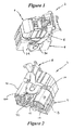
- Figure 1 is a top perspective view of the electrical connector assembly of the present invention
- Figure 2 is a lower perspective view of the connector assembly of Fig. 1 ;
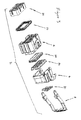
- Figure 3 is an exploded view of the assembly of either Figs. 1 or 2 ;
- Figure 4 is a perspective view similar to that of Fig. 1 showing the lever in position to be received in the connector housing of the embodiment of Figs. 1 or 2 ;
- Figure 5 is a perspective view of the lever shown in Fig. 4 ;
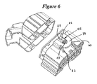
- Figure 6 is a figure showing the wire dress cover exploded from a connector housing.
- an electrical connector assembly is shown at 2 which generally comprises a housing member 4, a wire dress cover 6 and a mating assist member 8 in the form of a lever.
- the housing member 4 is generally comprised of a front mating face 10, sidewalls 12 and 14, end walls 16 and 18 and a top wall at 19.
- Fig. 3 the connector assembly 2 will be described in greater detail.
- housing member 4, wire dress cover 6 and mating assist member 8 are shown exploded away from each other but poised for connection thereto.
- the assembly 2 further comprises a terminal position assurance member (TPA) 20, a peripheral seal 22, a mat (or interfacial) seal 24, a mat seal cover 26 and a connector position assurance member 30. All of these items will not be described in detail in this application, but are further described in simultaneously filed patent applications, US Serial Nos. 11/810,288 and 11/810,232 .
- housing 4 generally includes a shroud 36 formed on each sidewall 12 and 14, where shroud 36 includes a shroud wall 38 ( Figure 4 ) spaced apart from sidewalls 12 and 14 by way of walls 40.
- Shroud wall 38 is spaced apart from sidewalls 12 and 14 to form an opening 42 for receipt of the mating assist member 8 as described herein.
- An outer surface of shroud wall 38 includes a receiving area generally shown as 44 which includes a U-shaped recess 46 having an elongate slot 48 extending along the length of the U-shaped recess, which opens into an enlarged opening 49.
- An inside surface of the shroud wall 38 includes a channel 50 and a stubbing surface 52, for the proper receipt of the mating assist member 8 as described herein.
- the sidewalls 12 and 14 include a bearing bar 58 in alignment with the elongate slot 48 as described herein.
- a lower edge 60 of shroud wall 38 is shown generally as including an arcuate shape.
- mating assist member 8 generally includes individual lever arms 70 with a connecting member 72 forming a lever handle where each of the lever arms 70 includes a free end at 74.
- the individual lever arms 70 include mating assist portions 76 located on the inside surface of the lever arms, and which are preferably in the form of gear teeth such as 78 to drivingly engage complementary gears on a complementary header connector (not shown) to draw the two connectors into mating engagement.
- Mounting studs 80 are positioned on the opposite sides of the mating assist portions 76, and are receivable in U-shaped recesses 46 as described herein.
- the mounting studs 80 include shank portions 82 having flattened sidewall portions 84 with an enlarged stud 86 positioned above shank portion 82.
- a projection 88 is positioned on an outside surface of the lever arm adjacent to the shank portion 84.
- a lever protrusion 90 is positioned outwardly of the mounting studs 80, towards the free end.
- mating assist member 8 is shown poised for receipt within the housing.
- protrusions 90 are positioned within channel 50 which orients the mating assist member 8 in the proper direction relative to housing 4.
- Stubbing surface 52 prevents incorrect assembly of the mating assist member 8, if it were attempted to install the mating assist member 8 backwards.
- movement of the mating assist member 8 towards end wall 16 of housing 4 positions flattened sidewall portions 84 of shank portion 82 within slot 48 ( Fig. 6 ) of the receiving areas 46.
- lever protrusions 90 will snap past the edge 60 of shroud 36 and be trapped thereby as shown for example in Fig. 2 .
- the projections 90 are positioned beyond arcuate surfaces 60 and retain the mating assist member 8 within shroud 36, during the pivotal movement of mating assist member 8.
- shank portion 82 is received within the circular opening 49 allowing the lever to be moved clockwise and counterclockwise but yet be trapped in place by lever protrusions 90 on each side thereof.
- the mating assist member 8 may be removed by depressing the projections 90, to allow the lever arms 70 to be withdrawn from the receiving areas 44.
- lever arms 70 are positioned adjacent to bearing bars 58 ( Fig. 4 ) and together with projections 88 which are interference fit against an inside surface of wall 38, take up any clearance, so that there is no rattling between the lever arms 70 and the housing 4.
- lever assist member 8 As the lever assist member 8, and the mating assist portions 76 are positioned inside the shroud 36, these members are protected thereby from forces acting upon them.
Landscapes
- Details Of Connecting Devices For Male And Female Coupling (AREA)
Applications Claiming Priority (2)
| Application Number | Priority Date | Filing Date | Title |
|---|---|---|---|
| US91943707P | 2007-03-22 | 2007-03-22 | |
| US11/810,373 US7467958B2 (en) | 2007-03-22 | 2007-06-05 | Electrical connector having lever with protective shroud |
Publications (3)
| Publication Number | Publication Date |
|---|---|
| EP1973203A2 true EP1973203A2 (fr) | 2008-09-24 |
| EP1973203A3 EP1973203A3 (fr) | 2009-10-28 |
| EP1973203B1 EP1973203B1 (fr) | 2015-05-06 |
Family
ID=39537936
Family Applications (1)
| Application Number | Title | Priority Date | Filing Date |
|---|---|---|---|
| EP20080102822 Active EP1973203B1 (fr) | 2007-03-22 | 2008-03-20 | Connecteur électrique disposant d'un levier plateau de protection |
Country Status (5)
| Country | Link |
|---|---|
| US (1) | US7467958B2 (fr) |
| EP (1) | EP1973203B1 (fr) |
| CN (1) | CN101304137B (fr) |
| ES (1) | ES2539949T3 (fr) |
| MX (1) | MX2008003851A (fr) |
Families Citing this family (7)
| Publication number | Priority date | Publication date | Assignee | Title |
|---|---|---|---|---|
| US7867028B2 (en) * | 2008-05-07 | 2011-01-11 | Tyco Electronics Corporation | Remote detection of partially seated electrical terminal |
| US9217837B2 (en) * | 2012-09-15 | 2015-12-22 | Finisar Corporation | Latch mechanism for communications module |
| JP2016207414A (ja) * | 2015-04-21 | 2016-12-08 | 住友電装株式会社 | コネクタ |
| JP2018206617A (ja) * | 2017-06-06 | 2018-12-27 | 住友電装株式会社 | レバー式コネクタ |
| EP3496210B1 (fr) * | 2017-12-07 | 2023-03-01 | Aptiv Technologies Limited | Connecteur à fiches électrique |
| JP7618947B2 (ja) * | 2020-06-16 | 2025-01-22 | ヒロセ電機株式会社 | 液状物質の侵入を防止するコネクタ組立体及びコネクタ組立体を用いた電子装置 |
| CN118431810B (zh) * | 2024-07-04 | 2024-10-29 | 比亚迪股份有限公司 | 护套、连接器及车辆 |
Family Cites Families (12)
| Publication number | Priority date | Publication date | Assignee | Title |
|---|---|---|---|---|
| US5938458A (en) * | 1998-06-17 | 1999-08-17 | Molex Incorporated | Lever type electrical connector |
| EP1037326A3 (fr) * | 1999-03-08 | 2001-02-07 | The Whitaker Corporation | Connecteur électrique commandé par un levier |
| US6368125B1 (en) * | 1999-05-18 | 2002-04-09 | Tyco Electronics Corporation | Connector with lever |
| JP3777083B2 (ja) * | 2000-07-11 | 2006-05-24 | 株式会社オートネットワーク技術研究所 | コネクタ及びコネクタ構造 |
| US20040192090A1 (en) * | 2003-03-28 | 2004-09-30 | Flowers Robert J. | Lever type electrical connector with CPA member |
| DE10332893A1 (de) * | 2003-07-19 | 2005-02-10 | Leopold Kostal Gmbh & Co Kg | Elektrischer Steckverbinder |
| JP4001113B2 (ja) * | 2004-01-14 | 2007-10-31 | 住友電装株式会社 | レバー式コネクタ |
| US6899554B1 (en) * | 2004-04-19 | 2005-05-31 | Jst Corporation | Dual action mechanical assisted connector |
| JP4229282B2 (ja) * | 2004-04-28 | 2009-02-25 | タイコエレクトロニクスアンプ株式会社 | レバー式コネクタ |
| US7052293B2 (en) * | 2004-08-20 | 2006-05-30 | Molex Incorporated | Lever type electrical connector |
| US7267564B2 (en) * | 2005-12-01 | 2007-09-11 | Molex Incorporated | Lever type electrical connector |
| JP4497108B2 (ja) * | 2006-03-02 | 2010-07-07 | 住友電装株式会社 | レバー式コネクタ |
-
2007
- 2007-06-05 US US11/810,373 patent/US7467958B2/en active Active
-
2008
- 2008-03-19 MX MX2008003851A patent/MX2008003851A/es active IP Right Grant
- 2008-03-20 EP EP20080102822 patent/EP1973203B1/fr active Active
- 2008-03-20 ES ES08102822.7T patent/ES2539949T3/es active Active
- 2008-03-24 CN CN2008101277798A patent/CN101304137B/zh active Active
Also Published As
| Publication number | Publication date |
|---|---|
| CN101304137B (zh) | 2012-04-25 |
| US7467958B2 (en) | 2008-12-23 |
| CN101304137A (zh) | 2008-11-12 |
| US20080233790A1 (en) | 2008-09-25 |
| EP1973203B1 (fr) | 2015-05-06 |
| EP1973203A3 (fr) | 2009-10-28 |
| MX2008003851A (es) | 2009-02-27 |
| ES2539949T3 (es) | 2015-07-07 |
Similar Documents
| Publication | Publication Date | Title |
|---|---|---|
| EP1859513B2 (fr) | Assemblage de connecteur associe a un levier avec dispositif de fixation de la position | |
| EP1856771B1 (fr) | Ensemble de connecteur electrique comprenant une assistance par levier comportant un mecanisme de verrouillage a maintien vers le bas | |
| EP1973203B1 (fr) | Connecteur électrique disposant d'un levier plateau de protection | |
| EP2235799B1 (fr) | Connecteur électrique | |
| EP1914847B1 (fr) | Connecteur de câble pour porte de véhicule | |
| EP0818855B1 (fr) | Connecteur | |
| EP1930985A2 (fr) | Connecteur électrique | |
| EP2705579B1 (fr) | Ensemble connecteur | |
| EP2975699B1 (fr) | Partie de boîtier pour connecteur électrique enfichable | |
| EP2149938B1 (fr) | Connecteur de type levier | |
| CN101218714B (zh) | 带有接线端位置保证装置的连接器组件 | |
| EP1091451B1 (fr) | Connecteur | |
| EP4228100B1 (fr) | Ensemble connecteur avec caractéristique de détection de borne non positionnée | |
| EP1821372A1 (fr) | Connecteur et méthode de montage | |
| US7261575B2 (en) | Electrical connector and electrical connector assembly having selectively includable lever assist | |
| EP1601063B1 (fr) | Dispositif de raccordement | |
| JPH08315913A (ja) | 電気コネクタ及びそれを使用するコネクタ組立体 | |
| CN112688105B (zh) | 连接器 | |
| EP4641845A1 (fr) | Agencement de levier réutilisable et extensible ayant un élément anti-surblocage | |
| US20240372289A1 (en) | Dual locking system | |
| JP2007115632A (ja) | ロック機構付き電気コネクタ | |
| MX2008010759A (en) | Lever mated connector assembly | |
| JP2005065420A (ja) | 電気接続箱の防水構造 |
Legal Events
| Date | Code | Title | Description |
|---|---|---|---|
| PUAI | Public reference made under article 153(3) epc to a published international application that has entered the european phase |
Free format text: ORIGINAL CODE: 0009012 |
|
| AK | Designated contracting states |
Kind code of ref document: A2 Designated state(s): AT BE BG CH CY CZ DE DK EE ES FI FR GB GR HR HU IE IS IT LI LT LU LV MC MT NL NO PL PT RO SE SI SK TR |
|
| AX | Request for extension of the european patent |
Extension state: AL BA MK RS |
|
| PUAL | Search report despatched |
Free format text: ORIGINAL CODE: 0009013 |
|
| AK | Designated contracting states |
Kind code of ref document: A3 Designated state(s): AT BE BG CH CY CZ DE DK EE ES FI FR GB GR HR HU IE IS IT LI LT LU LV MC MT NL NO PL PT RO SE SI SK TR |
|
| AX | Request for extension of the european patent |
Extension state: AL BA MK RS |
|
| 17P | Request for examination filed |
Effective date: 20100427 |
|
| AKX | Designation fees paid |
Designated state(s): DE ES FR GB IT |
|
| 17Q | First examination report despatched |
Effective date: 20100628 |
|
| GRAP | Despatch of communication of intention to grant a patent |
Free format text: ORIGINAL CODE: EPIDOSNIGR1 |
|
| INTG | Intention to grant announced |
Effective date: 20150203 |
|
| GRAS | Grant fee paid |
Free format text: ORIGINAL CODE: EPIDOSNIGR3 |
|
| GRAA | (expected) grant |
Free format text: ORIGINAL CODE: 0009210 |
|
| AK | Designated contracting states |
Kind code of ref document: B1 Designated state(s): DE ES FR GB IT |
|
| REG | Reference to a national code |
Ref country code: GB Ref legal event code: FG4D |
|
| REG | Reference to a national code |
Ref country code: DE Ref legal event code: R096 Ref document number: 602008038009 Country of ref document: DE Effective date: 20150618 |
|
| REG | Reference to a national code |
Ref country code: ES Ref legal event code: FG2A Ref document number: 2539949 Country of ref document: ES Kind code of ref document: T3 Effective date: 20150707 |
|
| REG | Reference to a national code |
Ref country code: DE Ref legal event code: R097 Ref document number: 602008038009 Country of ref document: DE |
|
| PLBE | No opposition filed within time limit |
Free format text: ORIGINAL CODE: 0009261 |
|
| STAA | Information on the status of an ep patent application or granted ep patent |
Free format text: STATUS: NO OPPOSITION FILED WITHIN TIME LIMIT |
|
| REG | Reference to a national code |
Ref country code: FR Ref legal event code: PLFP Year of fee payment: 9 |
|
| 26N | No opposition filed |
Effective date: 20160209 |
|
| REG | Reference to a national code |
Ref country code: FR Ref legal event code: PLFP Year of fee payment: 10 |
|
| REG | Reference to a national code |
Ref country code: FR Ref legal event code: PLFP Year of fee payment: 11 |
|
| REG | Reference to a national code |
Ref country code: FR Ref legal event code: CD Owner name: TYCO ELECTRONICS CORPORATION, US Effective date: 20180626 |
|
| REG | Reference to a national code |
Ref country code: ES Ref legal event code: PC2A Owner name: TE CONNECTIVITY CORPORATION Effective date: 20181005 |
|
| REG | Reference to a national code |
Ref country code: DE Ref legal event code: R082 Ref document number: 602008038009 Country of ref document: DE Representative=s name: MARKS & CLERK (LUXEMBOURG) LLP, LU Ref country code: DE Ref legal event code: R081 Ref document number: 602008038009 Country of ref document: DE Owner name: TE CONNECTIVITY CORPORATION, BERWYN, US Free format text: FORMER OWNER: TYCO ELECTRONICS CORPORATION, MIDDLETOWN, PA., US |
|
| PGFP | Annual fee paid to national office [announced via postgrant information from national office to epo] |
Ref country code: GB Payment date: 20190320 Year of fee payment: 12 Ref country code: IT Payment date: 20190326 Year of fee payment: 12 |
|
| PGFP | Annual fee paid to national office [announced via postgrant information from national office to epo] |
Ref country code: FR Payment date: 20190213 Year of fee payment: 12 |
|
| PGFP | Annual fee paid to national office [announced via postgrant information from national office to epo] |
Ref country code: ES Payment date: 20190401 Year of fee payment: 12 |
|
| PG25 | Lapsed in a contracting state [announced via postgrant information from national office to epo] |
Ref country code: FR Free format text: LAPSE BECAUSE OF NON-PAYMENT OF DUE FEES Effective date: 20200331 |
|
| GBPC | Gb: european patent ceased through non-payment of renewal fee |
Effective date: 20200320 |
|
| PG25 | Lapsed in a contracting state [announced via postgrant information from national office to epo] |
Ref country code: GB Free format text: LAPSE BECAUSE OF NON-PAYMENT OF DUE FEES Effective date: 20200320 |
|
| REG | Reference to a national code |
Ref country code: ES Ref legal event code: FD2A Effective date: 20210805 |
|
| PG25 | Lapsed in a contracting state [announced via postgrant information from national office to epo] |
Ref country code: IT Free format text: LAPSE BECAUSE OF NON-PAYMENT OF DUE FEES Effective date: 20200320 |
|
| PG25 | Lapsed in a contracting state [announced via postgrant information from national office to epo] |
Ref country code: ES Free format text: LAPSE BECAUSE OF NON-PAYMENT OF DUE FEES Effective date: 20200321 |
|
| PGFP | Annual fee paid to national office [announced via postgrant information from national office to epo] |
Ref country code: DE Payment date: 20260102 Year of fee payment: 19 |