EP1973237A2 - Contrôle d'alimentation pour des systèmes d'entrées multiples d'informations sur l'état du canal partiel (CSI), et de sortie multiples (MIMO) - Google Patents
Contrôle d'alimentation pour des systèmes d'entrées multiples d'informations sur l'état du canal partiel (CSI), et de sortie multiples (MIMO) Download PDFInfo
- Publication number
- EP1973237A2 EP1973237A2 EP08012143A EP08012143A EP1973237A2 EP 1973237 A2 EP1973237 A2 EP 1973237A2 EP 08012143 A EP08012143 A EP 08012143A EP 08012143 A EP08012143 A EP 08012143A EP 1973237 A2 EP1973237 A2 EP 1973237A2
- Authority
- EP
- European Patent Office
- Prior art keywords
- spectral efficiency
- transmit power
- transmission
- data
- transmission channels
- Prior art date
- Legal status (The legal status is an assumption and is not a legal conclusion. Google has not performed a legal analysis and makes no representation as to the accuracy of the status listed.)
- Withdrawn
Links
- 230000036961 partial effect Effects 0.000 title description 13
- 238000000034 method Methods 0.000 claims abstract description 245
- 230000003595 spectral effect Effects 0.000 claims abstract description 141
- 238000012545 processing Methods 0.000 claims abstract description 130
- 238000004891 communication Methods 0.000 claims abstract description 50
- 230000005540 biological transmission Effects 0.000 claims description 99
- 230000008569 process Effects 0.000 claims description 56
- 230000015654 memory Effects 0.000 claims description 6
- 238000004590 computer program Methods 0.000 claims description 2
- 238000001514 detection method Methods 0.000 abstract description 194
- VMAKIACTLSBBIY-BOPFTXTBSA-N (z)-3-(4-chloroanilino)-n-(4-chlorophenyl)-2-(3-methyl-1,2-oxazol-5-yl)prop-2-enamide Chemical compound O1N=C(C)C=C1C(\C(=O)NC=1C=CC(Cl)=CC=1)=C\NC1=CC=C(Cl)C=C1 VMAKIACTLSBBIY-BOPFTXTBSA-N 0.000 abstract 1
- 239000011159 matrix material Substances 0.000 description 48
- 238000010586 diagram Methods 0.000 description 17
- 239000002131 composite material Substances 0.000 description 15
- 230000006870 function Effects 0.000 description 14
- 230000004044 response Effects 0.000 description 9
- 230000001419 dependent effect Effects 0.000 description 8
- 230000000694 effects Effects 0.000 description 8
- 230000008859 change Effects 0.000 description 7
- 238000005562 fading Methods 0.000 description 7
- 238000011895 specific detection Methods 0.000 description 6
- 230000001143 conditioned effect Effects 0.000 description 5
- 230000002829 reductive effect Effects 0.000 description 5
- 230000002441 reversible effect Effects 0.000 description 5
- 230000006872 improvement Effects 0.000 description 4
- 230000008878 coupling Effects 0.000 description 3
- 238000010168 coupling process Methods 0.000 description 3
- 238000005859 coupling reaction Methods 0.000 description 3
- 230000008901 benefit Effects 0.000 description 2
- 238000012512 characterization method Methods 0.000 description 2
- 230000007423 decrease Effects 0.000 description 2
- 230000003116 impacting effect Effects 0.000 description 2
- 238000005457 optimization Methods 0.000 description 2
- 239000007787 solid Substances 0.000 description 2
- 206010015995 Eyelid ptosis Diseases 0.000 description 1
- 238000007476 Maximum Likelihood Methods 0.000 description 1
- 230000003044 adaptive effect Effects 0.000 description 1
- 239000000654 additive Substances 0.000 description 1
- 230000000996 additive effect Effects 0.000 description 1
- 238000013459 approach Methods 0.000 description 1
- 238000003491 array Methods 0.000 description 1
- 230000006399 behavior Effects 0.000 description 1
- 230000000295 complement effect Effects 0.000 description 1
- 125000004122 cyclic group Chemical group 0.000 description 1
- 230000003247 decreasing effect Effects 0.000 description 1
- 230000002939 deleterious effect Effects 0.000 description 1
- 239000006185 dispersion Substances 0.000 description 1
- 230000002452 interceptive effect Effects 0.000 description 1
- 238000012886 linear function Methods 0.000 description 1
- 238000013507 mapping Methods 0.000 description 1
- 230000007246 mechanism Effects 0.000 description 1
- 238000012986 modification Methods 0.000 description 1
- 230000004048 modification Effects 0.000 description 1
- 238000011867 re-evaluation Methods 0.000 description 1
- 238000011084 recovery Methods 0.000 description 1
- 238000009738 saturating Methods 0.000 description 1
- 238000006467 substitution reaction Methods 0.000 description 1
Images






Classifications
-
- H—ELECTRICITY
- H04—ELECTRIC COMMUNICATION TECHNIQUE
- H04B—TRANSMISSION
- H04B7/00—Radio transmission systems, i.e. using radiation field
- H04B7/02—Diversity systems; Multi-antenna system, i.e. transmission or reception using multiple antennas
- H04B7/04—Diversity systems; Multi-antenna system, i.e. transmission or reception using multiple antennas using two or more spaced independent antennas
- H04B7/0413—MIMO systems
- H04B7/0417—Feedback systems
-
- H—ELECTRICITY
- H04—ELECTRIC COMMUNICATION TECHNIQUE
- H04B—TRANSMISSION
- H04B7/00—Radio transmission systems, i.e. using radiation field
- H04B7/02—Diversity systems; Multi-antenna system, i.e. transmission or reception using multiple antennas
- H04B7/04—Diversity systems; Multi-antenna system, i.e. transmission or reception using multiple antennas using two or more spaced independent antennas
- H04B7/06—Diversity systems; Multi-antenna system, i.e. transmission or reception using multiple antennas using two or more spaced independent antennas at the transmitting station
- H04B7/0613—Diversity systems; Multi-antenna system, i.e. transmission or reception using multiple antennas using two or more spaced independent antennas at the transmitting station using simultaneous transmission
- H04B7/0615—Diversity systems; Multi-antenna system, i.e. transmission or reception using multiple antennas using two or more spaced independent antennas at the transmitting station using simultaneous transmission of weighted versions of same signal
- H04B7/0619—Diversity systems; Multi-antenna system, i.e. transmission or reception using multiple antennas using two or more spaced independent antennas at the transmitting station using simultaneous transmission of weighted versions of same signal using feedback from receiving side
-
- H—ELECTRICITY
- H04—ELECTRIC COMMUNICATION TECHNIQUE
- H04L—TRANSMISSION OF DIGITAL INFORMATION, e.g. TELEGRAPHIC COMMUNICATION
- H04L1/00—Arrangements for detecting or preventing errors in the information received
- H04L1/0001—Systems modifying transmission characteristics according to link quality, e.g. power backoff
-
- H—ELECTRICITY
- H04—ELECTRIC COMMUNICATION TECHNIQUE
- H04L—TRANSMISSION OF DIGITAL INFORMATION, e.g. TELEGRAPHIC COMMUNICATION
- H04L1/00—Arrangements for detecting or preventing errors in the information received
- H04L1/02—Arrangements for detecting or preventing errors in the information received by diversity reception
- H04L1/06—Arrangements for detecting or preventing errors in the information received by diversity reception using space diversity
-
- H—ELECTRICITY
- H04—ELECTRIC COMMUNICATION TECHNIQUE
- H04W—WIRELESS COMMUNICATION NETWORKS
- H04W52/00—Power management, e.g. Transmission Power Control [TPC] or power classes
- H04W52/04—Transmission power control [TPC]
- H04W52/38—TPC being performed in particular situations
- H04W52/42—TPC being performed in particular situations in systems with time, space, frequency or polarisation diversity
Definitions
- the present invention relates generally to data communication, and more specifically to techniques for controlling transmit power in multi-channel communication systems (e. g. , multiple-input, multiple-output (MIMO) systems) that utilize partial channel-state information (CSI).
- multi-channel communication systems e. g. , multiple-input, multiple-output (MIMO) systems
- CSI channel-state information
- an RF modulated signal from a transmitter may reach a receiver via a number of propagation paths.
- the characteristics of the propagation paths typically vary over time due to a number of factors such as fading and multipath.
- multiple transmit and receive antennas may be used. If the propagation paths between the transmit and receive antennas are linearly independent (i. e. , a transmission on one path is not formed as a linear combination of the transmissions on other paths), which is generally true to at least an extent, then the likelihood of correctly receiving a data transmission increases as the number of antennas increases.
- a multiple-input, multiple-output (MIMO) communication system employs multiple (NT) transmit antennas and multiple (NR) receive antennas for data transmission.
- a MIMO channel formed by the NT transmit and NR receive antennas may be decomposed into NS independent channels, with Ns ⁇ min ⁇ NT, NR ⁇ .
- Each of the NS independent channels is also referred to as a spatial subchannel (or a transmission channel) of the MIMO channel and corresponds to a dimension.
- the MIMO system can provide improved performance (e. g. , increased transmission capacity) if the additional dimensionalities created by the multiple transmit and receive antennas are utilized.
- an independent data stream may be transmitted on each of the NS spatial subchannels to increase system throughput.
- CSI channel-state information
- CSI may be categorized as either"full CSI"or"partial CSI".
- Full CSI includes sufficient characterization (e. g. , amplitude and phase) of the propagation path between each transmit-receive antenna pair in a (NR x NT) MIMO matrix.
- Full CSI may not be available or practical for many MIMO systems.
- Partial CSI may comprise, for example, the signal-to-noise-and-interference ratios (SNRs) of the spatial subchannels, which may be estimated by detecting the data streams and/or pilots transmitted on these subchannels.
- SNRs signal-to-noise-and-interference ratios
- Each data stream may then be coded and modulated in accordance with a particular coding and modulation scheme selected based on the subchannel's SNR.
- the spatial subchannels of a MIMO system may experience different channel conditions (e. g. , different fading and multipath effects) and may achieve different SNRs for a given amount of transmit power. Consequently, the data rates that may be supported by the spatial subchannels may be different from subchannel to subchannel. Moreover, the channel conditions typically vary with time. As a result, the data rates supported by the spatial subchannels also vary with time.
- a key challenge in a MIMO system is the determination of the transmit powers to use for the data transmissions on the spatial subchannels based on the channel conditions.
- the goal of this transmit power control should be to maximize spectral efficiency while meeting other system objectives, such as achieving a particular target frame error rate (FER) for each data stream, minimizing interference, and so on.
- FER target frame error rate
- the data rate may be used for any given data stream.
- a set of discrete data rates may be supported by the system, and the maximum data rate from among these discrete data rates may be considered as the maximum spectral efficiency for any given data stream.
- utilizing more transmit power than necessary for each data stream to achieve the target FER at the maximum data rate would result in an ineffective use of the additional transmit power.
- the excess transmit power may result in a lower FER, this improvement in FER may not be considered substantial since the target FER has already been achieved.
- the excess transmit power for a given data stream may result in additional interference to other data streams, which may then degrade the performance of these data streams.
- the post-detection SNRs of a number of data streams may be initially estimated.
- the transmit power for each data stream is then determined by taking into account the specific receiver processing technique used to detect the data streams at the receiver.
- the new transmit powers attempt to maintain the post-detection SNRs of the data streams either (1) at the SNR, Yllt, needed to achieve the maximum allowed spectral efficiency, for any SNR that exceeds Yset X or (2) at or near the target SNR needed for a specified spectral efficiency.
- a method for controlling the transmit power for a number of data streams in a wireless multi-channel (e. g. , MIMO) communication system.
- a number of received symbol streams are processed in accordance with a particular receiver processing technique (e. g. , a CCMI, CCMI-SC, MMSE, MMSE-SC, or some other technique, as described below) to provide a number of detected data streams.
- the post-detection SNRs of the detected data streams are estimated, and each SNR that exceeds a setpoint is identified. This setpoint may correspond to the SNR needed to achieve the maximum allowed spectral efficiency (e. g.
- a new (or adjusted) transmit power for each detected data stream associated with a post-detection SNR that exceeds the setpoint is determined and used for the data stream.
- the post-detection SNRs of the data streams are dependent on the specific receiver processing technique used at the receiver to detect the data streams. Moreover, the relationships between transmit powers and post-detection SNRs for the detected data streams may or may not be decorrelated. Different power control schemes are provided herein for different classes of receiver processing techniques with different characteristics. In a first class (which includes the CCMI and CCMI-SC techniques), 020154 4 the detected data streams are decoupled by the receiver processing, and changing the transmit power of one data stream does not affect the post-detection SNRs of the other data streams. The transmit power for each detected data stream may then be determined without regards to the transmit powers for the other data streams.
- the post-detection SNR of a given data stream may be coupled to the transmit powers of the other data streams, and a change in the transmit power for one data stream may affect the post-detection SNRs of the other data streams.
- the transmit powers for the data streams may then be determined in a manner to take into account this inter-dependency, and the power adjustment may be iterated as many times as necessary to achieve the desired results.
- the invention further provides methods, processors, receiver units, transmitter units, terminals, base stations, systems, and other apparatuses and elements that implement various aspects, embodiments, and features of the invention, as described in further detail below.
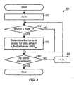
- FIG. 1 is a block diagram of an embodiment of a transmitter system and a receiver system in a MIMO system; [1015] FIG. 2 shows two plots for spectral efficiency versus post-detection SNR; [1016] FIG. 3 is a flow diagram of a process for adjusting the transmit power to achieve a set of post-detection SNRs for a CCMI receiver; [1017] FIG. 4 is a flow diagram illustrating the CCMI-SC receiver processing technique; [1018] FIG.
- FIG. 5 is a flow diagram of a process for maximizing spectral efficiency while minimizing the total required transmit power for the CCMI-SC receiver;
- FIG. 6 is a flow diagram of a process for adjusting the transmit power to achieve a set of post-detection SNRs for an MMSE receiver; 020154 5
- FIG. 7 is a flow diagram of a process for adjusting the transmit power to achieve a set of post-detection SNRs for an MMSE-SC receiver;
- FIG. 8 shows a plot of spectral efficiency versus post-detection SNR for a communication system that supports a set of discrete data rates; [1022] FIGS.
- FIGS. 10A and 10B are block diagrams of a RX MIMO/data processor that respectively implements and does not implement the successive cancellation receiver processing technique; and [1023] FIGS. 10A and 10B are block diagrams of two spatial processors that implement the CCMI and MMSE techniques, respectively.
- the techniques described herein for controlling transmit power for data transmissions may be used for various multi-channel communication systems.
- Such multi-channel communication systems include multiple-input, multiple-output (MIMO) communication systems, orthogonal frequency division multiplexing (OFDM) communication systems, MIMO systems that utilize OFDM (i. e., MIMO-OFDM systems), and others.
- MIMO multiple-input, multiple-output
- OFDM orthogonal frequency division multiplexing
- MIMO systems that utilize OFDM i. e., MIMO-OFDM systems
- the multi-channel communication systems may also implement code division multiple access (CDMA), time division multiple access (TDMA), frequency division multiple access (FDMA), or some other multiple access techniques.
- CDMA code division multiple access
- TDMA time division multiple access
- FDMA frequency division multiple access
- Multiple-access communication systems can support concurrent communication with a number of terminals (i. e. , users).
- terminals i. e. , users
- MIMO system such as a multiple-antenna wireless communication system.
- FIG. 1 is a block diagram of an embodiment of a transmitter system 110 and a receiver system 150 in a MIMO system 100.
- traffic data for a number of data streams is provided from a data source 112 to a transmit (TX) data processor 114.
- TX data processor 114 formats, codes, and interleaves the traffic data for each data stream based on a particular coding scheme selected for that data stream to provide coded data.
- the coded traffic data for all data streams may be multiplexed with pilot data (e. g. , using time division multiplex (TDM) or code division multiplex (CDM) ) in all or a subset of the transmission channels to be used for data transmission.
- TDM time division multiplex
- CDM code division multiplex
- the pilot data is typically a known data pattern that is processed in a known manner, if at all.
- the multiplexed pilot and coded traffic data for each data stream is then modulated (i. e. , symbol mapped) based on a particular modulation scheme (e. g., BPSK, QSPK, M-PSK, or M-QAM) selected for that data stream to provide modulation symbols.
- a particular modulation scheme e. g., BPSK, QSPK, M-PSK, or M-QAM
- the data rate, coding, interleaving, and modulation for each data stream may be determined by controls provided by a controller 130.
- TX MIMO processor 120 scales the modulation symbols for each data stream by a respective weight determined based on the amount of transmit power to be used for that data stream.
- TX MIMO processor 120 then demultiplexes the scaled modulation symbols into (up to) NT transmit symbol streams, one transmit symbol stream for each of the (up to) NT transmit antennas to be used for data transmission.
- the up to NT transmit symbol streams are then provided to transmitters (TMTR) 122a through 122t.
- Each transmitter 122 for a selected transmit antenna receives and processes a respective transmit symbol stream.
- each transmitter transforms the scaled modulation symbols (e. g. , using the inverse Fourier transform) to form OFDM symbols, and may further append a cyclic prefix to each OFDM symbol to form a corresponding transmission symbol.
- Each transmitter converts the symbol stream into one or more analog signals and further conditions (e. g. , amplifies, filters, and quadrature modulates) the analog signals to generate a modulated signal suitable for transmission over the MIMO channel. Up to NT modulated signals from transmitters 122a through 122t are then transmitted from up to NT antennas 124a through 124t, respectively.
- the transmitted modulated signals are received by NR antennas 152a through 152r, and the received signal from each antenna 152 is provided to a respective receiver (RCVR) 154.
- Each receiver 154 conditions (e. g. , filters, amplifies, and downconverts) the received signal and digitizes the conditioned signal to provide a respective stream of samples.
- Each sample stream may further be processed (e. g. , demodulated with a recovered pilot) to obtain a corresponding stream of received symbols.
- RX MIMO/data processor 160 then receives and processes the NR received symbol streams to provide Ns"detected"data streams.
- RX MIMO/data processor 160 may perform spatial or space-time processing on the NR received symbol 020154 7 streams using any of a number of spatial and space-time receiver processing techniques, some of which are described in further detail below.
- Each detected data stream includes symbols that are estimates of the modulation symbols transmitted for that data stream.
- RX MIMO/data processor 160 then demodulates, deinterleaves, and decodes each detected data stream to recover the traffic data for the data stream.
- the processing by RX MIMO/data processor 160 is complementary to that performed by TX MIMO processor 120 and TX data processor 114 at transmitter system 110.
- RX MIMO processor 160 may further derive an estimate of the signal-to-noise-and-interference ratios (SNRs) of the data streams, and possibly other channel characteristics, and provide these quantities to a controller 170.
- SNRs signal-to-noise-and-interference ratios
- RX MIMO/data processor 160 may also provide the status of each received frame or packet, one or more other performance metrics indicative of the decoded results, and possibly other information.
- Controller 170 collects channel state information (CSI), which may comprise all or some of the information received from RX MIMO/data processor 160.
- CSI channel state information
- the CSI is then processed by a TX data processor 178, modulated by a modulator 180, conditioned by transmitters 154a through 154r, and transmitted back to transmitter system 110.
- the modulated signals from receiver system 150 are received by antennas 124, conditioned by receivers 122, demodulated by a demodulator 140, and processed by a RX data processor 142 to recover the CSI reported by the receiver system.
- the CSI is then provided to controller 130 and used to generate various controls for TX data processor 114 and TX MIMO processor 120.
- Controllers 130 and 170 direct the operation at the transmitter and receiver systems, respectively.
- Memories 132 and 172 provide storage for program codes and data used by controllers 130 and 170, respectively.
- the MIMO channel formed by the NT transmit and NR receive antennas may be decomposed into NS independent channels, with NS ⁇ min ⁇ NT NR ⁇ .
- NS independent channels is also referred to as a spatial subchannel (or a transmission channel) of the MIMO channel.
- the number of spatial subchannels is determined by the number of eigenmodes for the MIMO channel, which in turn is dependent on a channel response matrix, H, that describes the response between the NT transmit and NR receive antennas.
- each data stream may be transmitted from one or multiple transmit antennas. However, for simplicity, much of the description below assumes that one data stream is transmitted from each transmit antenna.
- AWGN additive white Gaussian noise
- the diagonal matrix, A may be expressed as: where Ai represents the amplitude of the data stream xi transmitted from the i-th transmit antenna.
- the amplitude Ai and the transmit power Pi of data stream xi are related by Pi#Ai2.
- the MIMO channel is assumed to be a flat-fading, narrowband channel.
- the elements of the channel response matrix, H are scalars, and the coupling, hj, j, between each transmit-receive antenna pair can be represented by a single scalar value.
- the power control techniques described herein may also be used for a frequency selective channel having different channel gains at different frequencies.
- the operating bandwidth may be divided into a number of (equal or unequal width) frequency bands such that each band may be considered as a flat-fading channel. The response of the individual bands may then be considered in performing power control.
- the NS data streams transmitted from the NT transmit antennas interfere with each other at the receiver.
- a given data stream transmitted from one transmit antenna may be received by all NR receive antennas at different amplitudes and phases.
- Each received signal may then include a component from each of the NT transmitted data streams.
- the NR received signals would collectively include all NT transmitted data streams; however, these data streams are dispersed among the received signals.
- Various processing techniques may be used at the transmitter and receiver to ameliorate the effects of interference. These processing techniques depend on the available CSI and the characteristics of the MIMO channel [1042] The processing at the transmitter and receiver is dependent on the available CSI, which may be categorized as either"full CSI"or"partial CSI".
- Full CSI includes sufficient characterization (e. g. , amplitude and phase) across the entire system bandwidth for the propagation path between each transmit-receive antenna pair in a (NR X NT) MIMO matrix.
- Full CSI may not be available or practical for many 020154 10 systems.
- Partial CSI may comprise, for example, the SNRs of the transmission channels.
- each data stream may be coded and modulated in accordance with a particular coding and modulation scheme selected based on the achievable SNR.
- one data stream may be transmitted on each antenna and the transmit power for each data stream may also be adjusted based on the SNR and the selected coding and modulation scheme.
- receiver processing techniques may be used to process the received signals to recover the transmitted data streams.
- These receiver processing techniques may be grouped into two primary categories: spatial and space-time receiver processing techniques (which are also referred to as equalization techniques), and “successive nulling/equalization and interference cancellation”receiver processing technique (which is also referred to as”successive interference cancellation”or"successive cancellation”receiver processing technique).
- the spatial and space-time receiver processing techniques attempt to separate out the transmitted data streams at the receiver.
- Each transmitted data stream may be"detected"by combining the various components of the transmitted data streams included in the NR received signals based on an estimate of the channel response and removing (or canceling) the interference due to the components of the other data streams.
- These receiver processing techniques attempt to either (1) decorrelate the received data streams such that there is no interference from the other data streams or (2) maximize the SNR of each data stream in the presence of noise and interference from the other data streams.
- Each detected data stream is then further processed (e. g., demodulated, deinterleaved, and decoded) to recover the traffic data for the data stream.
- the successive cancellation receiver processing technique attempts to recover the transmitted data streams, one at a time using a spatial or space-time receiver processing technique, and to cancel the interference due to each recovered data stream such that later recovered data streams experience less interference and may be able to achieve higher SNR.
- the successive cancellation receiver processing technique may be used if the interference due to each recovered data stream can be accurately estimated and canceled, which requires error free recovery of the data stream.
- the successive cancellation receiver processing technique generally outperforms the spatial/space-time receiver processing techniques.
- the specific receiver processing technique to be used is typically dependent on the characteristics of the MIMO channel, which may be characterized as either non- dispersive or dispersive.
- a non-dispersive MIMO channel experiences flat fading (i. e., approximately equal amount of attenuation across the system bandwidth), and a dispersive MIMO channel experiences frequency-selective fading (e. g. , different amounts of attenuation across the system bandwidth).
- spatial receiver processing techniques may be used to process the received signals to provide the detected data streams.
- These spatial receiver processing techniques include a channel correlation matrix inversion (CCMI) technique and a minimum mean square error (MMSE) technique.
- CCMI channel correlation matrix inversion
- MMSE minimum mean square error
- Other spatial receiver processing techniques may also be used and are within the scope of the invention.
- space-time receiver processing techniques may be used to process the received signals to provide the detected data streams.
- space-time receiver processing techniques include a MMSE linear equalizer (MMSE-LE), a decision feedback equalizer (DFE), a maximum-likelihood sequence estimator (MLSE), and so on.
- the power control techniques are described specifically for the CCMI and MMSE techniques, each with and without successive cancellation.
- the power control techniques may similarly be applied to other receiver processing techniques, and this is within the scope of the invention.
- the number of resolvable data streams is NS < min ⁇ NTX NR ⁇ when H is a full-rank matrix.
- Each data stream is associated with a particular"post-detection" SNR, Ypost after the spatial or space-time receiver processing at the receiver.
- the post-detection SNRs are dependent on the characteristics of the MIMO channel and may be different for different data streams. If successive cancellation receiver processing technique is used, then the post-detection SNRs may also differ depending on the particular order in which the data streams are detected at the receiver, as described below.
- the post-detection SNR of each data stream contributes to the overall spectral efficiency of the MIMO system.
- the spectral efficiency of a given data stream may be defined based on a particular monotonically increasing function in post- detection SNR.
- One function that may be used for spectral efficiency is the capacity function.
- FIG. 2 shows two plots for spectral efficiency versus post-detection SNR.
- Plot 212 shows spectral efficiency increasing logarithmically with SNR as computed based on equation (5), which assumes that an increase in SNR results in a corresponding increase in spectral efficiency.
- the spectral efficiency may be dictated, for example, by 020154 13 the maximum data rate supported by the system for any given data stream.
- Plot 214 shows spectral efficiency increasing logarithmically at lower SNRs and saturating at Pset which is the upper limit on spectral efficiency. Saturation occurs when an increase in SNR no longer produces an increase in spectral efficiency.
- the SNR at which spectral efficiency saturates may be denoted as (i.e., γset##set).
- the total transmit power, Ptot, available for use for all NT transmit antennas may be initially allocated to the data streams in some manner, as long as the power limit per antenna is not exceeded. For example, if the power limit on each of the NT transmit antennas is PtoJNT and one data stream is transmitted from each antenna, then the total transmit power may be uniformly distributed such that each of the NT transmit antennas is initially allocated PtoJNTv and therefore, each data stream is also allocated Ptot/NT.
- each transmit antenna may be allocated at most P,, tINT, and each data stream is also transmitted at PtotlNT power.
- the total power used at the transmitter is less than Ptor and equal to Ns#Ptot/NT.
- the post-detection SNRs of some data streams may be higher than r,,,,.
- post-detection SNRs above Yset may lower the frame error rate (FER)
- FER frame error rate
- this type of improvement in performance is typically not substantial since the system may already be operating at the target FER or at a low FER.
- the excess transmit power that results in the SNR being higher than Yset is not effectively utilized and also causes additional interference to other data streams.
- the transmit power used for each data stream with a post-detection SNR greater than Yset may thus be reduced so that the new post-detection SNR is at or near Yset.
- the target SNR is the post-detection SNR needed to achieve the target FER for a particular data rate and may also be represented as Yset.
- the transmit power for this data stream may be adjusted either up or down such that the new post-detection SNR approaches the setpoint.
- the setpoint may also be adjusted (e. g. , based on the detected frame errors or erasures) to achieve the target FER.
- the post-detection SNRs of the data streams may be initially estimated.
- the transmit power for each data stream is then determined by taking into account the specific receiver processing technique used to detect the data streams at the receiver.
- the new transmit powers attempt to maintain the post-detection SNRs of the detected data streams at or below the saturation post-detection SNR (for a system with an upper limit on spectral efficiency) or at or near the setpoint (for a system with a specified spectral efficiency).
- the post-detection SNRs of the data streams are dependent on the particular receiver processing technique used at the receiver to detect the data streams. Moreover, the relationships between transmit powers and post-detection SNRs for the detected data streams may be decorrelated or not decorrelated for different receiver processing techniques. Different power control schemes are provided herein for different classes of receiver processing techniques with different characteristics.
- the detected data streams are decoupled by the receiver processing, and changing the transmit power of one data stream does not affect the post-detection SNRs of the other data streams.
- This first class includes the CCMI and CCMI with successive cancellation (i. e., CCMI-SC) receiver processing techniques.
- the post-detection SNR of a given data stream may be coupled to one or more of the other data streams'transmit powers, and a change in transmit power for one data stream may affect the post-detection SNRs of the other data streams.
- This second class includes the MMSE and MMSE with successive cancellation (i. e. , MMSE-SC) receiver processing techniques. Power control for the CCMI, CCMI-SC, MMSE, and MMSE-SC receiver processing techniques are described in further detail below.
- the CCMI receiver processing technique (which is also known as a decorrelation or a zero-forcing technique) is an interference cancellation technique that does not require full CSI at the transmitter.
- the transmitter can transmit an independent data stream from each transmit antenna.
- the receiver first performs a channel matched-filter operation on the received vector, y, which is representative of the received symbol streams.
- the vector x is representative of the detected data streams, which are estimates of the transmitted data streams.
- the post-detection SNR of data stream xi may be expressed as: where Pi is the transmit power for data stream xi, a2 is the noise power at the receiver, and is the i-th diagonal element of R-'. It can be noted that there is no interference term in the denominator in equation (12). This results from the fact that the data streams are decorrelated by the CCMI processing and thus do not interfere with each other.
- a key goal of power control is to use the least amount of transmit power to obtain the highest possible spectral efficiency.
- the CCMI receiver processing provides a set of post-detection SNRs for the detected data streams. As noted above, there may be an upper limit on the spectral efficiency of a given data stream. This spectral efficiency, Psetv corresponds to the SNR y,,,. If the post-detection SNR of any given data stream is greater than y,,,, then the transmit power for that data stream may be adjusted to reduce transmit power without impacting spectral efficiency.
- FIG. 3 is a flow diagram of a process 300 for adjusting the transmit power to achieve a set of post-detection SNRs for a CCMI receiver.
- Process 300 determines the minimum total transmit power needed to achieve a set of post-detection SNRs that maximize spectral efficiency.
- Each post-detection SNR in the set is then examined and the new transmit power, to use for the corresponding data stream is determined starting at step 314.
- γpost (i) is denoted as SNR(i) and Yset is denoted as SNRset.
- the relationship between #i and Yset may be expressed as: [1068]
- the simple relationship seen in equation (14) is a result of the linear relationship between the post-detection SNR and the transmit power, as shown in equation (12).
- step 320 A determination is then made whether or not all post-detection SNRs in the set have been considered (step 320). If the answer is no, then the variable i is incremented (step 322), and the process returns to step 314 to evaluate another post- detection SNR in the set. Otherwise, the process terminates.
- the process shown in FIG. 3 results in a set of transmit powers, ⁇ #i ⁇ , for i E D, to be used for the data streams.
- This set includes transmit powers that have been adjusted to achieve y,,,.
- the CCMI technique may be used in conjunction with successive interference cancellation.
- the received symbol streams are processed using CCMI spatial receiver processing to recover one data stream at a time based on a particular detection order.
- the interference it causes to the other, not yet recovered data streams is estimated using the composite channel matrix, C.
- the estimated interference is then subtracted or canceled from the received symbol streams, and the modified symbol streams are then processed to recover the next data stream.
- the composite channel matrix is successively shortened at each stage to exclude the data stream that has just been recovered, and the process is repeated until all data streams have been recovered.
- FIG. 4 is a flow diagram illustrating a process 400 for the CCMI-SC receiver processing technique.
- the NR received signals are processed to obtain NR corresponding received symbol streams (which are denoted as the received vector, y) (step 412).
- the composite channel matrix, C is also estimated, for example, based on the pilot included in the data transmission (also step 412).
- the CCMI spatial receiver processing is initially performed on the received symbol streams (step 422). This is achieved by performing the channel matched-filter operation on the received vector, y, as shown in equation (7), and then premultiplying the 020154 19 resultant vector, x, with the inverse composite channel correlation matrix, R-1, as shown in equation (10), to provide NS detected data streams.
- One particular detected data stream, xi is then selected, as determined by the received detection order, and the post-detection SNR, rp,,, (i), for this data stream is estimated, (step 424).
- the detected data stream, xi may further be processed (e. g. , demodulated, deinterleaved, and decoded) to recover the transmitted traffic data for the data stream (step 426).
- the interference due to the detected data stream xi on the remaining, not yet detected data streams is estimated (step 430).
- the interference may be estimated by first re-encoding the decoded data for the detected data stream, interleaving the re- encoded data, and symbol-mapping the interleaved data (using the same coding, interleaving, and modulation schemes used at the transmitter for this data stream) to obtain a"remodulated"symbol stream.
- the remodulated symbol stream is an estimate of the i-th symbol stream previously transmitted from one of the NT transmit antennas.
- the remodulated symbol stream is then convolved by the elements of a composite channel vector, ci (which is the i-th column of the matrix C and corresponds to the detected data stream xi) to derive a vector ik of NR interference components due to this data stream at the k-th stage.
- ci which is the i-th column of the matrix C and corresponds to the detected data stream xi
- modified symbol streams represent the received symbol streams that would have been obtained at the receiver if the detected data stream xi had not been transmitted (i. e. , assuming that the interference cancellation was effectively performed).
- a modified composite channel matrix, C is then obtained by removing the column ci corresponding to the detected data stream xi (step 434).
- the matrix Ck+1 is thus reduced to NRX (NT-1) after the first iteration.
- steps 422 through 426 are performed for each data stream to be recovered, and steps 430 through 436 are performed if there is another data stream to be recovered.
- the received symbol streams are processed using the CCMI technique.
- the modified symbol streams i. e., after the interference cancellation
- the processing for each iteration proceeds in similar manner with the proper substitution for the input symbol streams.
- the interference due to the data streams recovered in the previous iterations is assumed to be cancelled, and the dimensionality of the composite channel matrix is reduced.
- the CCMI-SC receiver processing technique is described in further detail in the aforementioned U. S. Patent Application Serial Nos. 09/993, 087 , 09/854,235 , 09/826,481 , and 09/956,449 .
- the post-detection SNR of data stream xi may be expressed as: where is the i-th diagonal element of Rkl, and the matrices applied at the receiver, Ck andRk1, are re-determined at each stage of the detection process since these matrices change as the data streams are detected and the interference they cause to the other data streams is removed.
- the order in which the data streams are recovered at the receiver may or may not have an impact on the overall spectral efficiency, depending on the type of receiver employed. For the CCMI-SC receiver, changing the detection order affects the overall spectral efficiency.
- a number of detection orders may be evaluated to determine the specific detection order that provides the best spectral efficiency among the ones evaluated.
- An exhaustive search may also be performed over all possible detection orders to obtain the specific detection order that achieves the highest 020154 21 possible spectral efficiency.
- the transmit power may be adjusted to achieve the required post-detection SNRs for the detection order with the best spectral efficiency.
- FIG. 5 is a flow diagram of a process 500 for maximizing spectral efficiency while minimizing the total required transmit power for the CCMI-SC receiver.
- a list of detection orders to be evaluated is determined (step 512). In one embodiment, all possible detection orders are evaluated. In this case, for a system with NS data streams, there are NS factorial (NS ! ) possible detection orders.
- the first detection order is then evaluated starting at step 520.
- the received symbol streams are initially processed using the CCMI-SC technique and based on that detection order to obtain a set of post-detection SNRs for the detected data streams (step 520).
- Step 520 may be performed using the process shown in FIG. 4 .
- the post-detection SNR is adjusted by setting it to r,,,, (i-e-, Ypost (i)-Yset) (step 522).
- the total spectral efficiency,/ ?, for all detected data streams for the current detection order is then determined based on the adjusted post-detection SNRs, as shown in equations (5) and (6) (step 524).
- a determination is then made whether or not the spectral efficiency, #n, for the current detection order is higher than the best spectral efficiency obtained thus far (step 526). If the answer is no, then the process proceeds to step 530. Otherwise, the spectral efficiency for the current detection order is saved as the new best spectral efficiency (i. e., px p,,), and the set of post-detection SNRs for this detection order is also saved (step 528).
- a determination is then made whether or not all detection orders in the list have been evaluated (step 530). If the answer is no, then the variable n is incremented for the next iteration (i. e., fi ii + 1) (step 532), and the process returns to step 520 to evaluate the next detection order. Otherwise, if all detection orders have been evaluated, then the transmit power needed to achieve the post-detection SNRs 020154 22 corresponding to the best spectral efficiency is determined (step 534). Step 534 may be performed as shown in FIG. 3 . The process then terminates.
- the determination of the transmit power that achieves an adjusted post-detection SNR of can be made independently for each data stream whose initial post-detection SNR exceeds r,,,.
- the process shown in FIG. 3 may be used to determine the transmit powers needed to achieve the set of adjusted post-detection SNRs corresponding to the maximum spectral efficiency, #max.
- the result of the power adjustment in FIG. 3 is a set of transmit powers, ⁇ P ⁇ , for i E D, to be used for the data streams.
- This set includes transmit powers that have been adjusted to achieve Yset.
- the total power saved for the new transmit powers may be detennined based on equation (15).
- the transmitter can also transmit an independent data stream from each transmit antenna.
- the receiver performs a multiplication of the received vector, y, with two matrices, M and Dv-', to derive an unbiased MMSE estimate, x, of the transmit vector, x.
- the matrix M is selected such that the mean square error between the MMSE estimate, x, and the transmitted vector, x, is minimized.
- the matrix Dy is used to ensure that x is an unbiased estimate of x.
- the MMSE receiver processing technique is described in further detail in the aforementioned U. S. Patent Application Serial Nos. 09/993,087 , 09/854, 235 , 09/826,481 , and 09/956,449 .
- Power control may also be used for the MMSE receiver to maximize spectral efficiency while minimizing transmit power.
- the MMSE processing provides a set of post-detection SNRs for the detected data streams. If the post-detection SNR of any given data stream is greater than r,,, then the transmit power for the data stream may be adjusted to reduce transmit power without impacting spectral efficiency.
- the post-detection SNR of one data stream may be a function of the transmit powers of any of the other data streams. Because the MMSE technique does not decorrelate the data streams, a change in the transmit power of one data stream has the potential to affect the post-detection SNRs of all the other data streams. The power control for the MMSE receiver may then be performed iteratively to achieve the desired results.
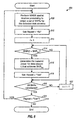
- FIG. 6 is a flow diagram of a process 600 for adjusting the transmit power to achieve a set of post-detection SNRs for the NIMSE receiver.
- Process 600 determines the minimum total transmit power needed to achieve a set of post-detection SNRs that maximize spectral efficiency for the MMSE receiver.
- the MMSE spatial receiver processing is performed on the received symbol streams to obtain a set of post- detection SNRs for the detected data streams (step 608).
- Each post-detection SNR in the set is then examined and the new transmit power, Pi, to use for the corresponding data stream is determined starting at step 614.
- the new transmit power, Pi, for data stream xi that achieves γpost(i) is determined (step 616).
- step 618 Since decreasing the transmit power for data stream xi may increase the post- detection SNR of some other data stream to be higher than r5e"the variable Repeat is set to"Yes" (step 618). This would then result in the re-evaluation of the set of adjusted post-detection SNRs via one more subsequent iteration through the set if the transmit power for any data stream is reduced in the current iteration.
- step 624 a determination is made whether or not Repeat is set to"Yes" (step 624). If the answer is no, indicating that the transmit power was not adjusted for any data stream in the last iteration, then the process terminates. Otherwise, the process returns to step 608 to perform another iteration through the set of post-detection SNRs.
- the transmit powers, ⁇ #i ⁇ , for i D, determined in the prior iteration are used for the MMSE processing.
- the matrices M and D,-'are then updated based on the new composite channel matrix, as shown in equation (18).
- the updated matrices M and D,-'are then used for the MMSE processing of the received symbol streams in step 608.
- the power control process shown in FIG. 6 results in a set of transmit powers, ⁇ Pi ⁇ , for i E D, to be used for the data streams.
- This set includes the transmit powers that have been adjusted to achieve.
- the total power saved may be determined using equation (15).
- the MMSE technique may also be used in conjunction with successive interference cancellation.
- the received vector, y is processed in a recursive manner using MMSE spatial receiver processing to recover one data stream at a time based on a particular detection order.
- the MMSE-SC technique may be implemented using the process shown in FIG. 4 , except that MMSE spatial receiver processing is performed in step 422 instead of CCMI spatial receiver processing.
- the result of the processing shown in FIG. 4 is a set of post-detection SNRs for the detected data streams.
- the post-detection SNR of data stream xi may be expressed as shown in equation (20), which is: ⁇ BR> ⁇ BR> ⁇ BR> ⁇ BR> ⁇ BR> ⁇ BR> V.- ⁇ BR> ⁇ BR> ⁇ BR> 1vit
- the matrix V is different for different stages of the MMSE-SC receiver.
- the post-detection SNR of data stream xi may thus be different depending on the particular stage in which it is recovered.
- the MMSE-SC receiver does not decorrelate the data streams. This is because the underlying MMSE technique used for the spatial receiver processing at each stage does not decorrelate the data streams.
- the post-detection SNR of this data stream may be a function of the transmit powers of all the data streams not yet recovered. Once this data stream has been recovered, its interference effect on the remaining, not yet recovered data streams is estimated and removed. If the interference 020154 27 cancellation is effective, then this data stream has no (or minimal) effect on subsequently recovered data streams, and the transmit power of this data stream does not effect the post-detection SNRs of subsequently recovered data streams.
- adjusting the transmit power of a given data stream xi may affect the post-detection SNRs of the data streams recovered prior to xi but not those recovered after xi (again, if the interference cancellation is effectively performed).
- the transmit powers for the data streams may be adjusted using reverse detection order.
- FIG. 7 is a flow diagram of a process 700 for adjusting the transmit power to achieve a set of post-detection SNRs for the MMSE-SC receiver.
- This set of SNRs may be initially obtained by performing the process shown in FIG. 4 for the MMSE-SC receiver, and may include SNRs that exceed Yset.
- the specific detection order corresponding to the set of post-detection SNRs is obtained (step 710).
- a decrease in the transmit power for any later-recovered data stream may increase the post-detection SNR of the data stream recovered 020154 28 in this stage to be higher than
- a determination is made whether or not there has been a transmit power adjustment for any data stream recovered subsequent to stage k (step 730). If the answer is no, then the process returns to step 714 to evaluate the data stream for the current stage k. Otherwise, if there has been a power adjustment, then the MMSE spatial receiver processing is performed for stage k on the received symbol stream to obtain the post-detection SNR for the data stream detected at stage k (step 732).
- This may be achieved by first determining the data streams that have not yet been recovered at stage k, which are denoted as Dk ⁇ dk,... dNT ⁇ .
- the transmit power originally used for the data stream detected at stage k is then used together with the transmit powers of the data streams detected after stage k (at least one of which has changed) to determine the post-detection SNR for the data stream detected at stage k.
- the composite channel matrix increases for each stage and becomes the original dimension of NR XNT for the first stage.
- the result of the power adjustment in FIG. 7 is a set of transmit powers, ⁇ Pi ⁇ , for i E D, to be used for the data streams.
- This set includes transmit powers that have been adjusted to achieve y,,,.
- the total power saved for the new transmit powers may be determined based on equation (15).
- Another property of the MMSE-SC receiver is that detection order has no effect on spectral efficiency when there is no upper limit on post-detection SNRs (i. e., r,, does not exist).
- varying the detection order will produce different post-detection SNRs for the detected data streams, but the overall spectral efficiency for all data streams will remain the same.
- different detection orders may be associated with different overall spectral efficiencies. In this case, a number of different detection orders may be evaluated to determine the one that provides the best spectral efficiency among the ones evaluated. Alternatively, an exhaustive search may be performed over all possible detection orders to determine the specific detection order that achieves the highest spectral efficiency.
- the process shown in FIG. 5 may also be used to maximize spectral efficiency while minimizing the total required transmit power for the MMSE-SC 020154 29 receiver.
- a list of detection orders to be evaluated may be initially determined (step 512).
- the received symbol streams are initially processed using the MMSE-SC technique and based on that detection order to obtain a set of post-detection SNRs for the detected data streams (step 520).
- Each SNR in the set that is greater than Yset is then adjusted to Yser (step 522), and the transmit power is thereafter adjusted accordingly to achieve the adjusted SNR.
- the post- detection SNR of a given data stream may be a function of the transmit powers of the other data streams when using MMSE processing, an adjustment in the transmit power of one data stream may then cause the post-detection SNRs of the other data streams to change.
- a change in the transmit power of one data stream may only affect the post-detection SNR of a data stream that has been detected earlier. This behavior may be taken into account by using the process shown in FIG. 7 to perform the SNR adjustment. However, these changes in SNRs typically have a marginal effect on the overall spectral efficiency and may be ignored. In any case, the spectral efficiency for each detection order is determined (step 524).
- All detection orders in the list may be evaluated, one at a time, and the set of post-detection SNRs corresponding to the specific detection order that yields the highest spectral efficiency, Pll, ax, is saved (step 528).
- the transmit powers needed to achieve the set of adjusted post-detection SNRs corresponding to p., are then determined (step 534), for example, using the process shown in FIG. 7 .
- a pilot is transmitted along with each data stream to allow the receiver to estimate the post-detection SNR of the data stream.
- the received symbol streams are processed and the post-detection SNRs of the detected data streams reflect the SNRs that would have been achieved if the peak transmit powers are used for the data streams.
- Power control is then performed as described above to determine the minimum transmit powers needed to achieve/ for the detected data streams at the receiver.
- the power adjustments for the data streams would then be indicative of the amount of back-off from the peak transmit power.
- the post-detection SNRs of the detected data streams are reflective of the transmit powers actually used for the data streams.
- the power adjustments for the data streams would then be indicative of the difference (or delta) from the current transmit powers.
- the system described above allows the spectral efficiency to be any real value that does not exceed the p,,,.
- a typical communication system may only support a set of discrete data rates for each data stream.
- the data rate sets may or may not be the same for all data streams. However, for simplicity, one data rate set is assumed to be used for all data streams.
- FIG. 8 shows a plot of spectral efficiency versus post-detection SNR for a communication system that supports a set of discrete data rates. This set of data rates may be converted to a set of discrete spectral efficiencies and is further associated with a set of discrete post-detection SNRs needed to achieve the target FER for a given data stream.
- the discrete spectral efficiencies are labeled as 0,,,, (r) on the vertical axis, where r is used to enumerate through the R discrete data rates (i. e., 1 &1t; r &1t; R).
- the spectral efficiency function for this system is shown by plot 822 (the thick solid, line).
- the highest spectral efficiency is pset (1) and corresponds to Yset (1).
- the discrete operating points at ((ySe, (r), pSe, (r) ), for 15 r &1t;_ R, correspond to the minimum post-detection SNRs necessary to achieve the corresponding spectral efficiencies, and are shown by the solid circles 824.
- the power control techniques described above may also be used for systems that support discrete data rates.
- the objective of the power control is then to determine the transmit power for each data stream that corresponds to the minimum SNR necessary to achieve the operating spectral efficiency.
- New transmit powers may be determined for all data streams that are not operating at the discrete/ (r) points.
- FIG. 8 also shows an example whereby the initial operating points of three data streams, shown by dashed lines 826a through 826c, do not lie on the discrete operating points.
- the transmit power for each of these data streams may be reduced by a backed-off amount, BO (i), for i E D, so that the adjusted post-detection SNR lies on top of r,,,, (r) for the discrete operating point. This then results in the data stream operating at a lower transmit power without incurring a loss in spectral efficiency.
- BO (i) backed-off amount
- the post-detection SNR for data stream x1 may be backed off by BO (1), to achieve , (1) required for spectral efficiency p5et the post-detection SNR for data stream x2 may be backed off by BO (2), to achieve (3) required for spectral efficiency Pse (3), and the post-detection SNR for data stream x3 may be backed off by BO (3), to achieve Yset (4) required for spectral efficiency Pset (4).
- the transmit power of each data stream may be adjusted by the respective backed-off amount, BO (i), without affecting the post-detection SNRs of the other data streams.
- the post-detection SNR of each data stream may be a function of the transmit powers on all data streams, as noted above. This coupling may not allow all of the post-detection SNRs to be adjusted to lie exactly on top of the ideal operating points. In this case, the post- detection SNRs may be adjusted such that they exceed (r) by the smallest amount possible. Again, a number of possible adjustments may be evaluated to determine the best set of backed-off amounts.
- the post-detection SNRs of the data streams may be adjusted in reverse detection order, as described above.
- the post-detection SNR of each data stream may then be adjusted by the backed-off amount, BO (i), to achieve the discrete operating point, except for possibly the first data stream to be recovered.
- the techniques described above may also be adapted to determine the minimum amount of transmit power needed to achieve a specified spectral efficiency.
- the system may be operated in a manner whereby the data rate or spectral efficiency of each user is controlled instead of the transmit power.
- the system may specify a particular data rate and an objective of the transmitter is then to achieve this specified data rate using the minimum amount of transmit power.
- the optimization depends on the specific spatial receiver processing technique used at the receiver as well as the performance of the system's coding and modulation schemes.
- the set of transmit antennas that achieves the maximum spectral efficiency is initially determined based on the assumption that the peak transmit power, Pm", is used for each antenna. This set is denoted as the"optimal"set O.
- the spectral efficiency achieved by a given transmit antenna is dependent on the post- detection SNR achieved by that antenna, which in turn is dependent on the specific receiver processing technique used at the receiver. For a receiver processing technique that employs successive interference cancellation, different detection orders may result in different post-detection SNRs for the transmit antennas. In that case, different detection orders may be evaluated to determine the set of transmit antennas that achieves the maximum spectral efficiency.
- the optimal set O may include less than NT transmit antennas if successive interference 020154 33 cancellation is not used, and typically includes all NT transmit antennas if successive interference cancellation is used. Thus, the optimal set O may include all NT transmit antennas or only a subset of these antennas.
- the specified spectral efficiency is achieved by utilizing the minimum number of transmit antennas.
- the post-detection SNRs of the transmit antennas in set O are first ranked in order from the highest to the lowest post-detection SNR. From the ranked transmit antennas in set O, the minimum number of transmit antennas, jazz needed to achieve the specified spectral efficiency is then determined. This may be achieved by selecting one transmit antenna in set O at a time, starting with the best one having the highest post-detection SNR, and maintaining , a running total of the spectral efficiencies of all selected transmit antennas.
- the set of transmit antennas associated with an aggregate spectral efficiency that is greater than or equal to the specified spectral efficiency is then denoted as the required set R.
- Set R includes Nreq transmit antennas, where Nreq &1t; NT.
- the minimum amount of transmit power required to achieve the specified spectral efficiency is then determined.
- the same back-off is applied uniformly to all Nreq transmit antennas and the same amount of transmit power is used for all Nreq transmit antennas.
- This back-off may be determined in an iterative manner by adjusting the transmit powers for the Nreq transmit antennas either up or down until the specified spectral efficiency is achieved with the minimum amount of transmit power.
- different transmit powers may be used for the N,, q transmit antennas, which may be determined as described above.
- Nreq transmit antennas may be selected for use, and the transmit power for each selected transmit antenna may be adjusted lower.
- Other schemes for determining the minimum amount of transmit power to achieve the specified spectral efficiency may also be implemented, and this is within the scope of the invention.
- the determination of (1) the particular set of transmit antennas to use for data transmission and (2) the amount of transmit power to use for each selected transmit antenna may be made at either the transmitter or receiver. If the determination is made at the receiver, then the transmitter may be provided with control information indicative of the selected transmit antennas and their transmit powers to achieve the specified spectral efficiency.
- the transmit power to be used for the selected transmit antennas may be adjusted correspondingly to achieve the spectral efficiency in the presence of changing link condition.
- the post-detection SNRs of the data streams transmitted on the selected transmit antennas may be determined based on a particular (e. g. , CCMI, CCMI-SC, MMSE, or MMSE-SC) spatial receiver processing technique. Each of the post-detection SNRs may be greater or less than the setpoint, yser (i), needed to achieve the spectral efficiency designated for that transmit antenna.
- the transmit power for each selected transmit antenna may then be adjusted either up or down such that the adjusted post-detection SNR is at or near the setpoint, Yset (i).
- the adjustment may be made such that all selected transmit antennas achieve or exceed their setpoints while minimizing the amount of excess transmit power.
- the power adjustment may also be performed in the aggregate for all selected transmit antennas.
- the receiver may provide power control information to the transmitter to allow the transmitter to adjust the transmit powers for the selected transmit antennas.
- the receiver may provide a power control bit for each selected transmit antenna or one power control bit for all selected transmit antenna.
- Each power control bit may indicate an adjustment of the transmit power either up or down by some predetermined amount.
- Other power control mechanisms may also be employed, and this is within the scope of the invention.
- FIG. 9A is a block diagram of a RX MIMO/data processor 160a capable of implementing the successive cancellation receiver processing technique.
- the transmitted signals from NT transmit antennas are received by each of NR antennas 152a through 152r and routed to a respective receiver 154.
- Each receiver 154 processes a respective received signal and provides a corresponding received symbol stream to RX MIMO/data processor 160a.
- RX MIMO/data processor 160a includes a number of successive (i. e. , cascaded) receiver processing stages 910, one stage for each of the transmitted data streams to be recovered.
- Each receiver processing stage 910 includes a spatial processor 920, an RX data processor 930, and an interference canceller 940, and the last stage 910n includes only spatial processor 920n and RX data processor 930n.
- spatial processor 920a receives and processes the NR received symbol streams (denoted as the vector y) from receivers 154a through 154r based on a particular (e. g. , CCMI or MMSE) receiver processing technique to provide NT detected data streams (denoted as the vector X1).
- a particular e. g. , CCMI or MMSE
- Processor 930a further processes (e. g.
- Spatial processors 920 further provide CSI for the detected data streams, which may be in the form of the post-detection SNRs described above.
- the spatial processor for that stage receives and processes the NR modified symbol streams from the interference canceller in the preceding stage to derive the detected data streams for the stage. Again, one of the detected data streams is selected and processed by the RX data processor to provide a decoded data stream for that stage.
- interference canceller 940a receives the NR received symbol streams from receivers 154 (denoted as the vector yl).
- the interference canceller in that stage receives the NR modified symbol streams from the interference canceller in the preceding stage.
- Each interference canceller also receives the decoded data stream from the RX data processor within the same stage, and performs the processing (e. g., encoding, interleaving, modulation, channel response, and so on) to derive NR remodulated symbol streams (denoted as the vector i) that are estimates of the interference components due to the decoded data stream.
- the remodulated symbol streams are then subtracted from that stage's input symbol streams to derive NR modified symbol streams that include all but the subtracted (i. e. , cancelled) interference components.
- the NR modified symbol streams are then provided to the next stage.
- FIG. 9B is a block diagram of a RX MIMO/data processor 160b that does not implement the successive cancellation receiver processing technique.
- the received symbol streams (denoted as the vector y) are provided to spatial processor 920 and processed based on a particular spatial receiver processing technique to provide the detected data streams (denoted as the vector x).
- RX data processor 930 then receives and processes the detected data streams to provide the decoded data streams.
- Spatial processor 920 further provides CSI for the detected data streams.
- FIG. 10A is a block diagram of an embodiment of a spatial processor 920x, which implements the CCMI technique.
- Spatial processor 920x may be used for each of spatial processors 920a through 920n in FIG. 9A and for spatial processors 920 in FIG. 9B .
- the received or modified symbol streams (denoted as the vector y) are initially filtered by a match filter 1012, which pre- multiplies the vector y with the conjugate-transpose composite channel matrix CH, as shown above in equation (7).
- a multiplier 1014 further pre-multiplies the filtered vector with the inverse square matrix R to form an estimate x of the transmitted vector x, as shown above in equation (10).
- the vector x is provided to a channel estimator 1018 that estimates the channel response matrix H.
- the matrix H may be estimated based on symbols corresponding to pilot data or traffic data or both.
- Channel estimator 1018 then multiplies the channel coefficient matrix H with the diagonal matrix, A, to obtain the composite channel matrix, C.
- Channel estimator 1018 and matrix processor 1020 provide the matrices CH and R-1, respectively, to match filter 1012 and multiplier 1014.
- Spatial processor 920x provides one or more detected data streams to RX data processor 930, which further processes (e. g. , demodulates, de-interleaves, and decodes) each detected data stream to provide a corresponding decoded data stream.
- a CSI processor 1016 determines the CSI for the detected data streams, which may be in the form of the post-detection SNRs determined as shown in equation (12).
- the CSI may be used to determine the transmit power for the data streams.
- FIG. 10B shows an embodiment of a spatial processor 920y, which implements the MMSE technique. Similar to the CCMI technique, the matrices H and An may first be estimated based on the pilot and/or traffic data. The matrices M and D are then determined according to equation (18).
- a multiplier 1022 initially pre-multiplies the received or modified symbol streams (denoted as the vector y) with the matrix M to obtain an initial estimate of the transmitted vector x, as shown in equation (18).
- a multiplier 1024 further pre-multiplies the initial estimate with the diagonal matrix DV1 to form an unbiased estimate x of the transmitted vector x, as also shown in equation (18).
- the unbiased estimate x corresponds to the detected data streams.
- the unbiased estimate x is further provided to an adaptive processor 1026, which derives the matrices M and DV1 based on equation (18).
- Spatial processor 920y provides one or more detected data streams to RX data processor 930 for further processing.
- CSI processor 1016 determines CSI for the detected data streams, which again may be in the form of the post-detection SNRs.
- each spatial processor 920 may be replaced with a space-time processor, which may implement the DFE, MMSE-LE, or MLSE, for a dispersive channel within frequency selective fading.
- the power control may be performed by both the transmitter and receiver systems.
- the receiver system performs the spatial or space-time receiver processing on the received symbol streams to obtain the detected data streams, estimates the post-detection SNRs of the detected data streams, determines the power adjustment for each detected data stream, and provides information indicative of which data stream requires power adjustment.
- the receiver system also provides the power adjustment amount for each data stream that needs adjusting.
- the power adjustment amount is predetermined or fixed (e. g. , 0.5 dB) and need not be reported.
- controller 170 may receive the post-detection SNRs and determine the power adjustment. Controller 170 may then provide the power control information and possibly other information needed by the transmitter system to properly process and transmit the data streams, which are collectively referred to as partial CSI.
- the partial CSI may comprise the post-detection SNRs, the data rates and coding and modulation schemes to be used for the data streams, the power adjustments, and so on, or any combination thereof.
- the partial CSI is then processed by TX data processor 178, modulated by modulator 180, conditioned by transmitters 154, and transmitted via antennas 152.
- the transmitted signals from receiver system'150 are received by antennas 124.
- the received signals are then conditioned by receiver 122, demodulated by demodulator 140, and further processed by RX data processor 142 to recover the reported CSI, which is provided to controller 130.
- Controller 130 then provides various controls used to process (e. g. , code and modulate) the data streams and adjust the transmit powers for these data streams.
- the techniques described herein for controlling transmit power may be used for various multi-channel communication systems, including MIMO systems, OFDM systems, MIMO-OFDM systems, and so on. These techniques may be advantageously used for systems having a particular maximum allowed spectral efficiency, Pset X (as illustrated in FIG. 2 ) and for systems supporting one or more sets of discrete data rates for the data streams (as illustrated in FIG. 8 ).
- the techniques described herein may also be used to control transmit power for each data stream, which may be transmitted on one or more transmission channels.
- Each data stream may be associated with a particular data rate and a particular coding and modulation scheme.
- each data stream may be associated with a different receiver.
- the power control is specifically described for the CCMI, CCMI- SC, MMSE, and MMSE-SC receiver processing techniques.
- the power control techniques described herein may also be used for other receiver processing techniques, 020154 39 and this is within the scope of the invention.
- these power control techniques may be used in conjunction with space-time receiver processing techniques.
- the power control techniques described herein may be implemented by various means. For example, these techniques may be implemented in hardware, software, or a combination thereof.
- the elements used to control transmit power for the data streams may be implemented within one or more application specific integrated circuits (ASICs), digital signal processors (DSPs), digital signal processing devices (DSPDs), programmable logic devices (PLDs), field programmable gate arrays (FPGAs), processors, controllers, micro-controllers, microprocessors, other electronic units designed to perform the functions described herein, or a combination thereof.
- ASICs application specific integrated circuits
- DSPs digital signal processors
- DSPDs digital signal processing devices
- PLDs programmable logic devices
- FPGAs field programmable gate arrays
- processors controllers, micro-controllers, microprocessors, other electronic units designed to perform the functions described herein, or a combination thereof.
- the power control may be implemented with modules (e. g. , procedures, functions, and so on) that perform the functions described herein.
- the software codes may be stored in a memory unit (e. g. , memory 132 and/or 172 in FIG. 1 ) and executed by a processor (e. g. , controller 130 and/or 170).
- the memory unit may be implemented within the processor or external to the processor, in which case it can be communicatively coupled to the processor via various means as is known in the art.
Landscapes
- Engineering & Computer Science (AREA)
- Computer Networks & Wireless Communication (AREA)
- Signal Processing (AREA)
- Quality & Reliability (AREA)
- Radio Transmission System (AREA)
- Mobile Radio Communication Systems (AREA)
- Transmitters (AREA)
- Cable Transmission Systems, Equalization Of Radio And Reduction Of Echo (AREA)
- Data Exchanges In Wide-Area Networks (AREA)
Priority Applications (1)
| Application Number | Priority Date | Filing Date | Title |
|---|---|---|---|
| EP10173988A EP2259443A3 (fr) | 2002-02-19 | 2003-02-19 | Commande de puissance pour des systèmes à entrées multiples sorties multiples avec d'informations concernant l'etat du canal partielles (CSI) |
Applications Claiming Priority (2)
| Application Number | Priority Date | Filing Date | Title |
|---|---|---|---|
| US10/079,970 US7076263B2 (en) | 2002-02-19 | 2002-02-19 | Power control for partial channel-state information (CSI) multiple-input, multiple-output (MIMO) systems |
| EP03709263A EP1476958B1 (fr) | 2002-02-19 | 2003-02-19 | Commande de puissance pour de multiples saisies d'informations concernant l'etat du canal partielles (csi), systemes de multiples sorties (mimo) |
Related Parent Applications (2)
| Application Number | Title | Priority Date | Filing Date |
|---|---|---|---|
| EP03709263A Division EP1476958B1 (fr) | 2002-02-19 | 2003-02-19 | Commande de puissance pour de multiples saisies d'informations concernant l'etat du canal partielles (csi), systemes de multiples sorties (mimo) |
| EP03709263.2 Division | 2003-02-19 |
Related Child Applications (1)
| Application Number | Title | Priority Date | Filing Date |
|---|---|---|---|
| EP10173988.6 Division-Into | 2010-08-25 |
Publications (2)
| Publication Number | Publication Date |
|---|---|
| EP1973237A2 true EP1973237A2 (fr) | 2008-09-24 |
| EP1973237A3 EP1973237A3 (fr) | 2011-02-23 |
Family
ID=27733118
Family Applications (3)
| Application Number | Title | Priority Date | Filing Date |
|---|---|---|---|
| EP03709263A Expired - Lifetime EP1476958B1 (fr) | 2002-02-19 | 2003-02-19 | Commande de puissance pour de multiples saisies d'informations concernant l'etat du canal partielles (csi), systemes de multiples sorties (mimo) |
| EP08012143A Withdrawn EP1973237A3 (fr) | 2002-02-19 | 2003-02-19 | Contrôle d'alimentation pour des systèmes d'entrées multiples d'informations sur l'état du canal partiel (CSI), et de sortie multiples (MIMO) |
| EP10173988A Withdrawn EP2259443A3 (fr) | 2002-02-19 | 2003-02-19 | Commande de puissance pour des systèmes à entrées multiples sorties multiples avec d'informations concernant l'etat du canal partielles (CSI) |
Family Applications Before (1)
| Application Number | Title | Priority Date | Filing Date |
|---|---|---|---|
| EP03709263A Expired - Lifetime EP1476958B1 (fr) | 2002-02-19 | 2003-02-19 | Commande de puissance pour de multiples saisies d'informations concernant l'etat du canal partielles (csi), systemes de multiples sorties (mimo) |
Family Applications After (1)
| Application Number | Title | Priority Date | Filing Date |
|---|---|---|---|
| EP10173988A Withdrawn EP2259443A3 (fr) | 2002-02-19 | 2003-02-19 | Commande de puissance pour des systèmes à entrées multiples sorties multiples avec d'informations concernant l'etat du canal partielles (CSI) |
Country Status (14)
| Country | Link |
|---|---|
| US (2) | US7076263B2 (fr) |
| EP (3) | EP1476958B1 (fr) |
| JP (2) | JP4401784B2 (fr) |
| KR (1) | KR101070586B1 (fr) |
| CN (2) | CN101123461B (fr) |
| AT (1) | ATE400931T1 (fr) |
| AU (1) | AU2003213217A1 (fr) |
| BR (1) | BR0307762A (fr) |
| CA (1) | CA2475515A1 (fr) |
| DE (1) | DE60322025D1 (fr) |
| ES (1) | ES2309303T3 (fr) |
| MX (1) | MXPA04008007A (fr) |
| TW (1) | TWI311015B (fr) |
| WO (1) | WO2003071711A2 (fr) |
Families Citing this family (134)
| Publication number | Priority date | Publication date | Assignee | Title |
|---|---|---|---|---|
| US7952511B1 (en) | 1999-04-07 | 2011-05-31 | Geer James L | Method and apparatus for the detection of objects using electromagnetic wave attenuation patterns |
| US8249187B2 (en) | 2002-05-09 | 2012-08-21 | Google Inc. | System, method and apparatus for mobile transmit diversity using symmetric phase difference |
| US7020110B2 (en) * | 2002-01-08 | 2006-03-28 | Qualcomm Incorporated | Resource allocation for MIMO-OFDM communication systems |
| US7076263B2 (en) * | 2002-02-19 | 2006-07-11 | Qualcomm, Incorporated | Power control for partial channel-state information (CSI) multiple-input, multiple-output (MIMO) systems |
| US6862456B2 (en) * | 2002-03-01 | 2005-03-01 | Cognio, Inc. | Systems and methods for improving range for multicast wireless communication |
| WO2003075471A2 (fr) * | 2002-03-01 | 2003-09-12 | Cognio, Inc. | Systeme et procede de combinaison conjointe du rapport maximal par traitement de signaux fonde sur le domaine temporel |
| US6687492B1 (en) * | 2002-03-01 | 2004-02-03 | Cognio, Inc. | System and method for antenna diversity using joint maximal ratio combining |
| US6785520B2 (en) * | 2002-03-01 | 2004-08-31 | Cognio, Inc. | System and method for antenna diversity using equal power joint maximal ratio combining |
| KR100464014B1 (ko) * | 2002-03-21 | 2004-12-30 | 엘지전자 주식회사 | 다중 입출력 이동 통신 시스템에서의 폐루프 신호 처리 방법 |
| US6871049B2 (en) | 2002-03-21 | 2005-03-22 | Cognio, Inc. | Improving the efficiency of power amplifiers in devices using transmit beamforming |
| US7006804B1 (en) * | 2002-07-10 | 2006-02-28 | At&T Corp. | High-speed two-way point-to-point transmission |
| US8194770B2 (en) | 2002-08-27 | 2012-06-05 | Qualcomm Incorporated | Coded MIMO systems with selective channel inversion applied per eigenmode |
| US7002900B2 (en) | 2002-10-25 | 2006-02-21 | Qualcomm Incorporated | Transmit diversity processing for a multi-antenna communication system |
| US8208364B2 (en) | 2002-10-25 | 2012-06-26 | Qualcomm Incorporated | MIMO system with multiple spatial multiplexing modes |
| US20040081131A1 (en) | 2002-10-25 | 2004-04-29 | Walton Jay Rod | OFDM communication system with multiple OFDM symbol sizes |
| US7986742B2 (en) | 2002-10-25 | 2011-07-26 | Qualcomm Incorporated | Pilots for MIMO communication system |
| US8218609B2 (en) | 2002-10-25 | 2012-07-10 | Qualcomm Incorporated | Closed-loop rate control for a multi-channel communication system |
| US8570988B2 (en) | 2002-10-25 | 2013-10-29 | Qualcomm Incorporated | Channel calibration for a time division duplexed communication system |
| US8169944B2 (en) | 2002-10-25 | 2012-05-01 | Qualcomm Incorporated | Random access for wireless multiple-access communication systems |
| US8320301B2 (en) | 2002-10-25 | 2012-11-27 | Qualcomm Incorporated | MIMO WLAN system |
| US8134976B2 (en) | 2002-10-25 | 2012-03-13 | Qualcomm Incorporated | Channel calibration for a time division duplexed communication system |
| US7324429B2 (en) | 2002-10-25 | 2008-01-29 | Qualcomm, Incorporated | Multi-mode terminal in a wireless MIMO system |
| US8170513B2 (en) | 2002-10-25 | 2012-05-01 | Qualcomm Incorporated | Data detection and demodulation for wireless communication systems |
| US7386057B2 (en) * | 2003-02-20 | 2008-06-10 | Nec Corporation | Iterative soft interference cancellation and filtering for spectrally efficient high-speed transmission in MIMO systems |
| US7231251B2 (en) * | 2003-08-14 | 2007-06-12 | Cardiac Pacemakers, Inc. | EMI detection for implantable medical devices |
| US7724838B2 (en) | 2003-09-25 | 2010-05-25 | Qualcomm Incorporated | Hierarchical coding with multiple antennas in a wireless communication system |
| KR100713403B1 (ko) * | 2003-09-30 | 2007-05-04 | 삼성전자주식회사 | 통신 시스템에서 채널 상태에 따른 송신 방식 제어 장치및 방법 |
| US7508748B2 (en) * | 2003-10-24 | 2009-03-24 | Qualcomm Incorporated | Rate selection for a multi-carrier MIMO system |
| US7437135B2 (en) | 2003-10-30 | 2008-10-14 | Interdigital Technology Corporation | Joint channel equalizer interference canceller advanced receiver |
| US7616698B2 (en) | 2003-11-04 | 2009-11-10 | Atheros Communications, Inc. | Multiple-input multiple output system and method |
| KR101015736B1 (ko) * | 2003-11-19 | 2011-02-22 | 삼성전자주식회사 | 직교 주파수 분할 다중 방식의 이동통신 시스템에서선택적 전력 제어 장치 및 방법 |
| US7164740B2 (en) * | 2003-11-21 | 2007-01-16 | Interdigital Technology Corporation | Wireless communication apparatus using fast fourier transforms to create, optimize and incorporate a beam space antenna array in an orthogonal frequency division multiplexing receiver |
| US9473269B2 (en) | 2003-12-01 | 2016-10-18 | Qualcomm Incorporated | Method and apparatus for providing an efficient control channel structure in a wireless communication system |
| US7430430B2 (en) * | 2003-12-16 | 2008-09-30 | Magnolia Broadband Inc. | Adjusting a signal at a diversity system |
| US7302009B2 (en) | 2003-12-17 | 2007-11-27 | Qualcomm Incorporated | Broadcast transmission with spatial spreading in a multi-antenna communication system |
| US8204149B2 (en) | 2003-12-17 | 2012-06-19 | Qualcomm Incorporated | Spatial spreading in a multi-antenna communication system |
| US8249518B2 (en) * | 2003-12-29 | 2012-08-21 | Telefonaktiebolaget Lm Ericsson (Publ) | Network controlled feedback for MIMO systems |
| CN100372257C (zh) * | 2003-12-31 | 2008-02-27 | 中国科学技术大学 | 多天线系统中基于信号干扰比的功率控制方法 |
| US7336746B2 (en) | 2004-12-09 | 2008-02-26 | Qualcomm Incorporated | Data transmission with spatial spreading in a MIMO communication system |
| TW200629772A (en) * | 2004-01-14 | 2006-08-16 | Interdigital Tech Corp | Method and apparatus for dynamically selecting the best antennas/mode ports for transmission and reception |
| US7400692B2 (en) | 2004-01-14 | 2008-07-15 | Interdigital Technology Corporation | Telescoping window based equalization |
| US7430190B2 (en) * | 2004-01-22 | 2008-09-30 | The Regents Of The University Of California | Systems and methods for resource allocation to multiple antenna arrays for maintaining a constant bit rate (CBR) channel |
| US8169889B2 (en) | 2004-02-18 | 2012-05-01 | Qualcomm Incorporated | Transmit diversity and spatial spreading for an OFDM-based multi-antenna communication system |
| US7408975B2 (en) * | 2004-03-10 | 2008-08-05 | New Jersey Institute Of Technology | Transmit power adaptation for CDMA communication systems using successive interference cancellation |
| US7720042B2 (en) | 2004-04-02 | 2010-05-18 | Lg Electronics Inc. | Method for transmitting and receiving data signal in MIMO system |
| WO2005099124A1 (fr) * | 2004-04-07 | 2005-10-20 | Lg Electronics Inc. | Procede d'emission et de reception de signal de donnees dans un systeme mimo |
| KR100724989B1 (ko) * | 2004-04-14 | 2007-06-04 | 삼성전자주식회사 | 직교 주파수 분할 다중 접속 방식을 사용하는 통신시스템에서 전력 제어 장치 및 방법 |
| US8923785B2 (en) | 2004-05-07 | 2014-12-30 | Qualcomm Incorporated | Continuous beamforming for a MIMO-OFDM system |
| US7620096B2 (en) * | 2004-05-25 | 2009-11-17 | New Jersey Institute Of Technology | Equal BER power control for uplink MC-CDMA with MMSE successive interference cancellation |
| US20060029148A1 (en) * | 2004-08-06 | 2006-02-09 | Tsatsanis Michail K | Method and apparatus for training using variable transmit signal power levels |
| US7894548B2 (en) | 2004-09-03 | 2011-02-22 | Qualcomm Incorporated | Spatial spreading with space-time and space-frequency transmit diversity schemes for a wireless communication system |
| US7656842B2 (en) * | 2004-09-30 | 2010-02-02 | Motorola, Inc. | Method and apparatus for MIMO transmission optimized for successive cancellation receivers |
| JP4720178B2 (ja) * | 2004-12-22 | 2011-07-13 | 日本電気株式会社 | 通信システム及びそれに用いる送受信機 |
| US7747271B2 (en) * | 2005-03-02 | 2010-06-29 | Qualcomm Incorporated | Radiated power control for a multi-antenna transmission |
| WO2006093468A1 (fr) * | 2005-03-04 | 2006-09-08 | Matsushita Electric Industrial Co., Ltd. | Attribution de puissance d'emission dans un systeme de communication sans fil |
| US8515359B2 (en) * | 2005-03-09 | 2013-08-20 | Intel Corporation | Method and apparatus to provide low cost transmit beamforming for network devices |
| KR100922958B1 (ko) * | 2005-03-14 | 2009-10-22 | 삼성전자주식회사 | 다중 사용자 다이버시티를 지원하는 다중 안테나 이동통신시스템에서 사용자 할당장치 및 방법 |
| US7466749B2 (en) | 2005-05-12 | 2008-12-16 | Qualcomm Incorporated | Rate selection with margin sharing |
| RU2007144717A (ru) * | 2005-06-01 | 2009-06-10 | Мацусита Электрик Индастриал Ко., Лтд. (Jp) | Передающее устройство, приемное устройство и способ управления мощностью передачи |
| US8971461B2 (en) | 2005-06-01 | 2015-03-03 | Qualcomm Incorporated | CQI and rank prediction for list sphere decoding and ML MIMO receivers |
| US7715863B2 (en) * | 2005-06-01 | 2010-05-11 | Nec Laboratories America, Inc. | Throughput maximization using quantized rate control in multiple antenna communication |
| US7583766B2 (en) * | 2005-06-10 | 2009-09-01 | Nokia Corporation | System, and associated method, for utilizing block BLAST with PPIC in a MIMO multicode MC-CDMA system |
| US7630732B2 (en) * | 2005-06-14 | 2009-12-08 | Interdigital Technology Corporation | Method and apparatus for generating feedback information for transmit power control in a multiple-input multiple-output wireless communication system |
| US20060285531A1 (en) * | 2005-06-16 | 2006-12-21 | Howard Steven J | Efficient filter weight computation for a MIMO system |
| US8358714B2 (en) | 2005-06-16 | 2013-01-22 | Qualcomm Incorporated | Coding and modulation for multiple data streams in a communication system |
| AU2006270663B2 (en) | 2005-07-18 | 2009-10-29 | Samsung Electronics Co., Ltd. | Apparatus and method for transmitting and receiving a reverse channel in a mobile communication system for packet data |
| US20070111681A1 (en) * | 2005-11-14 | 2007-05-17 | Alberth William P Jr | Transmit power allocation in wireless communication devices |
| US8064835B2 (en) * | 2006-01-11 | 2011-11-22 | Quantenna Communications, Inc. | Antenna assignment system and method |
| KR100922936B1 (ko) * | 2006-02-07 | 2009-10-22 | 삼성전자주식회사 | 통신 시스템에서 데이터 송수신 방법 및 시스템 |
| US7440412B2 (en) * | 2006-03-13 | 2008-10-21 | Tzero Technologies, Inc. | Link quality prediction |
| US7804800B2 (en) * | 2006-03-31 | 2010-09-28 | Intel Corporation | Efficient training schemes for MIMO based wireless networks |
| US7936847B2 (en) * | 2006-04-11 | 2011-05-03 | The Mitre Corporation | Removal of matched waveform interference |
| US8543070B2 (en) | 2006-04-24 | 2013-09-24 | Qualcomm Incorporated | Reduced complexity beam-steered MIMO OFDM system |
| TWI411255B (zh) * | 2006-05-04 | 2013-10-01 | Quantenna Communications Inc | 多天線接收器系統及方法 |
| US8091012B2 (en) * | 2006-05-04 | 2012-01-03 | Quantenna Communications Inc. | System and method for decreasing decoder complexity |
| US8170604B2 (en) * | 2006-06-27 | 2012-05-01 | Motorola Mobility, Inc. | Method and system for managing communications for a multi-mode communications device |
| US8923267B2 (en) * | 2006-06-30 | 2014-12-30 | Qualcomm Incorporated | System and method for high speed peer-to-peer connectivity between wireless devices |
| WO2008029845A1 (fr) * | 2006-09-06 | 2008-03-13 | Sharp Kabushiki Kaisha | Dispositif, système et procédé de réception/transmission |
| US7751495B1 (en) * | 2006-09-06 | 2010-07-06 | Marvell International Ltd. | Equal power output spatial spreading matrix for use in a wireless MIMO communication system |
| US8626104B2 (en) * | 2006-09-28 | 2014-01-07 | Apple Inc. | Generalized codebook design method for limited feedback systems |
| US8063839B2 (en) * | 2006-10-17 | 2011-11-22 | Quantenna Communications, Inc. | Tunable antenna system |
| US8059702B2 (en) * | 2006-11-30 | 2011-11-15 | Motorola Mobility, Inc. | Monitoring multiple modem transmission in a communication device |
| US8665778B2 (en) * | 2006-11-30 | 2014-03-04 | Motorola Mobility Llc | Monitoring and control of transmit power in a multi-modem wireless communication device |
| US7924951B2 (en) * | 2006-12-14 | 2011-04-12 | The Trustees Of Columbia University In The City Of New York | Methods and systems for digital wireless communication |
| US8744519B2 (en) * | 2006-12-14 | 2014-06-03 | Motorola Mobility Llc | Multimodal phone data session management enhancement that alleviates dual transmission problems |
| US7965803B2 (en) * | 2006-12-14 | 2011-06-21 | The Trustees Of Columbia University In The City Of New York | Methods and systems for providing feedback for beamforming |
| US7693238B1 (en) * | 2007-01-08 | 2010-04-06 | Hellosoft India PVT. Ltd | Method and system for V-BLAST detection with near maximum likelihood performance and low complexity |
| JP2008245017A (ja) * | 2007-03-28 | 2008-10-09 | Nec Corp | 無線基地局装置、リソース割当て方法、リソース割当てプログラム |
| US7890059B2 (en) * | 2007-05-01 | 2011-02-15 | Broadcom Corporation | Successive interference cancellation in code division multiple access system using variable interferer weights |
| US8537922B2 (en) * | 2007-06-19 | 2013-09-17 | The Trustees Of Columbia University In The City Of New York | Methods and systems for providing feedback for beamforming and power control |
| CN101779390B (zh) * | 2007-06-29 | 2013-01-02 | Lg电子株式会社 | 广播接收系统和处理广播信号的方法 |
| KR20090001402A (ko) * | 2007-06-29 | 2009-01-08 | 엘지전자 주식회사 | 방송 수신이 가능한 텔레매틱스 단말기 및 방송 신호 처리방법 |
| US7864121B2 (en) * | 2007-07-06 | 2011-01-04 | Qualcomm Incorporated | MIMO self-expandable antenna structure |
| US8213344B2 (en) * | 2007-08-07 | 2012-07-03 | Intel Corporation | Method and apparatus for antenna allocation on a multi-radio platform |
| US8213979B1 (en) * | 2007-08-15 | 2012-07-03 | Sprint Spectrum L.P. | Method and system for forward link and/or reverse link power control |
| WO2009054938A1 (fr) * | 2007-10-19 | 2009-04-30 | Quantenna Communications, Inc. | Limitation d'interférence dans un système de communication codée |
| US20090122854A1 (en) * | 2007-11-14 | 2009-05-14 | The Hong Kong University Of Science And Technology | Frequency domain equalization with transmit precoding for high speed data transmission |
| US8457549B2 (en) * | 2008-02-29 | 2013-06-04 | Lingna Holdings Pte., Llc | Multi-user MIMO relay protocol with self-interference cancellation |
| JP4607982B2 (ja) * | 2008-03-28 | 2011-01-05 | 日本電信電話株式会社 | 無線送信方法、基地局装置、無線通信方法、及び無線通信システム |
| US8195250B2 (en) * | 2008-04-30 | 2012-06-05 | Motorola Mobility, Inc. | Method and apparatus for controlling power among modems in a multi-mode mobile communication device |
| JP4955614B2 (ja) * | 2008-06-25 | 2012-06-20 | 京セラ株式会社 | 無線通信装置および無線通信方法 |
| WO2010003176A1 (fr) * | 2008-07-07 | 2010-01-14 | Commonwealth Scientific And Industrial Resaerch Organisation | Transmission de paquet en parallèle |
| WO2010005988A2 (fr) * | 2008-07-07 | 2010-01-14 | Zte U.S.A., Inc. | Procédé et système de commande de puissance espace-temps pour transmissions mimo |
| US20110077044A1 (en) * | 2008-08-20 | 2011-03-31 | Qualcomm Incorporated | Power control for wireless lan stations |
| US9031044B2 (en) | 2008-08-20 | 2015-05-12 | Qualcomm Incorporated | Power control for wireless LAN stations |
| US8358631B2 (en) * | 2008-09-04 | 2013-01-22 | Telefonaktiebolaget L M Ericsson (Publ) | Beamforming systems and method |
| US8738063B1 (en) | 2008-10-24 | 2014-05-27 | Sprint Communications Company L.P. | Power control based on multi-antenna mode distribution |
| US8364193B1 (en) | 2009-05-04 | 2013-01-29 | Sprint Communications Company L.P. | Forward link power control |
| CN102025454B (zh) * | 2009-09-18 | 2013-04-17 | 富士通株式会社 | 预编码矩阵码本的生成方法及装置 |
| CN102104948A (zh) * | 2009-12-17 | 2011-06-22 | 上海电机学院 | 分布式多输入多输出系统中的下行传输方法及装置 |
| US20110194430A1 (en) * | 2009-12-18 | 2011-08-11 | Qualcomm Incorporated | Method and apparatus for unified channel estimation for wireless communication |
| US9887858B2 (en) | 2010-01-08 | 2018-02-06 | Nokia Solutions And Networks Oy | Method and apparatus for using demodulation reference signal multiplexing in wireless communication |
| JP5586043B2 (ja) * | 2010-01-12 | 2014-09-10 | 独立行政法人情報通信研究機構 | Mimo−ofdmシステムにおける電力割り当て方法,及び電力割り当て装置 |
| WO2011138979A1 (fr) * | 2010-05-03 | 2011-11-10 | Pantech Co., Ltd. | Procédé destiné à un procédé de données de voie de retour et de réception, récepteur et émetteur correspondants dans un système de télécommunication sans fil |
| FR2961050B1 (fr) * | 2010-06-04 | 2012-07-20 | Commissariat Energie Atomique | Methode d'ordonnancement a economie d'energie |
| KR101681094B1 (ko) | 2010-06-29 | 2016-12-01 | 삼성전자주식회사 | 무선 네트워크에서의 송신 전력 제어 방법 및 장치 |
| US8934499B1 (en) | 2011-02-25 | 2015-01-13 | Sprint Communications Company L.P. | Dynamically transferring between multiple-input and multiple-output (MIMO) transmit modes based on a usage level of a wireless access node |
| US8526380B1 (en) | 2011-03-17 | 2013-09-03 | Sprint Communications Company L.P. | Dynamic transmission mode selection based on wireless communication device data rate capabilities |
| US8972815B1 (en) * | 2012-03-20 | 2015-03-03 | Xilinx, Inc. | Recovery of media datagrams |
| CN103369657B (zh) * | 2012-04-06 | 2017-05-24 | 中兴通讯股份有限公司 | 一种功率分配方法和通信节点 |
| CN103369647B (zh) * | 2012-04-06 | 2017-12-12 | 中兴通讯股份有限公司 | 多天线的功率分配方法及装置 |
| KR20130114471A (ko) * | 2012-04-09 | 2013-10-17 | 한국전자통신연구원 | 다중입력 다중출력 시스템에서 송신 전력을 할당하는 방법 및 장치 |
| US9287953B2 (en) | 2012-05-21 | 2016-03-15 | Qualcomm Incorporated | Systems, apparatus, and methods for antenna selection |
| US8942772B2 (en) | 2012-05-21 | 2015-01-27 | Qualcomm Incorporated | Systems, apparatus, and methods for arbitration of antenna switch configuration among different clients |
| US9503170B2 (en) | 2012-06-04 | 2016-11-22 | Trustees Of Tufts College | System, method and apparatus for multi-input multi-output communications over per-transmitter power-constrained channels |
| EP2893756A1 (fr) * | 2012-09-05 | 2015-07-15 | Telefonaktiebolaget L M Ericsson (Publ) | Commande automatique de puissance d'émission en configuration mimo nxn los pour applications sans fil |
| US9832623B2 (en) * | 2012-12-05 | 2017-11-28 | T-Mobile Usa, Inc. | Energy-efficient push/poll notification service |
| JP5901868B1 (ja) | 2015-08-05 | 2016-04-13 | 三菱電機株式会社 | 無線送信装置 |
| US9794879B1 (en) * | 2016-12-23 | 2017-10-17 | Intel IP Corporation | Power saving mechanism for MU-MIMO transmissions |
| WO2018177562A1 (fr) * | 2017-04-01 | 2018-10-04 | Telefonaktiebolaget Lm Ericsson (Publ) | Commande de puissance d'émission adaptative améliorée pour système mimo de ligne de visée |
| US11138076B2 (en) * | 2017-06-30 | 2021-10-05 | Redis Ltd. | Methods, systems, and media for controlling append-only file rewrites |
| US10715233B2 (en) * | 2017-08-31 | 2020-07-14 | Qualcomm Incorporated | Sounding reference signal (SRS) transmit antenna selection |
| US11381284B2 (en) | 2020-06-18 | 2022-07-05 | Samsung Electronics Co., Ltd. | Access point supporting wireless communication and operation method thereof |
| EP4500709A4 (fr) * | 2022-03-28 | 2026-01-21 | Ericsson Telefon Ab L M | Reconfiguration de la liaison radio micro-ondes los-mimo pour un nombre variable de flux de données mimo |
Citations (3)
| Publication number | Priority date | Publication date | Assignee | Title |
|---|---|---|---|---|
| US20020191703A1 (en) | 2001-03-23 | 2002-12-19 | Fuyun Ling | Method and apparatus for utilizing channel state information in a wireless communication system |
| US20030035491A1 (en) | 2001-05-11 | 2003-02-20 | Walton Jay R. | Method and apparatus for processing data in a multiple-input multiple-output (MIMO) communication system utilizing channel state information |
| US20030125040A1 (en) | 2001-11-06 | 2003-07-03 | Walton Jay R. | Multiple-access multiple-input multiple-output (MIMO) communication system |
Family Cites Families (24)
| Publication number | Priority date | Publication date | Assignee | Title |
|---|---|---|---|---|
| KR0155818B1 (ko) * | 1995-04-29 | 1998-11-16 | 김광호 | 다중 반송파 전송시스템에서 적응형 전력 분배 방법 및 장치 |
| US7929498B2 (en) * | 1995-06-30 | 2011-04-19 | Interdigital Technology Corporation | Adaptive forward power control and adaptive reverse power control for spread-spectrum communications |
| US5924015A (en) | 1996-04-30 | 1999-07-13 | Trw Inc | Power control method and apparatus for satellite based telecommunications system |
| CA2302289C (fr) | 1996-08-29 | 2005-11-08 | Gregory G. Raleigh | Traitement spatio-temporel pour telecommunications |
| US5886988A (en) * | 1996-10-23 | 1999-03-23 | Arraycomm, Inc. | Channel assignment and call admission control for spatial division multiple access communication systems |
| US6084915A (en) * | 1997-03-03 | 2000-07-04 | 3Com Corporation | Signaling method having mixed-base shell map indices |
| FI102703B1 (fi) * | 1997-03-27 | 1999-01-29 | Nokia Telecommunications Oy | Kanavan allokointimenetelmä |
| US6308080B1 (en) * | 1997-05-16 | 2001-10-23 | Texas Instruments Incorporated | Power control in point-to-multipoint systems |
| EP0899896A1 (fr) * | 1997-08-27 | 1999-03-03 | Siemens Aktiengesellschaft | Procédé et dispositif d'estimation de paramètres spatiaux de canaux de transmission |
| US6608874B1 (en) * | 1998-01-12 | 2003-08-19 | Hughes Electronics Corporation | Method and apparatus for quadrature multi-pulse modulation of data for spectrally efficient communication |
| EP0930752A3 (fr) * | 1998-01-14 | 1999-10-20 | Motorola, Inc. | Procédé d'allocation de données et de pouvoir dans un système de communcication multiporteur |
| FI108588B (fi) * | 1998-12-15 | 2002-02-15 | Nokia Corp | Menetelmä ja radiojärjestelmä digitaalisen signaalin siirtoon |
| EP1075093A1 (fr) * | 1999-08-02 | 2001-02-07 | Interuniversitair Micro-Elektronica Centrum Vzw | Procédé et dispositif pour une transmission multi-utilisateurs |
| JP2001244879A (ja) * | 2000-03-02 | 2001-09-07 | Matsushita Electric Ind Co Ltd | 送信電力制御装置及びその方法 |
| US6963546B2 (en) * | 2000-03-15 | 2005-11-08 | Interdigital Technology Corp. | Multi-user detection using an adaptive combination of joint detection and successive interface cancellation |
| US6473467B1 (en) | 2000-03-22 | 2002-10-29 | Qualcomm Incorporated | Method and apparatus for measuring reporting channel state information in a high efficiency, high performance communications system |
| CN1140147C (zh) * | 2000-07-01 | 2004-02-25 | 信息产业部电信传输研究所 | 一种外环功率控制的方法和系统 |
| FI109393B (fi) * | 2000-07-14 | 2002-07-15 | Nokia Corp | Menetelmä mediavirran enkoodaamiseksi skaalautuvasti, skaalautuva enkooderi ja päätelaite |
| US6996380B2 (en) * | 2001-07-26 | 2006-02-07 | Ericsson Inc. | Communication system employing transmit macro-diversity |
| US7133070B2 (en) * | 2001-09-20 | 2006-11-07 | Eastman Kodak Company | System and method for deciding when to correct image-specific defects based on camera, scene, display and demographic data |
| US7349667B2 (en) * | 2001-10-19 | 2008-03-25 | Texas Instruments Incorporated | Simplified noise estimation and/or beamforming for wireless communications |
| US8018903B2 (en) * | 2001-11-21 | 2011-09-13 | Texas Instruments Incorporated | Closed-loop transmit diversity scheme in frequency selective multipath channels |
| US7346126B2 (en) * | 2001-11-28 | 2008-03-18 | Telefonaktiebolaget L M Ericsson (Publ) | Method and apparatus for channel estimation using plural channels |
| US7076263B2 (en) * | 2002-02-19 | 2006-07-11 | Qualcomm, Incorporated | Power control for partial channel-state information (CSI) multiple-input, multiple-output (MIMO) systems |
-
2002
- 2002-02-19 US US10/079,970 patent/US7076263B2/en not_active Expired - Lifetime
-
2003
- 2003-02-19 TW TW092103402A patent/TWI311015B/zh not_active IP Right Cessation
- 2003-02-19 CN CN2007101422015A patent/CN101123461B/zh not_active Expired - Lifetime
- 2003-02-19 CA CA002475515A patent/CA2475515A1/fr not_active Abandoned
- 2003-02-19 BR BRPI0307762-4A patent/BR0307762A/pt not_active IP Right Cessation
- 2003-02-19 AT AT03709263T patent/ATE400931T1/de not_active IP Right Cessation
- 2003-02-19 EP EP03709263A patent/EP1476958B1/fr not_active Expired - Lifetime
- 2003-02-19 WO PCT/US2003/005371 patent/WO2003071711A2/fr not_active Ceased
- 2003-02-19 AU AU2003213217A patent/AU2003213217A1/en not_active Abandoned
- 2003-02-19 ES ES03709263T patent/ES2309303T3/es not_active Expired - Lifetime
- 2003-02-19 KR KR1020047012605A patent/KR101070586B1/ko not_active Expired - Fee Related
- 2003-02-19 CN CNB038083779A patent/CN100448177C/zh not_active Expired - Lifetime
- 2003-02-19 EP EP08012143A patent/EP1973237A3/fr not_active Withdrawn
- 2003-02-19 DE DE60322025T patent/DE60322025D1/de not_active Expired - Lifetime
- 2003-02-19 EP EP10173988A patent/EP2259443A3/fr not_active Withdrawn
- 2003-02-19 MX MXPA04008007A patent/MXPA04008007A/es active IP Right Grant
- 2003-02-19 JP JP2003570494A patent/JP4401784B2/ja not_active Expired - Lifetime
-
2005
- 2005-02-01 US US11/049,319 patent/US7221956B2/en not_active Expired - Lifetime
-
2009
- 2009-04-28 JP JP2009108682A patent/JP2009239917A/ja active Pending
Patent Citations (4)
| Publication number | Priority date | Publication date | Assignee | Title |
|---|---|---|---|---|
| US20020191703A1 (en) | 2001-03-23 | 2002-12-19 | Fuyun Ling | Method and apparatus for utilizing channel state information in a wireless communication system |
| US20030003880A1 (en) | 2001-03-23 | 2003-01-02 | Fuyun Ling | Method and apparatus for utilizing channel state information in a wireless communication system |
| US20030035491A1 (en) | 2001-05-11 | 2003-02-20 | Walton Jay R. | Method and apparatus for processing data in a multiple-input multiple-output (MIMO) communication system utilizing channel state information |
| US20030125040A1 (en) | 2001-11-06 | 2003-07-03 | Walton Jay R. | Multiple-access multiple-input multiple-output (MIMO) communication system |
Also Published As
| Publication number | Publication date |
|---|---|
| DE60322025D1 (de) | 2008-08-21 |
| CA2475515A1 (fr) | 2003-08-28 |
| MXPA04008007A (es) | 2004-11-26 |
| WO2003071711A3 (fr) | 2004-01-08 |
| US20050130694A1 (en) | 2005-06-16 |
| WO2003071711A2 (fr) | 2003-08-28 |
| TW200400735A (en) | 2004-01-01 |
| EP2259443A2 (fr) | 2010-12-08 |
| JP4401784B2 (ja) | 2010-01-20 |
| JP2006507701A (ja) | 2006-03-02 |
| KR20040079442A (ko) | 2004-09-14 |
| EP1973237A3 (fr) | 2011-02-23 |
| CN1647413A (zh) | 2005-07-27 |
| CN100448177C (zh) | 2008-12-31 |
| ATE400931T1 (de) | 2008-07-15 |
| HK1078190A1 (zh) | 2006-03-03 |
| EP2259443A3 (fr) | 2011-05-04 |
| US7221956B2 (en) | 2007-05-22 |
| ES2309303T3 (es) | 2008-12-16 |
| EP1476958B1 (fr) | 2008-07-09 |
| US20030157954A1 (en) | 2003-08-21 |
| JP2009239917A (ja) | 2009-10-15 |
| AU2003213217A1 (en) | 2003-09-09 |
| CN101123461B (zh) | 2012-07-18 |
| CN101123461A (zh) | 2008-02-13 |
| BR0307762A (pt) | 2007-01-02 |
| AU2003213217A8 (en) | 2003-09-09 |
| US7076263B2 (en) | 2006-07-11 |
| EP1476958A2 (fr) | 2004-11-17 |
| KR101070586B1 (ko) | 2011-10-06 |
| TWI311015B (en) | 2009-06-11 |
Similar Documents
| Publication | Publication Date | Title |
|---|---|---|
| EP2259443A2 (fr) | Commande de puissance pour des systèmes à entrées multiples sorties multiples avec d'informations concernant l'etat du canal partielles (CSI) | |
| US7194041B2 (en) | Ordered successive interference cancellation receiver processing for multipath channels | |
| US6636568B2 (en) | Data transmission with non-uniform distribution of data rates for a multiple-input multiple-output (MIMO) system | |
| KR100910325B1 (ko) | 채널 상태 정보를 사용하여 다중-입력 다중-출력 통신시스템에서 데이터를 처리하기 위한 방법 및 장치 | |
| US7184713B2 (en) | Rate control for multi-channel communication systems | |
| US6917821B2 (en) | Successive interference cancellation receiver processing with selection diversity | |
| US7899131B2 (en) | Broadcast transmission with spatial spreading in a multi-antenna communication system | |
| EP1386438A1 (fr) | Adaptation des liaisons pour systemes de transmission mimo sans fil | |
| JP2007536830A (ja) | ワイヤレス通信システムのための送信モードとレートの選択 | |
| Codreanu et al. | Compensation of channel state estimation errors in adaptive MIMO-OFDM systems | |
| HK1113866A (en) | Power control for partial channel-state information (csi) multiple-input, multiple-output (mimo) systems | |
| HK1078190B (en) | Power control for partial channel-state information (csi) multiple-input, multiple-output (mimo) systems | |
| Xu et al. | Joint FEC coding and linear precoding for MIMO ISI channels |
Legal Events
| Date | Code | Title | Description |
|---|---|---|---|
| PUAI | Public reference made under article 153(3) epc to a published international application that has entered the european phase |
Free format text: ORIGINAL CODE: 0009012 |
|
| AC | Divisional application: reference to earlier application |
Ref document number: 1476958 Country of ref document: EP Kind code of ref document: P |
|
| AK | Designated contracting states |
Kind code of ref document: A2 Designated state(s): AT BE BG CH CY CZ DE DK EE ES FI FR GB GR HU IE IT LI LU MC NL PT SE SI SK TR |
|
| RIN1 | Information on inventor provided before grant (corrected) |
Inventor name: KETCHUM, JOHN W. Inventor name: WALTON, JAY R. Inventor name: MEDVEDEW, IRINA |
|
| RIN1 | Information on inventor provided before grant (corrected) |
Inventor name: KETCHUM, JOHN W. Inventor name: WALTON, JAY R. Inventor name: MEDVEDEW, IRINA |
|
| PUAL | Search report despatched |
Free format text: ORIGINAL CODE: 0009013 |
|
| AK | Designated contracting states |
Kind code of ref document: A3 Designated state(s): AT BE BG CH CY CZ DE DK EE ES FI FR GB GR HU IE IT LI LU MC NL PT SE SI SK TR |
|
| RIC1 | Information provided on ipc code assigned before grant |
Ipc: H04W 52/42 20090101ALI20110119BHEP Ipc: H04B 7/04 20060101AFI20110119BHEP |
|
| 17P | Request for examination filed |
Effective date: 20110823 |
|
| AKX | Designation fees paid |
Designated state(s): AT BE BG CH CY CZ DE DK EE ES FI FR GB GR HU IE IT LI LU MC NL PT SE SI SK TR |
|
| 17Q | First examination report despatched |
Effective date: 20120319 |
|
| STAA | Information on the status of an ep patent application or granted ep patent |
Free format text: STATUS: THE APPLICATION IS DEEMED TO BE WITHDRAWN |
|
| 18D | Application deemed to be withdrawn |
Effective date: 20120731 |