EP1973279B1 - Procédé de contrôle d'affectation de ressources et dispositif dans un système de communications radio mobiles - Google Patents
Procédé de contrôle d'affectation de ressources et dispositif dans un système de communications radio mobiles Download PDFInfo
- Publication number
- EP1973279B1 EP1973279B1 EP20080004699 EP08004699A EP1973279B1 EP 1973279 B1 EP1973279 B1 EP 1973279B1 EP 20080004699 EP20080004699 EP 20080004699 EP 08004699 A EP08004699 A EP 08004699A EP 1973279 B1 EP1973279 B1 EP 1973279B1
- Authority
- EP
- European Patent Office
- Prior art keywords
- resource
- channel quality
- control
- station
- ratio
- Prior art date
- Legal status (The legal status is an assumption and is not a legal conclusion. Google has not performed a legal analysis and makes no representation as to the accuracy of the status listed.)
- Ceased
Links
- 238000013468 resource allocation Methods 0.000 title claims description 50
- 238000004891 communication Methods 0.000 title claims description 32
- 238000000034 method Methods 0.000 title claims description 16
- 101000741965 Homo sapiens Inactive tyrosine-protein kinase PRAG1 Proteins 0.000 claims description 77
- 102100038659 Inactive tyrosine-protein kinase PRAG1 Human genes 0.000 claims description 77
- 230000005540 biological transmission Effects 0.000 claims description 57
- 238000005259 measurement Methods 0.000 claims description 14
- 230000003247 decreasing effect Effects 0.000 claims description 6
- 238000010295 mobile communication Methods 0.000 claims description 3
- 230000007423 decrease Effects 0.000 claims 1
- 102100036409 Activated CDC42 kinase 1 Human genes 0.000 description 74
- 238000010586 diagram Methods 0.000 description 24
- 125000004122 cyclic group Chemical group 0.000 description 14
- 238000000605 extraction Methods 0.000 description 8
- 238000013507 mapping Methods 0.000 description 7
- 239000000284 extract Substances 0.000 description 5
- 230000007274 generation of a signal involved in cell-cell signaling Effects 0.000 description 4
- 230000008901 benefit Effects 0.000 description 3
- 230000008859 change Effects 0.000 description 3
- 230000004044 response Effects 0.000 description 3
- 230000001419 dependent effect Effects 0.000 description 2
- 230000000694 effects Effects 0.000 description 2
- 230000009466 transformation Effects 0.000 description 2
- -1 CQI Proteins 0.000 description 1
- 230000015556 catabolic process Effects 0.000 description 1
- 238000006731 degradation reaction Methods 0.000 description 1
- 238000005516 engineering process Methods 0.000 description 1
- 230000007774 longterm Effects 0.000 description 1
- 230000010363 phase shift Effects 0.000 description 1
- 238000012545 processing Methods 0.000 description 1
- 238000000926 separation method Methods 0.000 description 1
- 230000011664 signaling Effects 0.000 description 1
- 230000007480 spreading Effects 0.000 description 1
Images





Classifications
-
- H—ELECTRICITY
- H04—ELECTRIC COMMUNICATION TECHNIQUE
- H04L—TRANSMISSION OF DIGITAL INFORMATION, e.g. TELEGRAPHIC COMMUNICATION
- H04L1/00—Arrangements for detecting or preventing errors in the information received
- H04L1/12—Arrangements for detecting or preventing errors in the information received by using return channel
- H04L1/16—Arrangements for detecting or preventing errors in the information received by using return channel in which the return channel carries supervisory signals, e.g. repetition request signals
- H04L1/18—Automatic repetition systems, e.g. Van Duuren systems
- H04L1/1867—Arrangements specially adapted for the transmitter end
-
- H—ELECTRICITY
- H04—ELECTRIC COMMUNICATION TECHNIQUE
- H04L—TRANSMISSION OF DIGITAL INFORMATION, e.g. TELEGRAPHIC COMMUNICATION
- H04L1/00—Arrangements for detecting or preventing errors in the information received
- H04L1/0001—Systems modifying transmission characteristics according to link quality, e.g. power backoff
- H04L1/0002—Systems modifying transmission characteristics according to link quality, e.g. power backoff by adapting the transmission rate
- H04L1/0003—Systems modifying transmission characteristics according to link quality, e.g. power backoff by adapting the transmission rate by switching between different modulation schemes
-
- H—ELECTRICITY
- H04—ELECTRIC COMMUNICATION TECHNIQUE
- H04L—TRANSMISSION OF DIGITAL INFORMATION, e.g. TELEGRAPHIC COMMUNICATION
- H04L1/00—Arrangements for detecting or preventing errors in the information received
- H04L1/0001—Systems modifying transmission characteristics according to link quality, e.g. power backoff
- H04L1/0006—Systems modifying transmission characteristics according to link quality, e.g. power backoff by adapting the transmission format
-
- H—ELECTRICITY
- H04—ELECTRIC COMMUNICATION TECHNIQUE
- H04L—TRANSMISSION OF DIGITAL INFORMATION, e.g. TELEGRAPHIC COMMUNICATION
- H04L1/00—Arrangements for detecting or preventing errors in the information received
- H04L1/0001—Systems modifying transmission characteristics according to link quality, e.g. power backoff
- H04L1/0009—Systems modifying transmission characteristics according to link quality, e.g. power backoff by adapting the channel coding
-
- H—ELECTRICITY
- H04—ELECTRIC COMMUNICATION TECHNIQUE
- H04L—TRANSMISSION OF DIGITAL INFORMATION, e.g. TELEGRAPHIC COMMUNICATION
- H04L1/00—Arrangements for detecting or preventing errors in the information received
- H04L1/0001—Systems modifying transmission characteristics according to link quality, e.g. power backoff
- H04L1/0023—Systems modifying transmission characteristics according to link quality, e.g. power backoff characterised by the signalling
- H04L1/0028—Formatting
- H04L1/0029—Reduction of the amount of signalling, e.g. retention of useful signalling or differential signalling
-
- H—ELECTRICITY
- H04—ELECTRIC COMMUNICATION TECHNIQUE
- H04L—TRANSMISSION OF DIGITAL INFORMATION, e.g. TELEGRAPHIC COMMUNICATION
- H04L27/00—Modulated-carrier systems
- H04L27/26—Systems using multi-frequency codes
- H04L27/2601—Multicarrier modulation systems
- H04L27/2602—Signal structure
- H04L27/261—Details of reference signals
- H04L27/2613—Structure of the reference signals
-
- H—ELECTRICITY
- H04—ELECTRIC COMMUNICATION TECHNIQUE
- H04L—TRANSMISSION OF DIGITAL INFORMATION, e.g. TELEGRAPHIC COMMUNICATION
- H04L5/00—Arrangements affording multiple use of the transmission path
- H04L5/003—Arrangements for allocating sub-channels of the transmission path
- H04L5/0048—Allocation of pilot signals, i.e. of signals known to the receiver
-
- H—ELECTRICITY
- H04—ELECTRIC COMMUNICATION TECHNIQUE
- H04L—TRANSMISSION OF DIGITAL INFORMATION, e.g. TELEGRAPHIC COMMUNICATION
- H04L5/00—Arrangements affording multiple use of the transmission path
- H04L5/003—Arrangements for allocating sub-channels of the transmission path
- H04L5/0053—Allocation of signalling, i.e. of overhead other than pilot signals
-
- H—ELECTRICITY
- H04—ELECTRIC COMMUNICATION TECHNIQUE
- H04W—WIRELESS COMMUNICATION NETWORKS
- H04W52/00—Power management, e.g. Transmission Power Control [TPC] or power classes
- H04W52/04—Transmission power control [TPC]
- H04W52/18—TPC being performed according to specific parameters
- H04W52/24—TPC being performed according to specific parameters using SIR [Signal to Interference Ratio] or other wireless path parameters
- H04W52/241—TPC being performed according to specific parameters using SIR [Signal to Interference Ratio] or other wireless path parameters taking into account channel quality metrics, e.g. SIR, SNR, CIR or Eb/lo
-
- H—ELECTRICITY
- H04—ELECTRIC COMMUNICATION TECHNIQUE
- H04W—WIRELESS COMMUNICATION NETWORKS
- H04W72/00—Local resource management
- H04W72/20—Control channels or signalling for resource management
- H04W72/23—Control channels or signalling for resource management in the downlink direction of a wireless link, i.e. towards a terminal
-
- H—ELECTRICITY
- H04—ELECTRIC COMMUNICATION TECHNIQUE
- H04W—WIRELESS COMMUNICATION NETWORKS
- H04W72/00—Local resource management
- H04W72/50—Allocation or scheduling criteria for wireless resources
- H04W72/54—Allocation or scheduling criteria for wireless resources based on quality criteria
-
- H—ELECTRICITY
- H04—ELECTRIC COMMUNICATION TECHNIQUE
- H04L—TRANSMISSION OF DIGITAL INFORMATION, e.g. TELEGRAPHIC COMMUNICATION
- H04L1/00—Arrangements for detecting or preventing errors in the information received
- H04L1/0001—Systems modifying transmission characteristics according to link quality, e.g. power backoff
- H04L1/0023—Systems modifying transmission characteristics according to link quality, e.g. power backoff characterised by the signalling
- H04L1/0026—Transmission of channel quality indication
-
- H—ELECTRICITY
- H04—ELECTRIC COMMUNICATION TECHNIQUE
- H04L—TRANSMISSION OF DIGITAL INFORMATION, e.g. TELEGRAPHIC COMMUNICATION
- H04L1/00—Arrangements for detecting or preventing errors in the information received
- H04L1/12—Arrangements for detecting or preventing errors in the information received by using return channel
- H04L1/16—Arrangements for detecting or preventing errors in the information received by using return channel in which the return channel carries supervisory signals, e.g. repetition request signals
- H04L1/1607—Details of the supervisory signal
- H04L1/1671—Details of the supervisory signal the supervisory signal being transmitted together with control information
-
- H—ELECTRICITY
- H04—ELECTRIC COMMUNICATION TECHNIQUE
- H04L—TRANSMISSION OF DIGITAL INFORMATION, e.g. TELEGRAPHIC COMMUNICATION
- H04L5/00—Arrangements affording multiple use of the transmission path
- H04L5/0001—Arrangements for dividing the transmission path
- H04L5/0003—Two-dimensional division
- H04L5/0005—Time-frequency
- H04L5/0007—Time-frequency the frequencies being orthogonal, e.g. OFDM(A) or DMT
-
- H—ELECTRICITY
- H04—ELECTRIC COMMUNICATION TECHNIQUE
- H04L—TRANSMISSION OF DIGITAL INFORMATION, e.g. TELEGRAPHIC COMMUNICATION
- H04L5/00—Arrangements affording multiple use of the transmission path
- H04L5/003—Arrangements for allocating sub-channels of the transmission path
- H04L5/0058—Allocation criteria
- H04L5/006—Quality of the received signal, e.g. BER, SNR, water filling
-
- H—ELECTRICITY
- H04—ELECTRIC COMMUNICATION TECHNIQUE
- H04L—TRANSMISSION OF DIGITAL INFORMATION, e.g. TELEGRAPHIC COMMUNICATION
- H04L5/00—Arrangements affording multiple use of the transmission path
- H04L5/0091—Signalling for the administration of the divided path, e.g. signalling of configuration information
- H04L5/0094—Indication of how sub-channels of the path are allocated
-
- H—ELECTRICITY
- H04—ELECTRIC COMMUNICATION TECHNIQUE
- H04W—WIRELESS COMMUNICATION NETWORKS
- H04W24/00—Supervisory, monitoring or testing arrangements
- H04W24/10—Scheduling measurement reports ; Arrangements for measurement reports
-
- H—ELECTRICITY
- H04—ELECTRIC COMMUNICATION TECHNIQUE
- H04W—WIRELESS COMMUNICATION NETWORKS
- H04W72/00—Local resource management
- H04W72/50—Allocation or scheduling criteria for wireless resources
- H04W72/54—Allocation or scheduling criteria for wireless resources based on quality criteria
- H04W72/542—Allocation or scheduling criteria for wireless resources based on quality criteria using measured or perceived quality
-
- H—ELECTRICITY
- H04—ELECTRIC COMMUNICATION TECHNIQUE
- H04W—WIRELESS COMMUNICATION NETWORKS
- H04W92/00—Interfaces specially adapted for wireless communication networks
- H04W92/16—Interfaces between hierarchically similar devices
- H04W92/20—Interfaces between hierarchically similar devices between access points
Definitions
- the present invention relates to a mobile radio communications system and, more particularly, to a control method and device of resource allocation among control signals and reference signals (pilot signals).
- LTE Long Term Evolution
- 3GPP 3rd Generation Partnership Project
- single-carrier transmission is employed as an uplink access scheme in broadband radio access.
- the single-carrier transmission is an access scheme excellent in power efficiency because the peak-to-average power ratio (PAPR) can be suppressed low in comparison with multi-carrier transmission such as orthogonal frequency division multiplexing (OFDM). Therefore, considering that a mobile station, which is also called user equipment (UE), has limited battery capacity, the single-carrier transmission can be said to be an access scheme suitable for uplink.
- UE user equipment
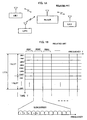
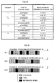
- FIG. 1A is a block diagram showing a radio mobile communications system in general
- FIG. 1B is a format diagram showing a signal frame structure in LTE.
- one slot is equivalent to 0.5 msec and is composed of seven long blocks (LBs), and two slots constitute one transmission time interval (TTI).
- TTI is as long a time interval as a plurality of blocks (a transport block set) transferred at a time between the physical layer and the MAC layer.
- the bandwidth (the number of subcarriers) of a single frequency resource block (RB) is 12 subcarriers, and control signals and/or reference signals of individual mobile stations (UEs) are placed in each frequency resource block.
- a resource block is composed of 7 LBs in time direction and 12 subcarriers in frequency direction.
- An uplink control signal needs to carry a data-non-associated control signal, which is feedback information about a downlink signal.
- the data-non-associated control signal includes at least "Acknowledgment/Negative Acknowledgment” (hereinafter, referred to as "ACK/NACK”), which indicates whether or not downlink information has been received without error, as well as channel quality indicator information (hereinafter, referred as "CQI”), which indicates the quality of the downlink channel, and the like.
- ACK/NACK Acknowledgment/Negative Acknowledgment
- CQI channel quality indicator information
- the transmission delay of ACK/NACK be short.
- the transmission frequency is determined with consideration given to the transmission overhead and the moving speed of the mobile station. Accordingly, there are some occasions when the frequency of transmission of ACK/NACK differs from that of CQI, in which case mobile stations transmitting three types of control signals coexist within a single TTI: those which transmit ACK/NACK only, those which transmit CQI only, and those which transmit both of ACK/NACK and CQI. In addition, since the amount of ACK/NACK information is smaller than that of CQI information, these three types of control signals differ from each other in amount of information and transmission bandwidth.
- FDM frequency division multiplexing
- CDM code division multiplexing
- CAZAC Constant Amplitude Zero Auto-Correlation sequence
- Zadoff-Chu sequence represented by the following equation 1 has been known (see B. M. Popovic, "Generalized Chirp-Like Polyphase Sequences with Optimum Correlation Properties," IEEE Transactions on Information Theory, Vol. 38, No.
- CAZAC sequences are sequences which have constant amplitude in both of the time and frequency domains and produce an autocorrelation value of zero at a phase difference of any value other than zero.
- the CAZAC sequences because of their property of perfect autocorrelation, signal separation is possible without interference from other users in the case of CDM.
- the CAZAC sequences are suitable for use in channel estimation in the frequency domain because of the constant amplitude also in the frequency domain. Accordingly, a CAZAC sequence is used as a reference signal (pilot signal) sequence.
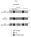
- FIG. 2 is a diagram showing an example of the allocation of resources to a control signal ACK/NACK and/or a control signal CQI in the frame format in LTE.
- one slot is equivalent to 0.5 msec and is composed of seven long blocks (LBs), and two slots constitute one transmission time interval (TTI).
- TTI transmission time interval
- UEs individual mobile stations
- CAZAC sequences are used as spreading codes
- only those mobile stations which transmit signals using the same transmission bandwidth can be orthogonally multiplexed.
- every mobile station performs single-carrier transmission, with no application of multi-code transmission or multi-carrier transmission, by which the PAPR is increased.
- FIG. 2 shown is an example where, within a TTI, resources are allocated to ACK/NACK only (except a reference signal) for a mobile station UE1, resources are allocated to CQI only (except a reference signal) for a mobile station UE2, and resources are allocated to ACK/NACK and CQI (except a reference signal) for a mobile station UE3.
- the reference signals are used to demodulate control signals.
- the control signals of the mobile station UE3, ACK/NACK & CQI are time-division-multiplexed at LB level.
- the respective control resources for ACK/NACK and CQI of the mobile station UE3 are reduced in comparison with those for ACK/NACK and CQI of the other mobile stations UE1 and UE2. Accordingly, at least the properties of ACK/NACK & CQI of the mobile station UE3 are more degraded than the property of ACK/NACK of the mobile station UE1 and the property of CQI of the mobile station UE2.
- WO2006/130742 A discloses to adjust the transmitting power for ACK based on a measured performance or an ACK channel, i.e. the quality of the channel is degraded the resource for ACK is increased to improve the quality of transmission.
- the transmission rate of an acknowledgement message is changed in response to the estimated transmission quality of the transmission channel.
- An object of the present invention is to provide a resource allocation control method and device that can achieve the efficient allocation of control resource between multiple types of control signals.
- a method of controlling resource allocation in a resource block of a fixed amount including control resources used for a plurality of types of control signals and reference resources used for reference signals, to radio communications between a plurality of radio stations includes: measuring propagation channel quality between a first radio station and a second radio station at one or both of the first and second radio stations; determining a resource ratio of the plurality of types of control signals in the control resources based on the propagation channel quality; and notifying the other one of the first and second radio stations of the resource ratio.
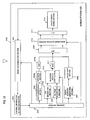
- FIG. 1A is a block diagram showing a radio mobile communications system in general.
- FIG. 1B is a format diagram showing a signal frame structure in LTE.
- FIG. 2 is a diagram showing an example of the allocation of resources to a control signal ACK/NACK and/or a control signal CQI in the frame format in LTE.
- FIG. 3 is a block diagram showing a schematic configuration of a base station in a mobile radio system according to a first exemplary embodiment of the present invention.
- FIG. 4 is a block diagram showing a schematic configuration of a mobile station (UE) in the mobile radio system according to the first exemplary embodiment of the present invention.
- FIG. 5 is a schematic diagram showing an example of CAZAC sequences with cyclic shifts added thereto.
- FIG. 6A is a flow chart of the operations of the base station executing resource allocation control according to the first exemplary embodiment of the present invention.
- FIG. 6B is a flow chart of the operations of the mobile station in the first exemplary embodiment of the present invention.
- FIG. 7A is a table schematically showing a first example of resource apportionment according to the first exemplary embodiment of the present invention.
- FIG. 7B is a diagram showing the allocation of resources to a control signal ACK/NACK and/or a control signal CQI, according to the resource apportionment shown in FIG. 7A .
- FIG. 8 is a table schematically showing a second example of resource apportionment according to the first exemplary embodiment of the present invention.
- FIG. 9 is a block diagram showing a schematic configuration of a base station in a mobile radio system according to a second exemplary embodiment of the present invention.
- FIG. 10 is a block diagram showing a schematic configuration of a mobile station in the mobile radio system according to the second exemplary embodiment of the present invention.
- FIG. 11A is a flow chart of the operations of the base station in the second exemplary embodiment of the present invention.
- FIG. 11B is a flow chart of the operations of the mobile station executing resource allocation control according to the second exemplary embodiment of the present invention.
- FIG. 12 is a diagram showing the allocation of resources to a reference signal and a control signal ACK/NACK and/or a control signal CQI according to the second exemplary embodiment of the present invention.
- FIG. 13 is a block diagram showing a schematic configuration of a mobile station in a mobile radio system according to a third exemplary embodiment of the present invention.
- FIG. 14A is a table schematically showing an example of resource apportionment according to the third exemplary embodiment of the present invention.
- FIG. 14B is a diagram showing an example of the allocation of resources to control signals ACK/NACK and CQI, according to the resource apportionment shown in FIG. 14A .
- the probability that a resource is allocated to data is small, resulting in the decreased degree of importance of CQI, therefore not leading to great degradation in throughput.
- efficiency in channel-dependent scheduling can be enhanced by increasing the number of transmission bits for CQI.
- the ratio between the control resource used for ACK/NACK and the control resource used for CQI is controlled depending on the channel quality.
- a format to be used can be restricted by changing the modulation scheme and encoding rate (MCS: Modulation and Coding Scheme) for each control signal, and by controlling the transmission power.
- MCS Modulation and Coding Scheme
- the format is a signal placement structure which is determined depending on the positions of control and reference signals.
- formats can be said to be the same if the positional relationship among each control signal and reference signal is the same.
- Formats are said to be different if, as UE1 to UE3 show in FIG. 2 , the positions (LB positions) at which control signals are respectively transmitted differ among mobile stations.
- a base station (also referred to as "NodeB”) takes initiative in controlling the ratio between control resources within a resource block, and in controlling the ratio between control and reference resources within a resource block.
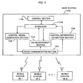
- FIG. 3 is a block diagram showing a schematic configuration of a base station in a mobile radio system according to the first exemplary embodiment of the present invention.
- the base station 100 accommodates N mobile stations (UEs) 1 to N.
- a radio communication section 101 demodulates an uplink control signal received from a mobile station, in accordance with a reference signal similarly received, and outputs the demodulated control signal and the reference signal to a control information extraction section 102 and a CQI measurement section 103 respectively.
- the control information extraction section 102 extracts resource allocation information, such as a request for resource allocation here, and outputs the extracted information to a scheduler 104.
- the CQI measurement section 103 performs CQI measurement using the reference signal obtained from the radio communication section 101, in response to a request to measure CQI for a mobile station designated by the scheduler 104, and outputs the measured CQI value back to the scheduler 104.
- the scheduler 104 under the control of a control section 106, performs resource allocation within a resource block for the mobile station based on the measured CQI value, and outputs information regarding this resource allocation (resource allocation information) to a control signal generation section 105.
- the control signal generation section 105 generates a control signal containing this resource allocation information for the mobile station and transmits the control signal to the mobile station through the radio communication section 101.
- the control section 106 controls the overall operations of the base station 100. Scheduling by the scheduler 104 is performed under the control of the control section 106. In general, the control section 106 performs various kinds of control, such as resource allocation control, by executing control programs on a program-controlled processor such as a central processing unit (CPU).
- a program-controlled processor such as a central processing unit (CPU).
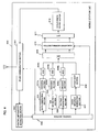
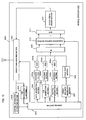
- FIG. 4 is a block diagram showing a schematic configuration of a mobile station (UE) in the mobile radio communications system according to the first exemplary embodiment of the present invention
- FIG. 5 is a schematic diagram showing an example of CAZAC sequences with cyclic shifts added thereto.
- a radio communication section 201 demodulates a downlink control signal and/or downlink data received from the base station 100, by using a reference signal similarly received, and outputs the demodulated control signal to a control information extraction section 202.
- the control information extraction section 202 extracts resource allocation information and information regarding a desired value of transmission power and outputs the extracted information to a control section 203.
- the control section 203 controls each of the radio communication section 201, a data generation section 204, a CQI generation section 205, an ACK/NACK generation section 206, a CAZAC sequence generation section 207, a cyclic shift section 208, and a subcarrier mapping section 210.
- Data and/or control signals generated by the data generation section 204, CQI generation section 205, and ACK/NACK generation section 206 are encoded by encoding sections 204a, 205a, and 206a respectively, then modulated by modulation sections 204b, 205b, and 206b respectively, and then output to a discrete Fourier transformation (DFT) section 209.
- DFT discrete Fourier transformation
- the CAZAC sequence generation section 207 generates a CAZAC sequence
- the cyclic shift section 208 adds to the CAZAC sequence as many cyclic shifts as are equivalent to a time length uniquely assigned to the mobile station and outputs a resultant cyclically shifted CAZAC sequence to the DFT section 209.
- the orthogonality between mobile stations can be accomplished by setting the amount of a cyclic shift equal to or larger than a maximum channel delay. For example, the amount of a cyclic shift is set equal to the length of a cyclic prefix.
- the cyclic shift section 208 may also be placed after an inverse Fourier transformation (IFFT) section 209 and before a cyclic prefix adding section 212.
- IFFT inverse Fourier transformation
- control section 203 controls the encoding sections 204a to 206a and/or modulation sections 204b to 206b in accordance with the control information.
- the DFT section 209 transforms the data and/or control signals into signals in the frequency domain
- the signals of individual frequency components are output to the subcarrier mapping section 210.
- the subcarrier mapping section 210 chooses which signals in the frequency domain will be transmitted (subcarrier mapping).
- the subcarrier mapping section 210 can perform subcarrier mapping by localized FDM (LFDM), in which contiguous subcarriers are used, or subcarrier mapping by distributed FDM (DFDM), in which subcarriers at fixed intervals are used.
- LFDM localized FDM
- DFDM distributed FDM
- the signals in the frequency domain thus subcarrier-mapped are transformed into signals in the time domain by the IFFT section 211, and then a cyclic prefix (CP) is added by the cyclic prefix adding section 212.
- the data, control signals, and reference signal thus output from the cyclic prefix adding section 212 are transmitted to the base station 100 through the radio communication section 201.
- the control section 203 performs transmission power control by controlling the radio communication section 201 in accordance with the information regarding the required value of transmission power obtained from the control information extraction section 202.
- resource allocation control according to the first exemplary embodiment of the present invention is performed as described below.
- FIG. 6A is a flow chart of the operations of the base station executing resource allocation control according to the first exemplary embodiment of the present invention
- FIG. 6B is a flow chart of the operations of the mobile station. Note that in FIGS. 6A and 6B , the transmission/reception relationship between the base station and the mobile station is indicated by broken arrows. In FIGS. 6A and 6B , uplink and downlink are denoted by UL and DL, respectively.
- the base station 100 allocates a resource to an uplink reference signal to measure the quality of an uplink channel (Step 400).
- the control signal generation section 105 generates a downlink control signal containing information regarding this resource allocation, which is then transmitted from the radio communication section 101 to the mobile station in question (Step 401).
- This control signal is transmitted through a physical downlink control channel (PDCCH) or the like.
- PDCCH physical downlink control channel
- the mobile station responds to this control signal as will be described later, and the radio communication section 101 of the base station 100 receives the uplink reference signal from the mobile station (Step 402). Then, the CQI measurement section 103 measures the uplink CQI (Step 403).
- the scheduler 104 determines whether or not to notify that the mobile station will transmit multiple types of uplink control signals (Step 404). In the case of notifying that the mobile station will transmit multiple types of uplink control signals (Step 404: YES), the scheduler 104 determines the ratio between the resources for the control signals, based on the CQI measured at Step 403 (Step 405). This determination of the resource ratio will be described later. Further, based on the CQI, the scheduler 104 determines the modulation scheme and encoding rate (MCS: Modulation and Coding Scheme) for each control signal (Step 406). Note that when the uplink control signal to be transmitted is of a single type (Step 404: NO), then Step 406 is performed, with Step 405 being skipped.
- MCS Modulation and Coding Scheme
- the scheduler 104 determines the transmission power and the ratio between the reference signal and the control signals in accordance with the CQI, which will be described later (Step 407).
- the control signal generation section 105 generates a downlink control signal containing information regarding the thus-determined resource allocation (resource allocation information), which is then transmitted from the radio communication section 101 to the mobile station (Step 408).
- the resource allocation information includes the ratio between the resources for the control signals, modulation scheme and coding rate (MCS) for each control signal, required value of transmission power, ratio between the resources for the reference signal and the control signals, and the like.
- MCS modulation scheme and coding rate
- the radio communication section 201 receives a downlink control signal transmitted by the base station 100 (the downlink control signal transmitted at Step 401 in FIG. 6A ) (Step 500).
- the control information extraction section 202 then extracts information regarding the allocation of a resource to an uplink reference signal from the downlink control signal (Step 501).
- the control section 203 controls the CAZAC sequence generation section 207 and the cyclic shift section 208, thereby transmitting the uplink reference signal for CQI measurement in accordance with the information extracted at Step 501 (Step 502).
- This uplink reference signal is received by the base station 100 (Step 402 in FIG. 6A ).
- the radio communication section 201 of the mobile station 200 receives a downlink control signal from the base station 100 (Step 503), and the control information extraction section 202 extracts information regarding the allocation of resources to uplink control signals (resource allocation information) (Step 504).
- This resource allocation information received from the base station 100 includes the above-described information determined at Step 404 through Step 407, namely, the ratio between the resources for the control signals, MCS for each control signal, required value of transmission power, ratio between the resources for the reference signal and the control signals, and the like.
- the control section 203 transmits the uplink control signals and the reference signal in accordance with the extracted resource allocation information (Step 505).
- the uplink control signals are transmitted through a physical uplink control channel (PUCCH) or the like.
- PUCCH physical uplink control channel
- FIG. 7A is a table schematically showing a first example of resource apportionment according to the first exemplary embodiment of the present invention
- FIG. 7B is a diagram showing the allocation of resources to a control signal ACK/NACK and/or a control signal CQI according to the resource apportionment shown in FIG. 7A
- FIG. 7A shows the relationship between the measured channel quality (CQI level) and the frame format (ratio among the resource used for ACK/NACK, the resource used for CQI, and the reference resource). It is assumed that CQI in FIG. 7A has four levels (levels 1 to 4), and that the channel quality becomes better as the CQI level rises from 1 to 4. Note, however, that although four CQI levels are shown here as an example, the number of CQI levels is not limited to this. It is also possible to perform the resource allocation control, with as many CQI levels as necessary being set.
- the ratio of the resource used for ACK/NACK is reduced while the ratio of the resource used for CQI is increased as the CQI level rises, as shown in FIG. 7A .
- the ratio of the resource used for ACK/NACK is 8 and the ratio of the resource used for CQI is 2 but for ACK/NACK & CQI at a CQI level of 4, the ratio of the resource used for ACK/NACK is 4 and the ratio of the resource used for CQI is 8.
- channel estimation needs to be done for the demodulation of control signals such as ACK/NACK and CQI, and precision in channel estimation is dependent on the signal-to-noise ratio (SNR) of a reference signal.
- SNR signal-to-noise ratio
- the ratio of the reference resource is made larger than when a channel is in good condition, thereby increasing the SNR of the reference signal.
- the base station 100 can perform similar resource allocation control only by notifying a mobile station of a notification number. This makes it possible to reduce the number of transmission bits for a downlink control signal.
- the control signals of the plurality of mobile stations are code-division-multiplexed, and ACK/NACK and CQI of each mobile station are time-division-multiplexed at LB level.
- the CQI level is 4, which means that the channel quality is good.
- the frame format in a resource block only is changed depending on the channel quality.
- the modulation scheme and encoding rate (MCS) and the desired value of transmission power also can be changed.
- MCS modulation scheme and encoding rate
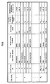
- FIG. 8 is a table schematically showing a second example of resource apportionment according to the first exemplary embodiment of the present invention.
- FIG. 8 shows the relationship among the measured channel quality (CQI level), frame format, MCS, and required value of transmission power.
- CQI channel quality
- MCS frame format
- required value of transmission power it is assumed that CQI has Q N levels, and that the channel quality becomes better as the CQI level rises from 1 to Q N .
- P required value of transmission power is controlled at M levels, where P 1 > P 2 > ... > P M .
- the ratio of the resource used for ACK/NACK is reduced while the ratio of the resource used for CQI is increased.
- the modulation scheme for CQI is changed from the quadrature phase shift keying (QPSK) providing two-bit transmission, to the 16 quadrature amplitude modulation (16QAM), which is one of QAM schemes providing four-bit transmission, whereby the encoding rate is increased, thus increasing the number of transmission bits for CQI.
- QPSK quadrature phase shift keying
- 16QAM 16 quadrature amplitude modulation
- the CQI level is high, the required value of transmission power is reduced, whereby interference power is reduced and the efficiency of power usage is increased.
- modulation scheme encoding rate
- required value of transmission power is changed in addition to the frame format in this second example, it is also possible that a change is made in any one, or multiple selected ones, of the modulation scheme, coding rate, and required value of transmission power.
- the base station takes initiative in performing the control for allocating optimum amounts of resources to a reference signal and multiple control signals having different required conditions, such as ACK/NACK and CQI, depending on the channel quality.
- the efficiency of resource usage can be enhanced.
- the allocation of resources to the uplink signals is performed depending on the uplink CQI, it can be expected that the effects are brought about particularly in frequency division duplex (FDD) systems.
- FDD frequency division duplex
- the base station that takes initiative in performing the control for apportioning the control and reference resources within a resource block.
- a mobile station takes initiative in performing similar control.
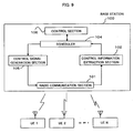
- FIG. 9 is a block diagram showing a schematic configuration of a base station in a mobile radio system according to a second exemplary embodiment of the present invention.
- the base station in the second exemplary embodiment has a configuration similar to that of the base station in the first exemplary embodiment described with reference to FIG. 3 , except that the base station in the second exemplary embodiment is not provided with the CQI measurement section 103. Therefore, in the second exemplary embodiment, those blocks having the same functions as in the first exemplary embodiment are denoted by the same reference numerals, and description thereof will be omitted.
- FIG. 10 is a block diagram showing a schematic configuration of a mobile station.
- This mobile station also has a configuration similar to that of the mobile station in the first exemplary embodiment described with reference to FIG. 4 , except that a CQI measurement section 300 is added to the mobile station in the second exemplary embodiment. Therefore, in the second exemplary embodiment, those blocks having the same functions as in the first exemplary embodiment are denoted by the same reference numerals, and description thereof will be omitted.
- the CQI measurement section 300 performs CQI measurement using a reference signal received by the radio communication section 201 and outputs the result of the measurement to the control section 203.
- resource allocation control according to the second exemplary embodiment is performed as described below.
- FIG. 11A is a flow chart of the operations of the base station
- FIG. 11B is a flow chart of the operations of the mobile station executing resource allocation control according to the second exemplary embodiment of the present invention. Note that in FIGS. 11A and 11B , the transmission/reception relationship between the base station and the mobile station is indicated by broken arrows. In FIGS. 11A and 11B , uplink and downlink are denoted by UL and DL, respectively.
- the scheduler 104 performs the allocation of the control resources on the whole for each mobile station to transmit uplink control information (Step 1000). Then, resource allocation information containing information about these control resources, and a reference signal for CQI measurement are transmitted to each mobile station from the radio communication section 101 (Step 1001). In response to this, the radio communication section 101 receives from each mobile station an uplink control signal containing information about the ratio between the resources for control signals, information about the MCS for each control signal, and the like (Step 1002). This uplink control signal is transmitted through PUCCH or the like.
- the control information extraction section 102 extracts the information about the ratio between the control resources, which is transmitted in a predetermined resource, from the uplink control signal received at Step 1002 (Step 1003), and demodulates information about ACK/NACK and/or CQI and the like by using this extracted information (Step 1004).
- the predetermined resource used to transmit the information about the resource ratio is a resource composed of a given number of long blocks (LBs). For example, two LBs like the first two LBs shown in FIG. 12 are the predetermined resource.
- the radio communication section 201 receives a reference signal and a downlink control signal containing information about the allocation of the control resources on the whole from the base station 100 (Step 1100).
- the CQI measurement section 300 measures CQI by using the received reference signal (Step 1101).
- the control section 203 determines whether or not it is necessary to transmit multiple types of uplink control signals (Step 1102).
- the control section 203 determines the ratio between the resources to be allocated to the multiple control signals, by using the CQI measured by the CQI measurement section 300 (Step 1103), and further determines the MCS for each control signal, based on the measured CQI (Step 1104).
- the ratio between the resources to be allocated, MCS, and the like may be determined as in the first exemplary embodiment, in a similar manner as shown in FIG. 7 or 8 .
- the uplink control signal is of a single type (not multiple types) (Step 1102: NO)
- Step 1103 being skipped.
- an uplink control signal is generated which contains, as uplink control information, information about the resource ratio and the MCS for each control signal determined at Step 1103 and Step 1104 respectively (Step 1105). Moreover, after the uplink transmission power is determined based on the CQI (Step 1106), the generated uplink control signal is transmitted to the base station 100 (Step 1107).
- the base station 100 can demodulate the allocation information because the position at which the allocation information about the resource ratio is located is already known. Using the demodulated allocation information, ACK/NACK and/or CQI are demodulated (Step 1004 in FIG. 11A ).
- FIG. 12 is a diagram showing the allocation of resources to a reference signal and control signals ACK/NACK and CQI according to the second exemplary embodiment, showing an example of frame formats to transmit the uplink control signal generated at Step 1105 in FIG. 11B .
- the allocation information about the resource ratio is transmitted by using a predetermined resource within a resource block.
- the first two LBs are provided as the predetermined resource to transmit the allocation information, independently of the ratio between the resources for ACK/NACK and CQI. It is possible for the base station 100 to demodulate the allocation information because, as mentioned above, the position of the resource for the allocation information about the resource ratio is already known.
- resource allocation within a resource block is performed based on the CQI measured using a downlink reference signal.
- resource allocation can also be performed based on the MCS for downlink data, the number of ACKs/NACKs (number of retransmissions) responding to uplink data, or the like. 3.3) Advantages
- the mobile station takes initiative in performing the control for allocating optimum amounts of resources to a reference signal and multiple control signals having different required conditions, such as ACK/NACK and CQI, depending on the channel quality.
- the efficiency of resource usage can be enhanced.
- the allocation of resources to uplink signals is performed in accordance with channel information such as the downlink CQI. Accordingly, it can be hoped that the effects are brought about particularly in time division duplex (TDD) systems, in which the same transmission frequencies are used for downlink and uplink.
- TDD time division duplex
- the present invention is not limited to this scheme. It is also possible to employ Joint Coding by which multiple types of control signals are encoded by a single encoding section. According to this scheme, multiple types of control signals are multiplexed at bit level in each long block.
- FIG. 13 is a block diagram showing a schematic configuration of a mobile station in a mobile radio system according to a third exemplary embodiment of the present invention.
- the mobile station in the third exemplary embodiment has a configuration similar to that of the mobile station in the first exemplary embodiment, except that a single encoding section 310 is used in place of the encoding sections 205a and 206a in FIG. 4 , and that a single modulation section 311 modulates an output from the encoding section 310. Therefore, in the third exemplary embodiment, those blocks having the same functions as in the first exemplary embodiment are denoted by the same reference numerals, and description thereof will be omitted.
- the encoding section 310 receives control signals CQI and ACK/NACK composed different numbers of bits from the CQI generation section 205 and the ACK/NACK generation section 206 respectively as input.
- the encoding section 310 controls the encoding rate for each of the control signals, thereby producing the same number of output bits for each of the control signals, which are then output to the modulation section 311. Accordingly, while the reference and control signals are multiplexed at LB level, the multiple types of control signals are multiplexed at bit level.
- the ratio between the numbers of bits of these control signals multiplexed, encoding rate is controlled depending on the channel quality, as described below.
- the same concept that is applied to the already-described "ratio between the resources to be allocated" can also be applied to the ratio between the numbers of bits in a single LB.
- FIG. 14A is a table schematically showing an example of resource apportionment according to the third exemplary embodiment of the present invention
- FIG. 14B is a diagram showing an example of the allocation of resources to the control signals ACK/NACK and CQI according to the resource apportionment shown in FIG. 14A
- FIG. 14A shows the relationship between the measured channel quality (CQI level) and the resources used for ACK/NACK and used for CQI. It is assumed that CQI in FIG. 14A has four levels (levels 1 to 4), and that the channel quality becomes better as the CQI level rises from 1 to 4. Note, however, that although four CQI levels are shown here as an example, the number of CQI levels is not limited to this. It is also possible to perform the resource allocation control, with as many CQI levels as necessary being set.
- the ratio of the resource (the number of bits) used for CQI is increased as the CQI level rises, thereby increasing the coding rate.
- the ratio of the resource (the number of bits) used for ACK/NACK is 1 whereas the ratio of the resource (the number of bits) used for CQI is 4.
- the ratio of the resource used for ACK/NACK is 1 whereas the ratio of the resource used for CQI is 8.
- the present invention is not limited to this. The present invention can also be similarly applied to the case where ACK/NACK is composed of a plurality of bits.
- resource allocation control can be performed as in the first exemplary embodiment described earlier. Additionally, if a table as shown in FIG. 14A is provided to each of the base station 100 and the mobile station 200 and a notification number is assigned beforehand to each control item (resource ratio associated with a CQI level and with a control signal type), then the base station 100 can perform similar resource allocation control only by notifying a mobile station of a notification number. This makes it possible to reduce the number of transmission bits for a downlink control signal.
- control signals can be multiplexed at bit level in each long block as shown in FIG. 14B , and the coding rates for these control signals can be changed depending on the channel quality. Accordingly, depending on the channel quality, optimum amounts of resources can be allocated respectively to a reference signal and multiple control signals having different required conditions, such as ACK/NACK and CQI, whereby the efficiency of resource usage can be enhanced. Moreover, in conjunction with this scheme, it is also possible to adopt the changing of the modulation scheme and the transmission power as described in the first and second exemplary embodiments.
- the first object of the present invention is to provide a resource allocation control method and device that can achieve the efficient allocation of control resources between multiple types of control signals.
- Another object of the present invention is to provide a method and an apparatus for resource allocation control that can accomplish the efficient apportionment of resources among a reference signal and multiple types of control signals.
- a method of controlling resource allocation in a resource block including control resources used for a plurality of types of control signals and reference resources used for reference signals, to radio communications between a plurality of radio stations includes: measuring propagation channel quality between a first radio station and a second radio station at one or both of the first and second radio stations; determining resource apportionment of the plurality of types of control signals in the control resources based on the propagation channel quality; and notifying the other one of the first and second radio stations of the resource apportionment.
- optimum amounts of resources can be allocated respectively to multiples types of control signals having different required conditions, or respectively to a reference signal and control signals, whereby the efficiency of resource usage can be enhanced. Even when not all the required conditions of the control signals are satisfied in particular, the efficient use of resources can be accomplished by controlling the resource ratio while considering the degree of importance of each control signal.
- the first radio station and the second radio station may be a base station and a mobile station of a mobile radio communications system, respectively.
- the first radio station may measure the propagation channel quality using the reference signal received from the second station and notify the second station of the resource apportionment which is determined based on the propagation channel quality.
- the second radio station may measure the propagation channel quality using the reference signal received from the first station and notify the first station of the resource apportionment which is determined based on the propagation channel quality.
- the resource apportionment of control and reference resources within the resource block may be determined based on the propagation channel quality.
- the ratio of the control resources within the resource block is increased and the ratio of the reference resources is decreased as the propagation channel quality becomes better.
- the plurality of types of control signals may include channel quality information which indicates the propagation channel quality, wherein the ratio of resource allocated to the channel quality information within the control resources is increased as the propagation channel quality becomes better.
- At least one of modulation scheme, encoding rate and transmission power may be set for at least one of the plurality of types of control signals based on the propagation channel quality.
- at least one of controls of: increasing number of modulation levels; increasing an encoding rate; and decreasing transmission power, may be performed as the propagation channel quality becomes better.
- the present invention can be applied to mobile radio systems in general in which resource allocation is performed.
Landscapes
- Engineering & Computer Science (AREA)
- Signal Processing (AREA)
- Computer Networks & Wireless Communication (AREA)
- Quality & Reliability (AREA)
- Mobile Radio Communication Systems (AREA)
- Digital Transmission Methods That Use Modulated Carrier Waves (AREA)
Claims (19)
- Procédé de commande d'allocation de ressources dans un bloc de ressources d'une quantité fixe comprenant des ressources de commande utilisées pour des signaux de commande d'admission/non-admission et d'indicateur de qualité de canal et des ressources de référence utilisées pour des signaux de référence, pour des communications radio entre une pluralité de stations radios, comprenant :la mesure (403, 1101) de la qualité du canal de propagation entre une première station radio et une seconde station radio au niveau d'une ou des deux des première et seconde stations radio ;la détermination (405, 1103) et la commande d'un rapport de ressources des signaux de commande d'admission/non-admission et d'indicateur de qualité de canal dans les ressources de commande d'après la qualité du canal de propagation et un degré d'importance de chacun des types des signaux de commande ; etla notification (408, 1107) du rapport de ressources à l'autre des première et seconde stations radios.
- Procédé selon la revendication 1, dans lequel la première station radio et la seconde station radio sont une station de base et une station mobile d'un système de communications radios mobile, respectivement.
- Procédé selon la revendication 2, dans lequel la première station radio mesure la qualité du canal de propagation à l'aide du signal de référence reçu de la seconde station et notifie à la seconde station le rapport de ressources qui est déterminée d'après la qualité du canal de propagation.
- Procédé selon la revendication 2, dans lequel la seconde station radio mesure la qualité du canal de propagation à l'aide du signal de référence reçu de la première station et notifie à la première station le rapport de ressources qui est déterminée d'après la qualité du canal de propagation.
- Procédé selon l'une quelconque des revendications 1 à 4, dans lequel le rapport de ressources des ressources de commande et de référence au sein du bloc de ressources est déterminé d'après la qualité du canal de propagation.
- Procédé selon la revendication 5, dans lequel le rapport des ressources de commande au sein du bloc de ressources augmente et le rapport des ressources de référence diminue tandis que la qualité du canal de propagation s'améliore.
- Procédé selon l'une quelconque des revendications 1 à 4, dans lequel les signaux de commande incluent une indication de qualité de canal qui indique la qualité de canal de propagation, dans lequel le rapport de ressources allouées à l'indication de qualité de canal dans les ressources de commande augmente tandis que la qualité du canal de propagation s'améliore.
- Procédé selon l'une quelconque des revendications 1 à 4, dans lequel au moins l'un d'un schéma de modulation, taux de codage et puissance d'émission est établi pour au moins un de la pluralité de types de signaux de commande d'après la qualité du canal de propagation.
- Procédé selon la revendication 8, dans lequel au moins l'une des commandes : d'augmentation du nombre de niveaux de modulation ; d'augmentation d'un taux de codage ; et de diminution de puissance d'émission est réalisée tandis que la qualité du canal de propagation s'améliore.
- Dispositif de commande d'allocation de ressources dans un bloc de ressources d'une quantité fixe comprenant des ressources de commande utilisées pour des signaux de commande d'admission/non-admission et d'indicateur de qualité de canal et des ressources de référence utilisées pour des signaux de référence, pour des communications radios entre une pluralité de stations radios, comprenant :une section de mesure (103, 300) pour mesurer la qualité du canal de propagation entre une première station radio et une seconde station radio au niveau d'une ou des deux des première et seconde stations radio ;une section d'établissement de rapport de ressource (104, 203) pour déterminer et commander un rapport de ressources des signaux de commande d'admission/non-admission et d'indicateur de qualité de canal dans les ressources de commande d'après la qualité du canal de propagation et un degré d'importance de chacun des types des signaux de commande ; etune section de communication (101, 201) pour notifier le rapport de ressources à l'autre des première et seconde stations radios.
- Dispositif selon la revendication 10, dans lequel la section d'établissement de rapport de ressources détermine le rapport de ressources des ressources de commande et de référence au sein du bloc de ressources d'après la qualité du canal de propagation.
- Dispositif selon la revendication 11, dans lequel, tandis que la qualité du canal de propagation s'améliore, la section d'établissement de rapport de ressources augmente le rapport des ressources de commande au sein du bloc des ressources et diminue le rapport des ressources de référence.
- Dispositif selon l'une quelconque des revendications 10 à 12, dans lequel les signaux de commande incluent une information de qualité de canal qui indique la qualité du canal de propagation, dans lequel la section d'établissement de rapport de ressources augmente le rapport de ressources alloué à l'indication de qualité de canal dans les ressources de commande tandis que la qualité du canal de propagation s'améliore.
- Dispositif selon l'une quelconque des revendications 10 à 12, dans lequel la section d' établissement de ressources établit au moins l'un d'un schéma de modulation, taux de codage et puissance d'émission pour au moins un des signaux de commande d'après la qualité du canal de propagation.
- Dispositif selon la revendication 14, dans lequel la section d'établissement de rapport de ressources réalise au moins une des commandes : d'augmentation du nombre des niveaux de modulation ; d'augmentation d'un taux de codage ; et de diminution de la puissance d'émission, tandis que la qualité du canal de propagation s'améliore.
- Dispositif selon l'une quelconque des revendications 10 à 12, dans lequel la première station radio et la seconde station radio sont une station de base et une station mobile d'un système de communications radio mobiles, respectivement, dans lequel la section de communication de la première station radio notifie le rapport de ressources à la seconde station.
- Dispositif selon l'une quelconque des revendications 10 à 12, dans lequel la première station radio et la seconde station radio sont une station mobile et une station de base d'un système de communications radios mobile, respectivement, dans lequel la section de communication de la première station radio notifie le rapport de ressources à la seconde station.
- Système de communications mobile comprenant une station de dispositif selon l'une quelconque des revendications 10 à 17.
- Programme donnant la consigne à un ordinateur de commander une allocation de ressources dans un bloc de ressources d'une quantité fixe comprenant des ressources de commande utilisées pour des signaux de commande d'admission/non-admission et d'indicateur de qualité de canal et des ressources de référence utilisées pour des signaux de référence, pour des communications radios entre une pluralité de stations radios, comprenant :la mesure de la qualité du canal de propagation entre une première station radio et une seconde station radio au niveau d'une ou des deux des première et seconde stations radios ;la détermination et la commande d'un rapport de ressources des signaux de commande d'admission/non-admission et d'indicateur de qualité de canal dans les ressources de commande d'après la qualité du canal de propagation et un degré d'importance de chacun des types de signaux de commande ; etla notification du rapport de ressources à l'autre des première et seconde stations radios.
Applications Claiming Priority (1)
| Application Number | Priority Date | Filing Date | Title |
|---|---|---|---|
| JP2007068879A JP5206921B2 (ja) | 2007-03-16 | 2007-03-16 | 移動無線システムにおけるリソース割当制御方法および装置 |
Publications (2)
| Publication Number | Publication Date |
|---|---|
| EP1973279A1 EP1973279A1 (fr) | 2008-09-24 |
| EP1973279B1 true EP1973279B1 (fr) | 2012-06-06 |
Family
ID=39672850
Family Applications (1)
| Application Number | Title | Priority Date | Filing Date |
|---|---|---|---|
| EP20080004699 Ceased EP1973279B1 (fr) | 2007-03-16 | 2008-03-13 | Procédé de contrôle d'affectation de ressources et dispositif dans un système de communications radio mobiles |
Country Status (5)
| Country | Link |
|---|---|
| US (1) | US8428011B2 (fr) |
| EP (1) | EP1973279B1 (fr) |
| JP (1) | JP5206921B2 (fr) |
| KR (1) | KR20080084702A (fr) |
| CN (1) | CN101267252A (fr) |
Families Citing this family (65)
| Publication number | Priority date | Publication date | Assignee | Title |
|---|---|---|---|---|
| BRPI0719541B1 (pt) | 2006-10-02 | 2020-02-11 | Lg Electronics, Inc. | Método de transmissão de sinal de controle de downlink |
| USRE44564E1 (en) | 2006-10-02 | 2013-10-29 | Lg Electronics Inc. | Method for transmitting control signal using efficient multiplexing |
| KR101049138B1 (ko) | 2007-03-19 | 2011-07-15 | 엘지전자 주식회사 | 이동 통신 시스템에서, 수신확인신호 수신 방법 |
| ES2902275T3 (es) | 2007-03-19 | 2022-03-25 | Lg Electronics Inc | Un método de asignación de recursos y un método para transmitir/recibir información de asignación de recursos en un sistema de comunicación móvil |
| JP4531784B2 (ja) * | 2007-03-20 | 2010-08-25 | 株式会社エヌ・ティ・ティ・ドコモ | ユーザ装置および送信方法 |
| JP4601637B2 (ja) | 2007-03-20 | 2010-12-22 | 株式会社エヌ・ティ・ティ・ドコモ | 移動局、送信方法及び無線通信システム |
| HUE030601T2 (en) * | 2007-04-11 | 2017-05-29 | ERICSSON TELEFON AB L M (publ) | Process and equipment in telecommunication system |
| KR100913090B1 (ko) | 2007-06-13 | 2009-08-21 | 엘지전자 주식회사 | 통신 시스템에서 확산 신호를 송신하는 방법 |
| KR100908063B1 (ko) | 2007-06-13 | 2009-07-15 | 엘지전자 주식회사 | 이동 통신 시스템에서 확산신호를 송신하는 방법 |
| EP2159930A1 (fr) * | 2007-06-15 | 2010-03-03 | Panasonic Corporation | Dispositif de communication radio, système de communication radio et procédé de communication radio |
| KR100900289B1 (ko) | 2007-06-21 | 2009-05-29 | 엘지전자 주식회사 | 직교 주파수 분할 다중화 시스템에서 제어 채널을 송수신하는 방법 |
| ES2645098T3 (es) * | 2007-07-06 | 2017-12-04 | Huawei Technologies Co., Ltd. | Sistema, método y aparato de comunicación móvil |
| EP2180621A4 (fr) * | 2007-08-14 | 2014-11-05 | Ntt Docomo Inc | Procédé de contrôle de communication, station mobile et station de base |
| JP4558020B2 (ja) * | 2007-08-14 | 2010-10-06 | 株式会社エヌ・ティ・ティ・ドコモ | ユーザ装置、送信方法及び通信システム |
| US9065646B2 (en) * | 2008-02-04 | 2015-06-23 | Nokia Solutions And Networks Oy | ACK/NACK channelization for resource blocks containing both ACK/NACK and CQI |
| US9030948B2 (en) * | 2008-03-30 | 2015-05-12 | Qualcomm Incorporated | Encoding and decoding of control information for wireless communication |
| US8675573B2 (en) * | 2008-05-05 | 2014-03-18 | Qualcomm Incorporated | Uplink resource management in a wireless communication system |
| JP5077080B2 (ja) * | 2008-06-02 | 2012-11-21 | 富士通セミコンダクター株式会社 | 通信装置及び通信方法 |
| JP2010016674A (ja) * | 2008-07-04 | 2010-01-21 | Fujitsu Ltd | 無線通信装置、無線通信システム、及び無線通信方法 |
| US8718021B2 (en) | 2008-07-07 | 2014-05-06 | Apple Inc. | Uplink control signal design for wireless system |
| US8509161B2 (en) | 2008-08-11 | 2013-08-13 | Sharp Kabushiki Kaisha | Systems and methods for OFDMA and SC-FDMA switching |
| US8472309B2 (en) * | 2008-08-20 | 2013-06-25 | Qualcomm Incorporated | Using CDMA to send uplink signals in WLANs |
| CN102177762A (zh) | 2008-10-15 | 2011-09-07 | 富士通株式会社 | 发送装置、接收装置、发送方法以及接收方法 |
| US8204020B2 (en) * | 2008-10-22 | 2012-06-19 | Lg Electronics Inc. | Method and apparatus for mapping resource unit in wireless communication system |
| US8432860B2 (en) * | 2008-10-22 | 2013-04-30 | Lg Electronics Inc. | Method and apparatus for mapping resource unit in wireless communication system |
| KR20100044696A (ko) * | 2008-10-22 | 2010-04-30 | 엘지전자 주식회사 | 무선통신 시스템에서 자원유닛 맵핑방법 |
| US8204021B2 (en) * | 2008-10-22 | 2012-06-19 | Lg Electronics Inc. | Method and apparatus of subchannelization in wireless communication system |
| WO2010050757A2 (fr) * | 2008-10-30 | 2010-05-06 | Lg Electronics Inc. | Procédé de transmission de signaux de référence en liaison descendante dans un système de communication sans fil à antennes multiples |
| KR101648775B1 (ko) * | 2008-10-30 | 2016-08-17 | 엘지전자 주식회사 | 무선 통신 시스템에서 harq 확인 응답 전송 및 전송 블록 재전송 방법 |
| KR101608777B1 (ko) | 2008-10-30 | 2016-04-04 | 엘지전자 주식회사 | 다중안테나를 갖는 무선 통신 시스템에서 레퍼런스 신호를 하향 전송하는 방법 |
| US8199708B2 (en) * | 2008-12-30 | 2012-06-12 | Telefonaktiebolaget L M Ericsson (Publ) | Allocation of uplink reference signals in a mobile communication system |
| CN101448332B (zh) * | 2008-12-31 | 2011-12-28 | 中兴通讯股份有限公司 | 大带宽系统中上行控制信道资源映射方法及装置 |
| CN101772164B (zh) * | 2009-01-04 | 2012-11-21 | 上海贝尔阿尔卡特股份有限公司 | 在基站中用于分配发送探测信号的时频资源的方法及装置 |
| MY158329A (en) * | 2009-02-05 | 2016-09-30 | Lg Electronics Inc | Method and apparatus of transmitting uplink control signal in wireless communication system |
| WO2010090467A2 (fr) | 2009-02-05 | 2010-08-12 | Lg Electronics Inc. | Procédé et appareil de transmission de signal de commande de liaison montante dans un système de communication sans fil |
| WO2010110566A2 (fr) * | 2009-03-22 | 2010-09-30 | 엘지전자 주식회사 | Procédé de transmission de signaux de référence de sondage dans un système de communication sans fil et appareil destiné à ce procédé |
| JP5557270B2 (ja) * | 2009-03-26 | 2014-07-23 | 京セラ株式会社 | 無線基地局、無線基地局におけるサウンディング制御方法、および無線基地局におけるサウンディング制御プログラム |
| KR101746537B1 (ko) * | 2009-04-21 | 2017-06-13 | 엘지전자 주식회사 | 무선 통신 시스템에서 제어 신호 송신 방법 및 이를 위한 장치 |
| US8340043B2 (en) | 2009-04-24 | 2012-12-25 | Sharp Kabushiki Kaisha | Wireless communication system, communication device, and communication method |
| KR101717521B1 (ko) * | 2009-04-26 | 2017-03-17 | 엘지전자 주식회사 | 무선 통신 시스템에서 상향링크 제어 신호 송신 방법 및 이를 위한 장치 |
| US20100278058A1 (en) * | 2009-05-04 | 2010-11-04 | Qualcomm Incorporated | Method and apparatus for facilitating multicarrier differential channel quality indicator (cqi) feedback |
| KR101759933B1 (ko) * | 2009-05-07 | 2017-07-20 | 엘지전자 주식회사 | Ack/nack을 전송하는 방법 및 장치 |
| US20120170683A1 (en) * | 2009-06-23 | 2012-07-05 | Frank Frederiksen | Methods, Apparatuses, and Related Computer Program Product for Information Channel Configuration |
| CN102484878B (zh) * | 2009-07-03 | 2015-06-17 | 苹果公司 | 用于无线系统的上行链路控制信号设计 |
| KR101770208B1 (ko) * | 2009-07-10 | 2017-08-22 | 엘지전자 주식회사 | 무선 통신 시스템에서 상향링크 제어 신호 송신 방법 및 이를 위한 장치 |
| JPWO2011004613A1 (ja) * | 2009-07-10 | 2012-12-20 | パナソニック株式会社 | 端末装置、基地局装置、フィードバック方法及び再送制御方法 |
| KR101650749B1 (ko) * | 2009-08-18 | 2016-08-24 | 삼성전자주식회사 | 릴레이를 위한 백홀 서브프레임의 제어 채널 자원 할당 방법 및 장치 |
| US8780826B2 (en) * | 2010-01-12 | 2014-07-15 | Qualcomm Incorporated | Continuous CDM/FDM structure for LTE uplink data |
| CN102238624A (zh) * | 2010-04-30 | 2011-11-09 | 北京三星通信技术研究有限公司 | 一种获取上行数据接收状况的方法 |
| JP5606836B2 (ja) * | 2010-08-31 | 2014-10-15 | 株式会社Nttドコモ | 無線通信システム及び移動端末装置 |
| WO2012169817A2 (fr) * | 2011-06-10 | 2012-12-13 | Lg Electronics Inc. | Procédé et appareil permettant d'émettre des informations d'état de canal dans un système à nœuds multiples |
| KR101878211B1 (ko) | 2011-09-19 | 2018-07-16 | 삼성전자주식회사 | 무선 통신 시스템에서 다중 빔포밍 송수신기를 운용하기 위한 장치 및 방법 |
| US10616827B2 (en) | 2012-07-10 | 2020-04-07 | Huawei Technologies Co., Ltd. | System and method for dynamically configurable air interfaces |
| US10122506B2 (en) * | 2014-12-23 | 2018-11-06 | Qualcomm Incorporated | Single TTI transmission of control data in wireless communications |
| JP6786485B2 (ja) * | 2015-06-24 | 2020-11-18 | 株式会社Nttドコモ | ユーザ装置、基地局及び通信方法 |
| US11095404B2 (en) * | 2015-07-31 | 2021-08-17 | Qualcomm Incorporated | Multiplexing downlink control information of same aggregation level by coding together |
| US11005631B2 (en) | 2015-09-24 | 2021-05-11 | Ntt Docomo, Inc. | Terminal, base station and radio communication method for separately encoding uplink control information |
| ES2832589T3 (es) | 2015-12-31 | 2021-06-10 | Nec Corp | Métodos y aparatos para transmitir y recibir información de enlace ascendente |
| EP3427423A1 (fr) * | 2016-03-11 | 2019-01-16 | Nokia Technologies Oy | Gestion de signalisation de rétroaction |
| CN107231690B (zh) * | 2016-03-25 | 2023-07-04 | 中兴通讯股份有限公司 | 信息发送方法及装置 |
| EP4283896A3 (fr) | 2016-05-13 | 2024-01-10 | Sony Group Corporation | Dispositif de communications et équipement d'infrastructure |
| EP3535919A4 (fr) | 2016-11-04 | 2020-06-24 | Telefonaktiebolaget LM Ericsson (publ) | Stratégies de transmission d'ack/nack |
| CN109891793B (zh) * | 2016-11-04 | 2022-04-12 | 瑞典爱立信有限公司 | 无线电节点和操作节点的方法 |
| JP2018117274A (ja) * | 2017-01-19 | 2018-07-26 | 富士通株式会社 | 無線基地局、無線通信システム、無線通信方法、及び無線端末 |
| JP7243059B2 (ja) * | 2018-07-18 | 2023-03-22 | 日本電気株式会社 | 基地局、無線端末、無線通信システム並びに無線通信制御方法及びプログラム |
Family Cites Families (39)
| Publication number | Priority date | Publication date | Assignee | Title |
|---|---|---|---|---|
| JP3491549B2 (ja) * | 1999-01-28 | 2004-01-26 | 松下電器産業株式会社 | ディジタル無線通信システム |
| SG87029A1 (en) * | 1999-05-08 | 2002-03-19 | Kent Ridge Digital Labs | Dynamically delayed acknowledgement transmission system |
| EP1214810A1 (fr) | 1999-09-20 | 2002-06-19 | Nokia Corporation | Procede et dispositif de protection contre les erreurs |
| US6466803B1 (en) * | 1999-10-19 | 2002-10-15 | Qualcomm, Incorporated | Multi-mode communications system with efficient oscillator synchronization |
| JP4409743B2 (ja) * | 2000-02-25 | 2010-02-03 | パナソニック株式会社 | 無線通信装置及び無線通信方式 |
| US7145887B1 (en) * | 2001-02-23 | 2006-12-05 | 3Com Corporation | Communication of packet arrival times to cable modem termination system and uses thereof |
| KR100547893B1 (ko) * | 2001-10-30 | 2006-02-01 | 삼성전자주식회사 | 이동통신시스템에서 역방향 채널의 전력 제어 방법 및 장치 |
| US20050141446A1 (en) | 2002-05-31 | 2005-06-30 | Mitsubishi Denki Kabushiki Kaisha | Communication system |
| US8165619B2 (en) * | 2002-10-02 | 2012-04-24 | Qualcomm Incorporated | Power allocation for power control bits in a cellular network |
| KR100988536B1 (ko) * | 2002-11-01 | 2010-10-20 | 인터디지탈 테크날러지 코포레이션 | 무선 통신 시스템용 채널 품질 예측 방법 |
| CN100492946C (zh) | 2003-06-27 | 2009-05-27 | 上海贝尔阿尔卡特股份有限公司 | 一种自适应正交频分复用(ofdm)系统中的反馈信息传输方法 |
| CN100531433C (zh) * | 2003-08-08 | 2009-08-19 | 三菱电机株式会社 | 通信终端和通信系统 |
| FI20031383A0 (fi) * | 2003-09-25 | 2003-09-25 | Nokia Corp | Menetelmä ja pakettiradiojärjestelmä kontrolloida siirtoyhteyden sovitusta |
| KR20050032796A (ko) | 2003-10-02 | 2005-04-08 | 삼성전자주식회사 | 셀룰라 무선 패킷망에서 부하량 제어를 통한 망용량 증대방법 |
| KR100560386B1 (ko) * | 2003-12-17 | 2006-03-13 | 한국전자통신연구원 | 무선 통신 시스템의 상향 링크에서 코히어런트 검출을위한 직교주파수 분할 다중 접속 방식의 송수신 장치 및그 방법 |
| US7570968B2 (en) * | 2003-12-29 | 2009-08-04 | Samsung Electronics Co., Ltd | Method and apparatus for adaptive open-loop power control in mobile communication system using TDD |
| KR100606062B1 (ko) | 2004-02-26 | 2006-07-26 | 삼성전자주식회사 | 이동통신 시스템에서 시변채널의 특성에 따라 채널품질정보의 전송을 제어하는 방법 |
| JP2005269003A (ja) * | 2004-03-17 | 2005-09-29 | Victor Co Of Japan Ltd | ディジタル変調信号の送受信方法 |
| JP2005277570A (ja) * | 2004-03-23 | 2005-10-06 | Fujitsu Ltd | 送信装置、受信装置、再送制御方法 |
| JP4453491B2 (ja) * | 2004-08-16 | 2010-04-21 | 富士通株式会社 | 移動局 |
| JP2006067433A (ja) * | 2004-08-30 | 2006-03-09 | Fujitsu Ltd | 移動通信システム、無線基地局 |
| JP4412181B2 (ja) * | 2005-01-21 | 2010-02-10 | 株式会社日立製作所 | 適応変調方法並びに符号化率制御方法 |
| US7546136B2 (en) * | 2005-04-29 | 2009-06-09 | Telefonaktiebolaget L M Ericsson (Publ) | Variable transmit power control strategies for high-speed downlink packet access systems |
| US8879511B2 (en) * | 2005-10-27 | 2014-11-04 | Qualcomm Incorporated | Assignment acknowledgement for a wireless communication system |
| SG162735A1 (en) | 2005-05-31 | 2010-07-29 | Qualcomm Inc | Assignment acknowledgement for a wireless communication system |
| JP4834352B2 (ja) | 2005-06-14 | 2011-12-14 | 株式会社エヌ・ティ・ティ・ドコモ | 基地局、移動局及び電力制御方法 |
| US20060281462A1 (en) * | 2005-06-14 | 2006-12-14 | Samsung Electronics Co., Ltd. | Method for performing handover in a mobile communication system |
| CA2626895C (fr) * | 2005-11-11 | 2013-11-05 | Lg Electronics Inc. | Procede de controle de communications relais |
| US20070171849A1 (en) * | 2006-01-03 | 2007-07-26 | Interdigital Technology Corporation | Scheduling channel quality indicator and acknowledgement/negative acknowledgement feedback |
| US7929962B2 (en) * | 2006-05-01 | 2011-04-19 | Alcatel-Lucent Usa Inc. | Method for controlling radio communications during idle periods in a wireless system |
| JP2007329588A (ja) * | 2006-06-06 | 2007-12-20 | Fujitsu Ltd | 送信機及び送信方法 |
| US8374161B2 (en) * | 2006-07-07 | 2013-02-12 | Qualcomm Incorporated | Method and apparatus for sending data and control information in a wireless communication system |
| US9143288B2 (en) * | 2006-07-24 | 2015-09-22 | Qualcomm Incorporated | Variable control channel for a wireless communication system |
| US8571120B2 (en) * | 2006-09-22 | 2013-10-29 | Texas Instruments Incorporated | Transmission of acknowledge/not acknowledge (ACK/NACK) bits and their embedding in the reference signal |
| KR101090911B1 (ko) * | 2006-09-26 | 2011-12-08 | 노키아 코포레이션 | 업링크 제어 시그날링을 위한 시퀀스 변조를 제공하는 장치, 방법 및 컴퓨터 프로그램 제품 |
| KR101050955B1 (ko) * | 2006-10-04 | 2011-07-20 | 콸콤 인코포레이티드 | 무선 통신 시스템에서 sdma를 위한 업링크 ack 전송 |
| US8005107B2 (en) * | 2007-02-06 | 2011-08-23 | Research In Motion Limited | Method and system for robust MAC signaling |
| US8498639B2 (en) * | 2007-02-09 | 2013-07-30 | Qualcomm Incorporated | Flexible channel quality indicator reporting |
| EP2140601A1 (fr) * | 2007-03-14 | 2010-01-06 | Interdigital Technology Corporation | Transmission d'accusé de réception positif/négatif et de réponse de commande de puissance émise dans une interface radio umts développée |
-
2007
- 2007-03-16 JP JP2007068879A patent/JP5206921B2/ja not_active Expired - Fee Related
-
2008
- 2008-03-10 US US12/073,768 patent/US8428011B2/en not_active Expired - Fee Related
- 2008-03-13 EP EP20080004699 patent/EP1973279B1/fr not_active Ceased
- 2008-03-14 KR KR20080023675A patent/KR20080084702A/ko not_active Ceased
- 2008-03-17 CN CNA2008100850994A patent/CN101267252A/zh active Pending
Also Published As
| Publication number | Publication date |
|---|---|
| CN101267252A (zh) | 2008-09-17 |
| EP1973279A1 (fr) | 2008-09-24 |
| US8428011B2 (en) | 2013-04-23 |
| KR20080084702A (ko) | 2008-09-19 |
| US20080225788A1 (en) | 2008-09-18 |
| JP2008236018A (ja) | 2008-10-02 |
| JP5206921B2 (ja) | 2013-06-12 |
Similar Documents
| Publication | Publication Date | Title |
|---|---|---|
| US8428011B2 (en) | Resource allocation control method and device in mobile radio communications system | |
| KR101050259B1 (ko) | 데이터비결합 제어 채널을 위한 다중화 제공 방법 | |
| US9608786B2 (en) | Method of transmitting sounding reference signal in wireless communication system | |
| KR101090911B1 (ko) | 업링크 제어 시그날링을 위한 시퀀스 변조를 제공하는 장치, 방법 및 컴퓨터 프로그램 제품 | |
| KR101441147B1 (ko) | 무선 통신 시스템에서 sr 전송 방법 | |
| CN102017462B (zh) | 在无线通信系统中发送控制信号的方法 | |
| CN101617489B (zh) | 在无线通信系统中发送探测参考信号的方法 | |
| KR101494002B1 (ko) | 이동통신 시스템에서 자원 할당 및 그에 따른 수신 장치 및방법 | |
| CN102007724B (zh) | 移动通信系统、发送装置、接收装置及方法 | |
| WO2009022866A1 (fr) | Procédé de transmission d'un signal de demande de programmation | |
| WO2008153367A1 (fr) | Procédé et appareil pour allouer et acquérir des ressources d'acquittement/non-acquittement dans un système de communication mobile | |
| JP2013526121A (ja) | マルチ−セルtdd通信システムにおける応答信号の送信に対するリソースインデクシング | |
| KR101617934B1 (ko) | 이동통신 시스템에서 ack/nack 정보를 송수신하는 방법 및 장치 | |
| KR101368494B1 (ko) | 무선 통신 시스템에서 제어신호 전송 방법 | |
| KR20090056777A (ko) | 무선통신 시스템에서 ack/nack 신호 전송방법 | |
| JP2013055678A (ja) | 無線通信方法、無線通信システム、基地局、移動局、及びプログラム | |
| US20100172434A1 (en) | Method For Transmitting Codeword | |
| KR20090062738A (ko) | 무선통신 시스템에서 스케줄링 요청 신호 전송방법 및제어정보 전송방법 |
Legal Events
| Date | Code | Title | Description |
|---|---|---|---|
| PUAI | Public reference made under article 153(3) epc to a published international application that has entered the european phase |
Free format text: ORIGINAL CODE: 0009012 |
|
| AK | Designated contracting states |
Kind code of ref document: A1 Designated state(s): AT BE BG CH CY CZ DE DK EE ES FI FR GB GR HR HU IE IS IT LI LT LU LV MC MT NL NO PL PT RO SE SI SK TR |
|
| AX | Request for extension of the european patent |
Extension state: AL BA MK RS |
|
| 17P | Request for examination filed |
Effective date: 20090112 |
|
| 17Q | First examination report despatched |
Effective date: 20090219 |
|
| AKX | Designation fees paid |
Designated state(s): DE FR GB IT |
|
| GRAP | Despatch of communication of intention to grant a patent |
Free format text: ORIGINAL CODE: EPIDOSNIGR1 |
|
| GRAS | Grant fee paid |
Free format text: ORIGINAL CODE: EPIDOSNIGR3 |
|
| GRAA | (expected) grant |
Free format text: ORIGINAL CODE: 0009210 |
|
| AK | Designated contracting states |
Kind code of ref document: B1 Designated state(s): DE FR GB IT |
|
| REG | Reference to a national code |
Ref country code: GB Ref legal event code: FG4D |
|
| REG | Reference to a national code |
Ref country code: DE Ref legal event code: R096 Ref document number: 602008016097 Country of ref document: DE Effective date: 20120802 |
|
| PLBE | No opposition filed within time limit |
Free format text: ORIGINAL CODE: 0009261 |
|
| STAA | Information on the status of an ep patent application or granted ep patent |
Free format text: STATUS: NO OPPOSITION FILED WITHIN TIME LIMIT |
|
| 26N | No opposition filed |
Effective date: 20130307 |
|
| REG | Reference to a national code |
Ref country code: DE Ref legal event code: R097 Ref document number: 602008016097 Country of ref document: DE Effective date: 20130307 |
|
| REG | Reference to a national code |
Ref country code: FR Ref legal event code: PLFP Year of fee payment: 9 |
|
| REG | Reference to a national code |
Ref country code: FR Ref legal event code: PLFP Year of fee payment: 10 |
|
| REG | Reference to a national code |
Ref country code: FR Ref legal event code: PLFP Year of fee payment: 11 |
|
| PGFP | Annual fee paid to national office [announced via postgrant information from national office to epo] |
Ref country code: GB Payment date: 20200304 Year of fee payment: 13 Ref country code: IT Payment date: 20200221 Year of fee payment: 13 Ref country code: DE Payment date: 20200303 Year of fee payment: 13 |
|
| PGFP | Annual fee paid to national office [announced via postgrant information from national office to epo] |
Ref country code: FR Payment date: 20200214 Year of fee payment: 13 |
|
| REG | Reference to a national code |
Ref country code: DE Ref legal event code: R119 Ref document number: 602008016097 Country of ref document: DE |
|
| GBPC | Gb: european patent ceased through non-payment of renewal fee |
Effective date: 20210313 |
|
| PG25 | Lapsed in a contracting state [announced via postgrant information from national office to epo] |
Ref country code: DE Free format text: LAPSE BECAUSE OF NON-PAYMENT OF DUE FEES Effective date: 20211001 Ref country code: GB Free format text: LAPSE BECAUSE OF NON-PAYMENT OF DUE FEES Effective date: 20210313 Ref country code: FR Free format text: LAPSE BECAUSE OF NON-PAYMENT OF DUE FEES Effective date: 20210331 |
|
| PG25 | Lapsed in a contracting state [announced via postgrant information from national office to epo] |
Ref country code: IT Free format text: LAPSE BECAUSE OF NON-PAYMENT OF DUE FEES Effective date: 20210313 |