EP1973376B1 - Dispositif d'écoute doté d'un module de réglage du volume sonore amovible - Google Patents
Dispositif d'écoute doté d'un module de réglage du volume sonore amovible Download PDFInfo
- Publication number
- EP1973376B1 EP1973376B1 EP08102260A EP08102260A EP1973376B1 EP 1973376 B1 EP1973376 B1 EP 1973376B1 EP 08102260 A EP08102260 A EP 08102260A EP 08102260 A EP08102260 A EP 08102260A EP 1973376 B1 EP1973376 B1 EP 1973376B1
- Authority
- EP
- European Patent Office
- Prior art keywords
- volume control
- housing
- control module
- hearing
- hearing apparatus
- Prior art date
- Legal status (The legal status is an assumption and is not a legal conclusion. Google has not performed a legal analysis and makes no representation as to the accuracy of the status listed.)
- Not-in-force
Links
Images

Classifications
-
- H—ELECTRICITY
- H04—ELECTRIC COMMUNICATION TECHNIQUE
- H04R—LOUDSPEAKERS, MICROPHONES, GRAMOPHONE PICK-UPS OR LIKE ACOUSTIC ELECTROMECHANICAL TRANSDUCERS; ELECTRIC HEARING AIDS; PUBLIC ADDRESS SYSTEMS
- H04R25/00—Electric hearing aids
- H04R25/65—Housing parts, e.g. shells, tips or moulds, or their manufacture
-
- H—ELECTRICITY
- H04—ELECTRIC COMMUNICATION TECHNIQUE
- H04R—LOUDSPEAKERS, MICROPHONES, GRAMOPHONE PICK-UPS OR LIKE ACOUSTIC ELECTROMECHANICAL TRANSDUCERS; ELECTRIC HEARING AIDS; PUBLIC ADDRESS SYSTEMS
- H04R25/00—Electric hearing aids
- H04R25/60—Mounting or interconnection of hearing aid parts, e.g. inside tips, housings or to ossicles
- H04R25/603—Mounting or interconnection of hearing aid parts, e.g. inside tips, housings or to ossicles of mechanical or electronic switches or control elements
-
- H—ELECTRICITY
- H04—ELECTRIC COMMUNICATION TECHNIQUE
- H04R—LOUDSPEAKERS, MICROPHONES, GRAMOPHONE PICK-UPS OR LIKE ACOUSTIC ELECTROMECHANICAL TRANSDUCERS; ELECTRIC HEARING AIDS; PUBLIC ADDRESS SYSTEMS
- H04R25/00—Electric hearing aids
- H04R25/60—Mounting or interconnection of hearing aid parts, e.g. inside tips, housings or to ossicles
- H04R25/609—Mounting or interconnection of hearing aid parts, e.g. inside tips, housings or to ossicles of circuitry
-
- H—ELECTRICITY
- H04—ELECTRIC COMMUNICATION TECHNIQUE
- H04R—LOUDSPEAKERS, MICROPHONES, GRAMOPHONE PICK-UPS OR LIKE ACOUSTIC ELECTROMECHANICAL TRANSDUCERS; ELECTRIC HEARING AIDS; PUBLIC ADDRESS SYSTEMS
- H04R1/00—Details of transducers, loudspeakers or microphones
- H04R1/10—Earpieces; Attachments therefor ; Earphones; Monophonic headphones
- H04R1/1041—Mechanical or electronic switches, or control elements
-
- H—ELECTRICITY
- H04—ELECTRIC COMMUNICATION TECHNIQUE
- H04R—LOUDSPEAKERS, MICROPHONES, GRAMOPHONE PICK-UPS OR LIKE ACOUSTIC ELECTROMECHANICAL TRANSDUCERS; ELECTRIC HEARING AIDS; PUBLIC ADDRESS SYSTEMS
- H04R2225/00—Details of deaf aids covered by H04R25/00, not provided for in any of its subgroups
- H04R2225/61—Aspects relating to mechanical or electronic switches or control elements, e.g. functioning
Definitions
- the present invention relates to a hearing aid having a housing having at least one GeHouseaussparung, and a volume control module including a printed circuit board and a volume control, which is mounted on the circuit board, wherein the volume control module is removably inserted into the housing.
- a hearing device is here in particular a wearable device on the ear, z.
- a hearing aid a headset, headphones and the like understood.
- Hearing aids are portable hearing aids that are used to care for the hearing impaired.
- different types of hearing aids such as behind-the-ear hearing aids (BTE) and in-the-ear hearing aids (ITO), e.g. also Concha hearing aids or canal hearing aids (CIC), provided.
- BTE behind-the-ear hearing aids
- ITO in-the-ear hearing aids
- CIC canal hearing aids
- the hearing aids listed by way of example are worn on the outer ear or in the ear canal.
- bone conduction hearing aids, implantable or vibrotactile hearing aids are also available on the market. The stimulation of the damaged hearing takes place either mechanically or electrically.
- Hearing aids have in principle as essential components an input transducer, an amplifier and an output transducer.
- the input transducer is usually a sound receiver, z. As a microphone, and / or an electromagnetic receiver, for. B. an induction coil.
- the output transducer is usually used as an electroacoustic transducer, z. As miniature speaker, or as an electromechanical transducer, z. B. bone conduction, realized.
- the amplifier is usually integrated in a signal processing unit. This basic structure is in FIG. 1 shown using the example of a behind-the-ear hearing aid. In a hearing aid housing 1 for carrying behind the ear are one or more microphones 2 to Built-in sound recording from the environment.
- a signal processing unit 3 which is also integrated in the hearing aid housing 1, processes the microphone signals and amplifies them.
- the output signal of the signal processing unit 3 is transmitted to a loudspeaker or earpiece 4, which outputs an acoustic signal.
- the sound is optionally transmitted via a sound tube, which is fixed with an earmold in the ear canal, to the eardrum of the device carrier.
- the power supply of the hearing device and in particular of the signal processing unit 3 is carried out by a likewise integrated into the hearing aid housing 1 battery. 5
- volume control must be replaced.
- a mechanic must open the housing of the hearing aid and unsolder the volume control.
- the new volume control is to be soldered in and the housing closed accordingly. This is a time consuming procedure.
- the so-called "faceplate" of the hearing aid has an opening for receiving the volume control module. This can be removably mounted on the faceplate and protrudes through said opening. The attachment of the volume control on the faceplate can be done by a snap ring arrangement. Cables of the volume control module are to be soldered to corresponding contact pads of a printed circuit board. However, under certain circumstances, the snap connection can not withstand the stresses and, furthermore, costly soldering steps are still necessary for the replacement of the volume control module.
- the object of the present invention is thus to provide a hearing device which has a stably built-in yet easily replaceable volume control.
- a hearing device with a housing having at least one GeHouseaussparung, and a volume control module including a mounting member and a volume control, which is mounted on the mounting member, wherein the volume control module is removably inserted into the housing, wherein the mounting member at least two Having Fixieraussparungen and two pin elements are positively and removably inserted into the housing recess and the Fixieraussparitch so that the volume control module can be removed from the housing only after removal of the pin elements from the Fixieraussparitch.
- a manufacturer or a service center the volume control simply exchange that the pin element from the housing or the hearing and then the volume control are removed from the housing.
- a volume control with a different color can be used in a hearing aid, without it being necessary to open the hearing aid housing.
- the volume control module is guided during insertion and removal from the housing by means of the mounting member in a guide in the housing.
- a stable seat in the hearing device and, on the other hand, a defined insertion movement are predetermined.
- two pin elements can hold the volume control module in the inserted state in the housing, printed conductors extending between the two pin elements on the mounting element.
- the volume control module can be introduced into the housing in an insertion direction, it is furthermore advantageous to when the two pin elements associated Fixieraussparept are arranged on a connecting line transverse to the insertion direction. It is thereby sufficient that the recesses are formed, for example, only semicircular, and the volume control module even then can not be removed by a rotational movement between the pin elements.
- the mounting element runs a printed circuit board and the longitudinal axis of the at least one pin element in the inserted state perpendicular to the circuit board.
- At least one spring contact of an electronic device of the hearing device can touch a conductor track of the printed circuit board in the inserted state of the volume control module.
- spring contacts can be dispensed with solder joints.
- the at least one spring contact protrudes in the inserted state of the volume control module between the two pin elements. In this way, a secure contacting of the conductor tracks can be realized because the circuit board of the volume control module has virtually no play between the pin elements.
- FIG. 2 shows a volume control module 10 with a thumbwheel 11, in which there is a non-visible potentiometer.
- the thumbwheel 11 or the potentiometer is rotatably mounted on a serving as a mounting and conductor element, small circuit board 12.
- the potentiometer has three electrical contacts 13, 14 and 15, which are electrically connected to corresponding conductor tracks 16, 17 and 18 which extend on the printed circuit board 12.
- the volume control module 10 consists in this example of the circuit board 12 and the potentiometer with thumbwheel 11. Alternatively, the volume control module but also with linear actuators or switches can be realized.
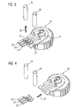
- FIG. 2 shows the volume control module 10 in a state inserted into a housing, wherein the housing itself is not visible. Rather, only two cylindrical fixing pins 19, 20 are shown, which engage in a semi-circular recesses 21, 22 in the printed circuit board 12 in a form-fitting manner.
- the two mounting pins 19 and 20 are perpendicular to the plane of the circuit board 12. Between them run the tracks 16, 17 and 18.
- These are spring contacts 23, 24, 25 contacted, which are formed as forked curved contact tongues.
- the mounting pins 19, 20 are held in the hearing aid housing in corresponding fitting holes. They can be pushed out of these fitting bores along their longitudinal axis without the hearing aid housing having to be opened. Since, however, as in FIG. 2 is shown in the inserted state with the circuit board 12 positively engage, the circuit board 12 and the entire volume control module 10 can not move in the plane of the circuit board 12. The volume control module 10 is thus removably mounted in the hearing aid housing.
- FIG. 3 shows the same volume control module 10 as shown in FIG. 2 is shown. According to the arrow 26, however, the two fixing pins 19, 20 are removed from the housing or from the recesses 21, 22 according to the arrow 26. The volume control module 10 is now movable along the printed circuit board 12. In FIG. 4 is indicated by the arrow 27 that the volume control module 10 is removed from the housing.
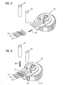
- the volume control module 10 is now replaced by a volume control module 10 'and according to FIG. 5 pushed back into the hearing aid housing, as symbolized by the arrow 28.
- the spring contact tongues 23, 24 and 25 of the hearing device electronics contact the conductor tracks of the volume control module 10 '.
- the last assembly step will now be accordingly FIG. 6 the mounting pins 19 and 20 back into the hearing aid housing, ie its fitted holes inserted, as indicated by arrow 29. They engage in the recesses 21 ', 22' of the circuit board 12 'of the newly inserted volume control module 10'.
- the newly inserted volume control module 10 ' is attached again in the hearing aid housing.
- the replacement of the volume control module thus takes place without soldering and also in particular without a special tool.
Landscapes
- Engineering & Computer Science (AREA)
- Acoustics & Sound (AREA)
- Neurosurgery (AREA)
- Otolaryngology (AREA)
- Physics & Mathematics (AREA)
- General Health & Medical Sciences (AREA)
- Health & Medical Sciences (AREA)
- Signal Processing (AREA)
- Manufacturing & Machinery (AREA)
- Mounting Components In General For Electric Apparatus (AREA)
- Casings For Electric Apparatus (AREA)
- Measurement Of The Respiration, Hearing Ability, Form, And Blood Characteristics Of Living Organisms (AREA)
- Fittings On The Vehicle Exterior For Carrying Loads, And Devices For Holding Or Mounting Articles (AREA)
Claims (7)
- Ecouteur comprenant- un boîtier qui a au moins un évidement, et- un module ( 10 ) de réglage du niveau sonore y compris un élément ( 12 ) de montage et un réglage ( 11 ) du niveau sonore, qui est monté sur l'élément ( 12 ) de montage, le module ( 10 ) de réglage du niveau sonore pouvant être inséré dans le boîtier en pouvant en être retiré,caractérisé en ce que- l'élément ( 12 ) de montage a au moins deux évidements ( 21, 22 ) d'immobilisation et- deux éléments ( 19, 20 ) de broche sont enfilés à complémentarité de forme et avec possibilité d'être retirés dans l'évidement du boîtier et dans les évidements ( 21, 22 ) d'immobilisation de sorte que le module ( 10 ) de réglage du niveau sonore ne peut être retiré du boîtier qu'après avoir retiré les éléments ( 19, 20 ) de broche des évidements ( 21, 22 ) d'immobilisation.
- Ecouteur suivant la revendication 1, dans lequel le module ( 10 ) de réglage du niveau sonore est guidé dans un guidage du boîtier lorsqu'il est inséré et retiré du boîtier à l'aide de l'élément ( 12 ) de montage.
- Ecouteur suivant la revendication 1 ou 2, dans lequel les pistes ( 16, 17, 18 ) conductrices s'étendent entre les deux éléments ( 19, 20 ) de broche.
- Ecouteur suivant la revendication 3, dans lequel le module ( 10 ) de réglage du niveau sonore peut être introduit dans le boîtier suivant une direction d'introduction et les évidement ( 21, 22 ) d'immobilisation associés aux deux éléments de broches sont disposés sur une ligne de liaison transversalement à la direction d'introduction.
- Ecouteur suivant l'une des revendications précédentes 1 ou 2, dans lequel l'élément de montage est une plaquette à circuit imprimé et l'axe longitudinal du au moins un élément ( 19, 20 ) de broche s'étend à l'état inséré perpendiculairement à l'élément ( 12 ) de montage.
- Ecouteur suivant la revendication 5, dans lequel au moins un contact ( 23, 24, 25 ) à ressort d'un dispositif électronique de l'écouteur touche une piste ( 16, 17, 18 ) conductrice de l'élément ( 12 ) de montage lorsque le module ( 10 ) de réglage du niveau sonore est à l'état inséré.
- Ecouteur suivant la revendication 3 et 6, dans lequel le au moins un contact ( 23, 24, 25 ) à ressort pénètre, lorsque le module de réglage du niveau sonore est à l'état inséré, entre les deux éléments (19, 20) de broche.
Applications Claiming Priority (1)
| Application Number | Priority Date | Filing Date | Title |
|---|---|---|---|
| DE102007013419A DE102007013419B3 (de) | 2007-03-20 | 2007-03-20 | Hörvorrichtung mit entnehmbarem Lautstärkestellermodul |
Publications (2)
| Publication Number | Publication Date |
|---|---|
| EP1973376A1 EP1973376A1 (fr) | 2008-09-24 |
| EP1973376B1 true EP1973376B1 (fr) | 2010-05-12 |
Family
ID=39434388
Family Applications (1)
| Application Number | Title | Priority Date | Filing Date |
|---|---|---|---|
| EP08102260A Not-in-force EP1973376B1 (fr) | 2007-03-20 | 2008-03-04 | Dispositif d'écoute doté d'un module de réglage du volume sonore amovible |
Country Status (5)
| Country | Link |
|---|---|
| US (1) | US20080232626A1 (fr) |
| EP (1) | EP1973376B1 (fr) |
| AT (1) | ATE467988T1 (fr) |
| DE (2) | DE102007013419B3 (fr) |
| DK (1) | DK1973376T3 (fr) |
Families Citing this family (2)
| Publication number | Priority date | Publication date | Assignee | Title |
|---|---|---|---|---|
| CN106878896B (zh) * | 2015-09-21 | 2021-03-02 | 奥迪康有限公司 | 听力装置 |
| WO2019070229A1 (fr) * | 2017-10-03 | 2019-04-11 | Honeywell International Inc. | Dispositif et procédé de régulation de l'intensité sonore dans des protège-oreilles à l'aide d'un potentiomètre à l'intérieur d'une roue creuse |
Family Cites Families (7)
| Publication number | Priority date | Publication date | Assignee | Title |
|---|---|---|---|---|
| US2983797A (en) | 1959-04-14 | 1961-05-09 | E A Myers & Son Inc | Hearing aid |
| US5201008A (en) * | 1987-01-27 | 1993-04-06 | Unitron Industries Ltd. | Modular hearing aid with lid hinged to faceplate |
| US5001762A (en) * | 1989-03-31 | 1991-03-19 | Resistance Technology, Inc. | Miniature modular volume control and integrated circuit assembly for use with a hearing air |
| DE4121311C1 (fr) * | 1991-06-27 | 1992-08-13 | Siemens Ag, 8000 Muenchen, De | |
| US5967837A (en) * | 1996-10-01 | 1999-10-19 | Alps Automotive, Inc. | Assembly for connecting an electric/electronic device to a printed circuit board |
| EP1496530B2 (fr) * | 2003-07-08 | 2010-09-22 | Sonion Roskilde A/S | Tableau de commande avec zone d'activation |
| US20070081686A1 (en) * | 2005-10-11 | 2007-04-12 | Hansaton Akustik Gmbh | Hearing aid |
-
2007
- 2007-03-20 DE DE102007013419A patent/DE102007013419B3/de not_active Expired - Fee Related
-
2008
- 2008-03-04 EP EP08102260A patent/EP1973376B1/fr not_active Not-in-force
- 2008-03-04 AT AT08102260T patent/ATE467988T1/de active
- 2008-03-04 DE DE502008000630T patent/DE502008000630D1/de active Active
- 2008-03-04 DK DK08102260.0T patent/DK1973376T3/da active
- 2008-03-17 US US12/077,135 patent/US20080232626A1/en not_active Abandoned
Also Published As
| Publication number | Publication date |
|---|---|
| US20080232626A1 (en) | 2008-09-25 |
| DE102007013419B3 (de) | 2008-07-10 |
| DE502008000630D1 (de) | 2010-06-24 |
| EP1973376A1 (fr) | 2008-09-24 |
| ATE467988T1 (de) | 2010-05-15 |
| DK1973376T3 (da) | 2010-09-13 |
Similar Documents
| Publication | Publication Date | Title |
|---|---|---|
| EP2285136B1 (fr) | Aide auditive dotée d'un écouteur échangeable | |
| EP0591791A1 (fr) | Prothèse auditive programmable | |
| EP1909536A2 (fr) | Appareil auditif derrière l'oreille doté d'un microphone optique externe | |
| EP1962553A2 (fr) | Dispositif auditif doté d'un dispositif de support de batterie fixé magnétiquement | |
| WO2019105949A1 (fr) | Appareil auditif modulaire | |
| DE102009033898B3 (de) | Ladegerät für ein Hörgerät mit elastischen Kontakten | |
| EP2007172B1 (fr) | Petit tuyau de sortie acoustique doté d'une structure à 2 composants | |
| DE102007025936B4 (de) | Hörgerät mit am Gehäuserahmen befestigtem Anschlussstück | |
| EP1993323A1 (fr) | Pièce d'oreille pour un dispositif auditif doté d'une fermeture à baïonnette | |
| DE102016222323A1 (de) | Hörhilfegerät mit Elektronikrahmen und darin integrierter Antenne | |
| EP2569956B1 (fr) | Prothèse auditive comportant un tiroir à pile | |
| EP1959712A2 (fr) | Dispositif auditif doté d'une bobine de compensation auditive | |
| EP2091124A2 (fr) | Appareil de chargement pour un dispositif auditif doté d'un contact de chargement mobile et système d'appareil auditif correspondant | |
| DE102007013419B3 (de) | Hörvorrichtung mit entnehmbarem Lautstärkestellermodul | |
| EP2001265A2 (fr) | Adaptateur d'appareil auditif | |
| EP2373061A1 (fr) | Dispositif auditif doté d'un élément de guidage, notamment un canal acoustique | |
| EP0244671B1 (fr) | Méthode et dispositif pour la réalisation d'une mesure acoustique de comparaison | |
| EP1915029A2 (fr) | Dispositif de montage pour un composant d'un dispositif auditif et procédé correspondant | |
| DE4121311C1 (fr) | ||
| EP2026604A1 (fr) | Compartiment à pile doté de plusieurs bras de saisie et appareil auditif ainsi équipé | |
| DE102010009012A1 (de) | Vorrichtung zum Einsetzen eines Stiftes in ein Hörgerät | |
| DE102007054603B4 (de) | Hörvorrichtung mit gesteuerter Programmierbuchse | |
| EP2592849A2 (fr) | Prothèse auditive avec un compartiment pour batterie | |
| EP3396979B1 (fr) | Procédé de fabrication d'un cadre de support d'un appareil d'aide auditive et cadre de support ainsi qu'appareil d'aide auditive | |
| DE102009006626A1 (de) | Hörgerät mit Leiterplattenschalter |
Legal Events
| Date | Code | Title | Description |
|---|---|---|---|
| PUAI | Public reference made under article 153(3) epc to a published international application that has entered the european phase |
Free format text: ORIGINAL CODE: 0009012 |
|
| AK | Designated contracting states |
Kind code of ref document: A1 Designated state(s): AT BE BG CH CY CZ DE DK EE ES FI FR GB GR HR HU IE IS IT LI LT LU LV MC MT NL NO PL PT RO SE SI SK TR |
|
| AX | Request for extension of the european patent |
Extension state: AL BA MK RS |
|
| 17P | Request for examination filed |
Effective date: 20090105 |
|
| 17Q | First examination report despatched |
Effective date: 20090213 |
|
| AKX | Designation fees paid |
Designated state(s): AT BE BG CH CY CZ DE DK EE ES FI FR GB GR HR HU IE IS IT LI LT LU LV MC MT NL NO PL PT RO SE SI SK TR |
|
| GRAP | Despatch of communication of intention to grant a patent |
Free format text: ORIGINAL CODE: EPIDOSNIGR1 |
|
| GRAC | Information related to communication of intention to grant a patent modified |
Free format text: ORIGINAL CODE: EPIDOSCIGR1 |
|
| GRAS | Grant fee paid |
Free format text: ORIGINAL CODE: EPIDOSNIGR3 |
|
| GRAA | (expected) grant |
Free format text: ORIGINAL CODE: 0009210 |
|
| AK | Designated contracting states |
Kind code of ref document: B1 Designated state(s): AT BE BG CH CY CZ DE DK EE ES FI FR GB GR HR HU IE IS IT LI LT LU LV MC MT NL NO PL PT RO SE SI SK TR |
|
| REG | Reference to a national code |
Ref country code: GB Ref legal event code: FG4D Free format text: NOT ENGLISH |
|
| REG | Reference to a national code |
Ref country code: CH Ref legal event code: NV Representative=s name: SIEMENS SCHWEIZ AG Ref country code: CH Ref legal event code: EP |
|
| REG | Reference to a national code |
Ref country code: IE Ref legal event code: FG4D Free format text: LANGUAGE OF EP DOCUMENT: GERMAN |
|
| REF | Corresponds to: |
Ref document number: 502008000630 Country of ref document: DE Date of ref document: 20100624 Kind code of ref document: P |
|
| REG | Reference to a national code |
Ref country code: NL Ref legal event code: VDEP Effective date: 20100512 |
|
| REG | Reference to a national code |
Ref country code: DK Ref legal event code: T3 |
|
| LTIE | Lt: invalidation of european patent or patent extension |
Effective date: 20100512 |
|
| PG25 | Lapsed in a contracting state [announced via postgrant information from national office to epo] |
Ref country code: LT Free format text: LAPSE BECAUSE OF FAILURE TO SUBMIT A TRANSLATION OF THE DESCRIPTION OR TO PAY THE FEE WITHIN THE PRESCRIBED TIME-LIMIT Effective date: 20100512 Ref country code: NO Free format text: LAPSE BECAUSE OF FAILURE TO SUBMIT A TRANSLATION OF THE DESCRIPTION OR TO PAY THE FEE WITHIN THE PRESCRIBED TIME-LIMIT Effective date: 20100812 Ref country code: SE Free format text: LAPSE BECAUSE OF FAILURE TO SUBMIT A TRANSLATION OF THE DESCRIPTION OR TO PAY THE FEE WITHIN THE PRESCRIBED TIME-LIMIT Effective date: 20100512 Ref country code: NL Free format text: LAPSE BECAUSE OF FAILURE TO SUBMIT A TRANSLATION OF THE DESCRIPTION OR TO PAY THE FEE WITHIN THE PRESCRIBED TIME-LIMIT Effective date: 20100512 Ref country code: ES Free format text: LAPSE BECAUSE OF FAILURE TO SUBMIT A TRANSLATION OF THE DESCRIPTION OR TO PAY THE FEE WITHIN THE PRESCRIBED TIME-LIMIT Effective date: 20100823 |
|
| PG25 | Lapsed in a contracting state [announced via postgrant information from national office to epo] |
Ref country code: HR Free format text: LAPSE BECAUSE OF FAILURE TO SUBMIT A TRANSLATION OF THE DESCRIPTION OR TO PAY THE FEE WITHIN THE PRESCRIBED TIME-LIMIT Effective date: 20100512 Ref country code: SI Free format text: LAPSE BECAUSE OF FAILURE TO SUBMIT A TRANSLATION OF THE DESCRIPTION OR TO PAY THE FEE WITHIN THE PRESCRIBED TIME-LIMIT Effective date: 20100512 Ref country code: LV Free format text: LAPSE BECAUSE OF FAILURE TO SUBMIT A TRANSLATION OF THE DESCRIPTION OR TO PAY THE FEE WITHIN THE PRESCRIBED TIME-LIMIT Effective date: 20100512 Ref country code: IS Free format text: LAPSE BECAUSE OF FAILURE TO SUBMIT A TRANSLATION OF THE DESCRIPTION OR TO PAY THE FEE WITHIN THE PRESCRIBED TIME-LIMIT Effective date: 20100912 Ref country code: FI Free format text: LAPSE BECAUSE OF FAILURE TO SUBMIT A TRANSLATION OF THE DESCRIPTION OR TO PAY THE FEE WITHIN THE PRESCRIBED TIME-LIMIT Effective date: 20100512 |
|
| REG | Reference to a national code |
Ref country code: IE Ref legal event code: FD4D |
|
| PG25 | Lapsed in a contracting state [announced via postgrant information from national office to epo] |
Ref country code: PL Free format text: LAPSE BECAUSE OF FAILURE TO SUBMIT A TRANSLATION OF THE DESCRIPTION OR TO PAY THE FEE WITHIN THE PRESCRIBED TIME-LIMIT Effective date: 20100512 Ref country code: CY Free format text: LAPSE BECAUSE OF FAILURE TO SUBMIT A TRANSLATION OF THE DESCRIPTION OR TO PAY THE FEE WITHIN THE PRESCRIBED TIME-LIMIT Effective date: 20100602 |
|
| PG25 | Lapsed in a contracting state [announced via postgrant information from national office to epo] |
Ref country code: EE Free format text: LAPSE BECAUSE OF FAILURE TO SUBMIT A TRANSLATION OF THE DESCRIPTION OR TO PAY THE FEE WITHIN THE PRESCRIBED TIME-LIMIT Effective date: 20100512 Ref country code: IE Free format text: LAPSE BECAUSE OF FAILURE TO SUBMIT A TRANSLATION OF THE DESCRIPTION OR TO PAY THE FEE WITHIN THE PRESCRIBED TIME-LIMIT Effective date: 20100512 |
|
| PG25 | Lapsed in a contracting state [announced via postgrant information from national office to epo] |
Ref country code: CZ Free format text: LAPSE BECAUSE OF FAILURE TO SUBMIT A TRANSLATION OF THE DESCRIPTION OR TO PAY THE FEE WITHIN THE PRESCRIBED TIME-LIMIT Effective date: 20100512 Ref country code: SK Free format text: LAPSE BECAUSE OF FAILURE TO SUBMIT A TRANSLATION OF THE DESCRIPTION OR TO PAY THE FEE WITHIN THE PRESCRIBED TIME-LIMIT Effective date: 20100512 Ref country code: RO Free format text: LAPSE BECAUSE OF FAILURE TO SUBMIT A TRANSLATION OF THE DESCRIPTION OR TO PAY THE FEE WITHIN THE PRESCRIBED TIME-LIMIT Effective date: 20100512 |
|
| PLBE | No opposition filed within time limit |
Free format text: ORIGINAL CODE: 0009261 |
|
| STAA | Information on the status of an ep patent application or granted ep patent |
Free format text: STATUS: NO OPPOSITION FILED WITHIN TIME LIMIT |
|
| PG25 | Lapsed in a contracting state [announced via postgrant information from national office to epo] |
Ref country code: IT Free format text: LAPSE BECAUSE OF FAILURE TO SUBMIT A TRANSLATION OF THE DESCRIPTION OR TO PAY THE FEE WITHIN THE PRESCRIBED TIME-LIMIT Effective date: 20100512 |
|
| 26N | No opposition filed |
Effective date: 20110215 |
|
| PG25 | Lapsed in a contracting state [announced via postgrant information from national office to epo] |
Ref country code: GR Free format text: LAPSE BECAUSE OF FAILURE TO SUBMIT A TRANSLATION OF THE DESCRIPTION OR TO PAY THE FEE WITHIN THE PRESCRIBED TIME-LIMIT Effective date: 20100813 |
|
| REG | Reference to a national code |
Ref country code: DE Ref legal event code: R097 Ref document number: 502008000630 Country of ref document: DE Effective date: 20110214 |
|
| BERE | Be: lapsed |
Owner name: SIEMENS AUDIOLOGISCHE TECHNIK G.M.B.H. Effective date: 20110331 |
|
| PG25 | Lapsed in a contracting state [announced via postgrant information from national office to epo] |
Ref country code: MC Free format text: LAPSE BECAUSE OF NON-PAYMENT OF DUE FEES Effective date: 20110331 |
|
| PG25 | Lapsed in a contracting state [announced via postgrant information from national office to epo] |
Ref country code: MT Free format text: LAPSE BECAUSE OF FAILURE TO SUBMIT A TRANSLATION OF THE DESCRIPTION OR TO PAY THE FEE WITHIN THE PRESCRIBED TIME-LIMIT Effective date: 20100512 Ref country code: BE Free format text: LAPSE BECAUSE OF NON-PAYMENT OF DUE FEES Effective date: 20110331 |
|
| PG25 | Lapsed in a contracting state [announced via postgrant information from national office to epo] |
Ref country code: DE Free format text: LAPSE BECAUSE OF NON-PAYMENT OF DUE FEES Effective date: 20111001 |
|
| PGFP | Annual fee paid to national office [announced via postgrant information from national office to epo] |
Ref country code: FR Payment date: 20120327 Year of fee payment: 5 |
|
| PGFP | Annual fee paid to national office [announced via postgrant information from national office to epo] |
Ref country code: DE Payment date: 20110520 Year of fee payment: 4 |
|
| PGFP | Annual fee paid to national office [announced via postgrant information from national office to epo] |
Ref country code: GB Payment date: 20120312 Year of fee payment: 5 Ref country code: DK Payment date: 20120322 Year of fee payment: 5 |
|
| REG | Reference to a national code |
Ref country code: CH Ref legal event code: PL |
|
| PG25 | Lapsed in a contracting state [announced via postgrant information from national office to epo] |
Ref country code: LI Free format text: LAPSE BECAUSE OF NON-PAYMENT OF DUE FEES Effective date: 20120331 Ref country code: CH Free format text: LAPSE BECAUSE OF NON-PAYMENT OF DUE FEES Effective date: 20120331 |
|
| REG | Reference to a national code |
Ref country code: DE Ref legal event code: R119 Ref document number: 502008000630 Country of ref document: DE Effective date: 20121002 |
|
| PG25 | Lapsed in a contracting state [announced via postgrant information from national office to epo] |
Ref country code: LU Free format text: LAPSE BECAUSE OF NON-PAYMENT OF DUE FEES Effective date: 20110304 |
|
| PG25 | Lapsed in a contracting state [announced via postgrant information from national office to epo] |
Ref country code: PT Free format text: LAPSE BECAUSE OF NON-PAYMENT OF DUE FEES Effective date: 20100512 |
|
| PG25 | Lapsed in a contracting state [announced via postgrant information from national office to epo] |
Ref country code: TR Free format text: LAPSE BECAUSE OF FAILURE TO SUBMIT A TRANSLATION OF THE DESCRIPTION OR TO PAY THE FEE WITHIN THE PRESCRIBED TIME-LIMIT Effective date: 20100512 Ref country code: BG Free format text: LAPSE BECAUSE OF FAILURE TO SUBMIT A TRANSLATION OF THE DESCRIPTION OR TO PAY THE FEE WITHIN THE PRESCRIBED TIME-LIMIT Effective date: 20100812 |
|
| REG | Reference to a national code |
Effective date: 20130331 Ref country code: DK Ref legal event code: EBP |
|
| PG25 | Lapsed in a contracting state [announced via postgrant information from national office to epo] |
Ref country code: HU Free format text: LAPSE BECAUSE OF FAILURE TO SUBMIT A TRANSLATION OF THE DESCRIPTION OR TO PAY THE FEE WITHIN THE PRESCRIBED TIME-LIMIT Effective date: 20100512 |
|
| GBPC | Gb: european patent ceased through non-payment of renewal fee |
Effective date: 20130304 |
|
| REG | Reference to a national code |
Ref country code: FR Ref legal event code: ST Effective date: 20131129 |
|
| PG25 | Lapsed in a contracting state [announced via postgrant information from national office to epo] |
Ref country code: FR Free format text: LAPSE BECAUSE OF NON-PAYMENT OF DUE FEES Effective date: 20130402 Ref country code: GB Free format text: LAPSE BECAUSE OF NON-PAYMENT OF DUE FEES Effective date: 20130304 |
|
| PG25 | Lapsed in a contracting state [announced via postgrant information from national office to epo] |
Ref country code: DK Free format text: LAPSE BECAUSE OF NON-PAYMENT OF DUE FEES Effective date: 20130331 |
|
| REG | Reference to a national code |
Ref country code: AT Ref legal event code: MM01 Ref document number: 467988 Country of ref document: AT Kind code of ref document: T Effective date: 20130304 |
|
| PG25 | Lapsed in a contracting state [announced via postgrant information from national office to epo] |
Ref country code: AT Free format text: LAPSE BECAUSE OF NON-PAYMENT OF DUE FEES Effective date: 20130304 |