EP1973708B1 - Greifer zum greifen einer kolben-baugruppe - Google Patents
Greifer zum greifen einer kolben-baugruppe Download PDFInfo
- Publication number
- EP1973708B1 EP1973708B1 EP07716703.9A EP07716703A EP1973708B1 EP 1973708 B1 EP1973708 B1 EP 1973708B1 EP 07716703 A EP07716703 A EP 07716703A EP 1973708 B1 EP1973708 B1 EP 1973708B1
- Authority
- EP
- European Patent Office
- Prior art keywords
- piston
- gripper
- robot
- subassembly
- connecting rod
- Prior art date
- Legal status (The legal status is an assumption and is not a legal conclusion. Google has not performed a legal analysis and makes no representation as to the accuracy of the status listed.)
- Active
Links
Images


Classifications
-
- B—PERFORMING OPERATIONS; TRANSPORTING
- B23—MACHINE TOOLS; METAL-WORKING NOT OTHERWISE PROVIDED FOR
- B23P—METAL-WORKING NOT OTHERWISE PROVIDED FOR; COMBINED OPERATIONS; UNIVERSAL MACHINE TOOLS
- B23P19/00—Machines for simply fitting together or separating metal parts or objects, or metal and non-metal parts, whether or not involving some deformation; Tools or devices therefor so far as not provided for in other classes
- B23P19/04—Machines for simply fitting together or separating metal parts or objects, or metal and non-metal parts, whether or not involving some deformation; Tools or devices therefor so far as not provided for in other classes for assembling or disassembling parts
- B23P19/042—Machines for simply fitting together or separating metal parts or objects, or metal and non-metal parts, whether or not involving some deformation; Tools or devices therefor so far as not provided for in other classes for assembling or disassembling parts specially adapted for combustion engines
- B23P19/043—Machines for simply fitting together or separating metal parts or objects, or metal and non-metal parts, whether or not involving some deformation; Tools or devices therefor so far as not provided for in other classes for assembling or disassembling parts specially adapted for combustion engines for inserting piston-connecting rods assemblies in cylinders
-
- B—PERFORMING OPERATIONS; TRANSPORTING
- B25—HAND TOOLS; PORTABLE POWER-DRIVEN TOOLS; MANIPULATORS
- B25J—MANIPULATORS; CHAMBERS PROVIDED WITH MANIPULATION DEVICES
- B25J9/00—Program-controlled manipulators
- B25J9/0084—Program-controlled manipulators comprising a plurality of manipulators
-
- B—PERFORMING OPERATIONS; TRANSPORTING
- B25—HAND TOOLS; PORTABLE POWER-DRIVEN TOOLS; MANIPULATORS
- B25J—MANIPULATORS; CHAMBERS PROVIDED WITH MANIPULATION DEVICES
- B25J9/00—Program-controlled manipulators
- B25J9/16—Program controls
- B25J9/1679—Program controls characterised by the tasks executed
- B25J9/1682—Dual arm manipulator; Coordination of several manipulators
-
- Y—GENERAL TAGGING OF NEW TECHNOLOGICAL DEVELOPMENTS; GENERAL TAGGING OF CROSS-SECTIONAL TECHNOLOGIES SPANNING OVER SEVERAL SECTIONS OF THE IPC; TECHNICAL SUBJECTS COVERED BY FORMER USPC CROSS-REFERENCE ART COLLECTIONS [XRACs] AND DIGESTS
- Y10—TECHNICAL SUBJECTS COVERED BY FORMER USPC
- Y10T—TECHNICAL SUBJECTS COVERED BY FORMER US CLASSIFICATION
- Y10T29/00—Metal working
- Y10T29/49—Method of mechanical manufacture
- Y10T29/49229—Prime mover or fluid pump making
- Y10T29/49231—I.C. [internal combustion] engine making
- Y10T29/49233—Repairing, converting, servicing or salvaging
-
- Y—GENERAL TAGGING OF NEW TECHNOLOGICAL DEVELOPMENTS; GENERAL TAGGING OF CROSS-SECTIONAL TECHNOLOGIES SPANNING OVER SEVERAL SECTIONS OF THE IPC; TECHNICAL SUBJECTS COVERED BY FORMER USPC CROSS-REFERENCE ART COLLECTIONS [XRACs] AND DIGESTS
- Y10—TECHNICAL SUBJECTS COVERED BY FORMER USPC
- Y10T—TECHNICAL SUBJECTS COVERED BY FORMER US CLASSIFICATION
- Y10T29/00—Metal working
- Y10T29/49—Method of mechanical manufacture
- Y10T29/49229—Prime mover or fluid pump making
- Y10T29/49249—Piston making
-
- Y—GENERAL TAGGING OF NEW TECHNOLOGICAL DEVELOPMENTS; GENERAL TAGGING OF CROSS-SECTIONAL TECHNOLOGIES SPANNING OVER SEVERAL SECTIONS OF THE IPC; TECHNICAL SUBJECTS COVERED BY FORMER USPC CROSS-REFERENCE ART COLLECTIONS [XRACs] AND DIGESTS
- Y10—TECHNICAL SUBJECTS COVERED BY FORMER USPC
- Y10T—TECHNICAL SUBJECTS COVERED BY FORMER US CLASSIFICATION
- Y10T29/00—Metal working
- Y10T29/49—Method of mechanical manufacture
- Y10T29/49998—Work holding
-
- Y—GENERAL TAGGING OF NEW TECHNOLOGICAL DEVELOPMENTS; GENERAL TAGGING OF CROSS-SECTIONAL TECHNOLOGIES SPANNING OVER SEVERAL SECTIONS OF THE IPC; TECHNICAL SUBJECTS COVERED BY FORMER USPC CROSS-REFERENCE ART COLLECTIONS [XRACs] AND DIGESTS
- Y10—TECHNICAL SUBJECTS COVERED BY FORMER USPC
- Y10T—TECHNICAL SUBJECTS COVERED BY FORMER US CLASSIFICATION
- Y10T29/00—Metal working
- Y10T29/53—Means to assemble or disassemble
- Y10T29/53039—Means to assemble or disassemble with control means energized in response to activator stimulated by condition sensor
- Y10T29/53061—Responsive to work or work-related machine element
- Y10T29/53078—Responsive to work or work-related machine element with means to fasten by frictional fitting
-
- Y—GENERAL TAGGING OF NEW TECHNOLOGICAL DEVELOPMENTS; GENERAL TAGGING OF CROSS-SECTIONAL TECHNOLOGIES SPANNING OVER SEVERAL SECTIONS OF THE IPC; TECHNICAL SUBJECTS COVERED BY FORMER USPC CROSS-REFERENCE ART COLLECTIONS [XRACs] AND DIGESTS
- Y10—TECHNICAL SUBJECTS COVERED BY FORMER USPC
- Y10T—TECHNICAL SUBJECTS COVERED BY FORMER US CLASSIFICATION
- Y10T29/00—Metal working
- Y10T29/53—Means to assemble or disassemble
- Y10T29/5313—Means to assemble electrical device
- Y10T29/53261—Means to align and advance work part
-
- Y—GENERAL TAGGING OF NEW TECHNOLOGICAL DEVELOPMENTS; GENERAL TAGGING OF CROSS-SECTIONAL TECHNOLOGIES SPANNING OVER SEVERAL SECTIONS OF THE IPC; TECHNICAL SUBJECTS COVERED BY FORMER USPC CROSS-REFERENCE ART COLLECTIONS [XRACs] AND DIGESTS
- Y10—TECHNICAL SUBJECTS COVERED BY FORMER USPC
- Y10T—TECHNICAL SUBJECTS COVERED BY FORMER US CLASSIFICATION
- Y10T29/00—Metal working
- Y10T29/53—Means to assemble or disassemble
- Y10T29/53313—Means to interrelatedly feed plural work parts from plural sources without manual intervention
- Y10T29/53365—Multiple station assembly apparatus
-
- Y—GENERAL TAGGING OF NEW TECHNOLOGICAL DEVELOPMENTS; GENERAL TAGGING OF CROSS-SECTIONAL TECHNOLOGIES SPANNING OVER SEVERAL SECTIONS OF THE IPC; TECHNICAL SUBJECTS COVERED BY FORMER USPC CROSS-REFERENCE ART COLLECTIONS [XRACs] AND DIGESTS
- Y10—TECHNICAL SUBJECTS COVERED BY FORMER USPC
- Y10T—TECHNICAL SUBJECTS COVERED BY FORMER US CLASSIFICATION
- Y10T29/00—Metal working
- Y10T29/53—Means to assemble or disassemble
- Y10T29/53904—Means comprising piston ring group contractor or holder
-
- Y—GENERAL TAGGING OF NEW TECHNOLOGICAL DEVELOPMENTS; GENERAL TAGGING OF CROSS-SECTIONAL TECHNOLOGIES SPANNING OVER SEVERAL SECTIONS OF THE IPC; TECHNICAL SUBJECTS COVERED BY FORMER USPC CROSS-REFERENCE ART COLLECTIONS [XRACs] AND DIGESTS
- Y10—TECHNICAL SUBJECTS COVERED BY FORMER USPC
- Y10T—TECHNICAL SUBJECTS COVERED BY FORMER US CLASSIFICATION
- Y10T29/00—Metal working
- Y10T29/53—Means to assemble or disassemble
- Y10T29/53961—Means to assemble or disassemble with work-holder for assembly
-
- Y—GENERAL TAGGING OF NEW TECHNOLOGICAL DEVELOPMENTS; GENERAL TAGGING OF CROSS-SECTIONAL TECHNOLOGIES SPANNING OVER SEVERAL SECTIONS OF THE IPC; TECHNICAL SUBJECTS COVERED BY FORMER USPC CROSS-REFERENCE ART COLLECTIONS [XRACs] AND DIGESTS
- Y10—TECHNICAL SUBJECTS COVERED BY FORMER USPC
- Y10T—TECHNICAL SUBJECTS COVERED BY FORMER US CLASSIFICATION
- Y10T29/00—Metal working
- Y10T29/53—Means to assemble or disassemble
- Y10T29/53991—Work gripper, anvil, or element
Definitions
- This invention relates to a gripper for gripping a piston subassembly comprising a connecting rod and a piston bead provided with one or more rings according to the preamble of claim 1.
- a gripper is known from US 2004/0194296 .
- Programmable robots are commonly used for a variety of repetitive industrial applications. Painting, welding, dispensing and material handling are examples of typical applications. For processes with high complexity and precision requirements such as engine piston stuffing, manual work and use of dedicated automation equipment are still dominant.
- U.S. Patent No. 6,047,472 discloses a method and apparatus for use of industrial robots in engine piston stuffing to transport the piston with connecting rod, to put the cap on the connecting rod, and to run down the cap with screws.
- the piston inserting process is still performed with a dedicated automation machine that requires a level of precision and tolerance that limits its application.
- US patent application No..2004/0194296 discloses an automatic piston inserting equipment comprising: block positioning means for positioning a cylinder block to a piston insertion position; piston position means for moving and positioning a piston into a cylinder bore in the cylinder block; cap positioning means for moving and positioning a connecting rod cap; and clamping means for clamping the connecting rod cap to the piston inserted into the cylinder bore.
- US patent application No.2003/167628 discloses an automatic piston installation apparatus comprising: a block positioning mechanism for positioning a cylinder block in a working area; a piston positioning mechanism for positioning a piston at an insertion position; a piston inserting mechanism for inserting the piston into a cylinder bore; a cap positioning mechanism for positioning a connecting rod cap to a fastening position; and a fastening mechanism for fastening the connecting rod cap to the piston inserted into the cylinder bore.
- Patent DE3715405 discloses an apparatus for controlling the assembly of a piston in a cylinder, having gripping fingers and associated accelerometers. The accelerometers are connected by lines to a testing device suitable to detect defective assembly and piston ring breakages.
- US patent application No.2001/024044 discloses a work chuck/inserting apparatus for chucking a work piece and inserting it into an insertion hole; the apparatus includes three or more chuck fingers and a tracer mechanism to control such fingers.
- a gripper for gripping a piston subassembly comprises a connecting rod and a piston head provided with one or more rings, wherein the gripper comprises a detection unit for detecting the presence of the one or more rings.
- the gripper comprises a pushing/suction unit for picking up the piston subassembly, the pushing/suction unit comprising a suction cup mounted on a pusher, and the pusher being extendable outwardly from the gripper for picking the piston subassembly.
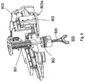
- a first robot 100 with its fixture 101 also shown in more detail as 702 in Fig. 7 , picks up the engine block 102, also shown in more detail in Fig. 7 , from a pallet. While the pallet is not shown in Fig. 1 it is similar to pallet 400 shown in Fig. 2 and can be a pallet on a conveyor system or transported by a robot or other means.
- Robot 100 moves the picked up engine block 102 to a position close to the second robot 200 and orients the engine block 102 so, as is described below, the second and third robots 200 and 300, respectively, can perform the piston stuffing.
- the combination of the engine block 102 and fixture 101 are shown as 1002 in Fig. 10 .
- An external axis in the form of a motor 702a of Fig. 7 controlled by the robot controller not shown in Fig. 1 but well known to those of ordinary skill in the art rotates the crankshaft (not shown) of the engine block 102 to the right orientation for the piston to be stuffed in an associated one of the three cylinder bores 701c of Fig. 7 in the first row 701a of Fig. 7 of cylinder bores in engine block 102.
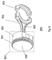
- the assembly 600 has a ring 601, a piston skirt 602, a connecting rod 603 with a groove 605, a connecting rod cap 604 and a piston head 606.
- the ring 601, piston skirt 602, connecting rod 603 and head 606 are assembled elsewhere prior to the stuffing of the piston in one of the cylinder bores 701c and are delivered to the stuffing workstation with an unattached associated connecting rod cap 604.
- the stuffing operation consists of stuffing the ring, skirt, connecting rod and head combination, referred to hereinafter as subassembly 607, into one of the bores 701c and then attaching the associated connecting rod cap 604 to subassembly 607.
- Robot 200 which has force control, moves its uniquely designed gripper 201, which is shown in detail in Fig. 8 as 800, onto a piston subassembly 607, which is shown in detail in Fig. 6 and just below the gripper in Fig. 8 .
- the gripper 201 has jaws 801 to grab the piston subassembly 607. Before the jaws 801 are closed to grab the piston subassembly 607, the gripper 201 sucks up the piston subassembly 607 using a suction cup 902 of Fig. 9 on a pusher 901 of Fig. 9 against the upper surface of the piston head 606.
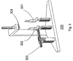
- robot 300 using the guiding pins and cap placing gripper 301 shown in Fig. 3 picks up the connecting rod cap 604 of piston assembly 600, moves it under the engine block 102 and protrudes the guiding pins 301 through the crankshaft and the cylinder bore of the engine block 102 to receive the piston connecting rod 604.
- Robot 200 moves the gripper 201 with the piston subassembly 607 inserted therein (see Figs. 8 and 10 for that,combination) above the cylinder bore 701c to be stuffed and then moves the piston subassembly 607 into the bore 701c to engage the connecting rod 603, leading the tips of the guiding pins 301 into the screw holes most clearly shown in Fig.
- a stabilizing finger 803 in Fig. 8 is employed to keep the connecting rod 603 in place during transportation of the piston subassembly 607 to the cylinder bore 701c from the pallet where the piston subassembly 607 is gripped by the robot 200.
- Robot 200 and robot 300 move cooperatively until the lower surface of the piston skirt 602 in Fig. 6 is close to the upper surface 701b of the cylinder bore 701c into which the piston subassembly 607 is to be inserted. Then robot 200 enables its active searching function, that is, its force control functionality, to move the subassembly 607 so that the piston skirt 602 finds that cylinder bore 701c and the piston subassembly 607 is inserted in that bore until the lower surface 807 in Fig. 8 of the gripper jaws 801 touch the upper surface 701b of the cylinder bore. Next, the piston assembly 600 is pushed further into the cylinder bore.
- active searching function that is, its force control functionality
- the third robot 300 with its connecting rod cap placing and rundown device 302, and also shown in more detail as 1001 in Fig. 10 , places the connecting rod cap 604 of Fig. 6 and screws on the inserted piston subassembly 607 and fastens the cap 604 onto the connecting rod 603. The same process is repeated for subsequent cylinder bores in the first row 701a of Fig. 7 of three cylinder bores 701c for this V-6 engine block 102.
- robot 100 After the stuffing is finished for the first row 701a of cylinder bores 701c, robot 100 reorients the engine block 102 so that the upper surface of the other row of three cylinder bores (not shown in the figures for the V6 engine) can be stuffed.
- the piston stuffing procedure described above for the first row 701a is repeated to stuff a piston assembly 600 into each of the cylinder bores 701c in the second row.
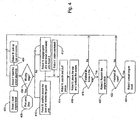
- Fig. 4 which is described below, shows a process flow diagram for the piston stuffing technique using three robots.
- the second robot 200 picks up a piston subassembly 607 consisting of a piston and a connecting rod cap 604, and puts the cap 604 into the cap feeder 303 in Fig. 3 .
- Robot 100 with its tool 702 picks up an engine block 102 from the pallet 400 in Fig. 2 which can be on a conveyor or transported by a robot or other means and moves it to above the guiding pins 301 in Fig. 3 of the stationary tools and orients the engine block so that robot 200 can perform the piston stuffing.
- an external axis rotates the crankshaft using crankshaft rotating motor 702a to the right orientation for the cylinder bore 701c to be stuffed in an associated one of the three cylinder bores 701c in the first row 701a of cylinder bores 701c.
- the guide pins 301 move up and protrude through the crankshaft and the cylinder bore 701c to receive the piston connecting rod 603 while robot 200 moves its gripper with the piston subassembly 607 to above the cylinder bore 701c to be stuffed and moves down vertically to engage the connecting rod upper half bearing with the guiding pins 301, letting the tips of the guiding pins into the screw holes 806 on the connecting rod 603.
- the stabilizing finger 803 of Fig. 8 is employed to keep the connecting rod 603 in place during transportation of the piston subassembly 607 to the cylinder bore 701c from the pallet 400 where piston subassembly 607 is gripped by the robot 100.
- Robot 200 and the guide pin assembly 301 move down until the lower surface of the piston skirt 602 is above but very close to the cylinder bore upper surface 701b. Then robot 200 enables its active searching function, that is its force control functionality, to move the subassembly 607 so that the piston skirt 602 finds the cylinder bore 701c and the piston subassembly 607 is inserted in that bore until the lower surface of the gripper jaws 801 touch the upper surface 701b of the cylinder bore 701c.
- active searching function that is its force control functionality
- the piston subassembly 607 is further pushed into the cylinder bore 701c.
- the gripper 800 retracts its pusher, leaves the engine block 102 and moves to the pallet 400 to pick up the next piston subassembly 607 and its cap 604 and places the cap 604 onto the cap feeder 303 while robot 100 moves the stuffed cylinder bore to the cap rundown station 302.
- a pusher 304 on the stationary tool set 300 comes down to maintain the position of the piston subassembly 607 inside the cylinder bore during the time the tool places the cap 604 on and fastens the screws.
- robot 100 moves the second cylinder bore 701c to above the guide pins 301.
- the same stuffing process described above for the first cylinder bore 701c is repeated for the second and third cylinder bores 701c in the first row 701a of the engine block 102.
- the same procedure as that described above, for the first row 701a of cylinder bores 701c in engine block 102 is used to stuff the pistons in the second row of cylinder bores 701c in the engine block 102.
- Fig. 5 which is described below, illustrates the process flow diagram for piston stuffing with two robots and the set of stationary tools 300 shown in Fig. 3 .
- the piston stuffing gripper 800 shown in Figs. 8 and 9 consists of gripper jaws 801; gripper jaw driving unit 805 which is driven by air pressure from a suitable source (not shown) under control of the robot controller; enforcement ring and driving unit 802; rod stabilization finger assembly 803 of Fig. 8 and 904 of Fig. 9 ; pushing/suction unit 901 and 902 of Fig. 9 ; and piston ring detection unit, one embodiment for which is shown in Fig. 11 and is described below.
- a built-in pusher 900 with a suction cup 902 the suction device for which is not shown in Fig.
- Gripper jaws 801 close and clamp the piston subassembly 607 when the subassembly is in position.
- An enforcement ring 802 slides down to lock the gripper jaws 801 in position.
- the rod-stabilizing finger 803/904 comes down and its fingertip 803a/904a will push into the groove 605 on the connecting rod 603 from one side to secure the connecting rod 603, preventing it from swinging during the transportation of the piston subassembly 607 from the pallet 400 to the cylinder bore 701c of the engine block 102.
- the finger 803/904 moves up to get out of the way so that the connecting rod 603 can insert further into the cylinder bore 701c.
- the jaws 801 grip both the piston rings 601 shown in Fig. 6 the skirt 602 to ensure that the piston subassembly 607 is firmly gripped. Before pushing the piston subassembly 607 into the cylinder bore 701c, the jaws 801 are released.
- the enforcement ring 802 limits the outward movement of the jaws 801 and leaves a small but necessary gap between the piston skirt outer surface and the jaws' inner surface, letting the piston subassembly 607 be pushed easily through the cylinder bore 701c.
- the pusher 901 will stay at the extended position while the connecting cap 604 is put on and screws are rundown in the three-robot piston stuffing solution.
- the pusher 901 will retract after pushing the piston subassembly 607 in position and a locking pusher 304 in Fig. 3 on the stationary tools 300 is used to keep the piston 600 in place during cap placing and screw run down.
- a ring detection unit 1100 of Fig. 11 is built in the gripper jaws 801.
- Fig. 11 illustrates the ring detection unit 1100 and its principle of operation.
- a ring-detecting sensor such as a proximity switch 1103 and 1104 is used to detect the presence of a ring 1102, normally iron based material.
- the associated proximity switch 1103, 1104 is triggered and the light associated with that switch is on as is shown in Fig. 11 by way of example for switch 1103. If as is shown in Fig. 11 by way of example for the lowest groove in piston 1101, a ring does not exist in that groove the proximity switch 1104 remains off and the associated light is off. In this way, the sensors 1103 and 1104 determine the presence of the rings 1102 in the grooves before the piston subassembly 607 is stuffed into bore 701c.
- the ring detection circuitry 1100 can be connected into the controller of robot 200 as a digital input to indicate the ring presence.
- a chart 1105 shows the correlation between sensing distance and size of the sensing object for a typical proximity sensor.
- a torque/force sensor is mounted on the robot wrist to provide a force measurement to the robot controller.
- a velocity, that is, force, controller which may be part of the robot controller generates an attraction force vector which is superimposed on the measured force in a preferred direction and orientation.
- the force vector may also be a repulsive force vector as the same may be needed during the mating of the piston subassembly 607 with the associated one of the cylinder bores 701c and the -force provided by the vector whether it is that of attraction or repulsion need not be constant.
- the attraction force vector is imposed on the robot drive so that the robot stuffing gripper 800 which holds the piston subassembly 607 is subject to a force which may be constant, that is, the absolute value of the vector.
- a force which may be constant that is, the absolute value of the vector.
- a search velocity force pattern in a plane parallel to that surface is superimposed by the controller with the velocity force command to the robot gripper 800.
- An example of the search pattern might be a circular motion or a spiral motion in a plane parallel to the surface to cover the possible location of the bore hole 701c that is to receive the subassembly 607.
- the piston subassembly 607 will find the bore 701c and the attraction force will drag the gripper 800 and thus the subassembly 607 downward so that the subassembly can be inserted in the associated bore 701c seamlessly with the gripper jaw's lower surface 708 against the engine block's upper surface 701b.
- the search range should be selected to cover the maximum possible uncertainty in the location of the associated bore 701c on the surface of the engine block 102 that has in it the cylinder bores 701c.
- force control is activated when the lower surface of the piston skirt 602 is close to but not touching the cylinder bore upper surface 701b.
- a downward retention force valued about 40N is set and certain search patterns such as spiral and circular can be used.
- the first search finish condition is set as the piston subassembly 607 is inserted into the cylinder bore 701c for a certain distance, such as 3 millimeters. Then the downward retention force increases to a higher value, such as 260 N. This force will "drag" the piston subassembly 607 further into the bore 701c until the lower surface of the gripper jaws 801 touch the upper surface 701b of the cylinder bore 701c.
- the piston subassembly 607 is further pushed by the pusher cylinder 901 into the cylinder bore 701c to engage with the crankshaft.
- the same retention force, 260N keeps the lower surface of the gripper jaws 801 in contact with the upper surface 701b of the cylinder bore 701c.
- Fig. 4 shows a process flow diagram for the piston stuffing technique using three robots. That process starts at 402 where robot 100 loads the engine block 102. At 404, robot 200 loads the piston subassembly 607 and robot 300 picks up the connecting rod cap 604 of the piston assembly 600 and the screws for attaching , cap 604 to the upper part of the assembly 600. At 406, the ring detection unit 1100 built into the gripper jaws 801 determines if any rings are missing from the piston subassembly 607. If any rings are missing the process stops at 408.
- robot 200 positions the piston subassembly 607 above the bore 701c in the engine block 102 into which the subassembly is to be stuffed and receives the guide pins 301.
- robot 300 at 412 engages the guide pins 301 and moves coordinately with robot 200.
- robot 100 rotates the crankshaft of the engine block 102 to the right orientation for the piston subassembly 607 to be stuffed in an associated one of the three cylinder bores 701c in the first row 701a of cylinder bores in the engine block 102.
- robot 200 After robot 200 moves down until the lower surface of the piston skirt 602 is above but very close to the cylinder bore upper surface 701b, robot 200 enables at 414 its active searching function, that is its force control functionality, to move the subassembly 607 so that the piston skirt 602 finds the cylinder bore 701c and the piston subassembly 607 is inserted in that bore until the lower surface of the gripper jaws 801 touch the upper surface 701b of the cylinder bore. At 416, robot 300 places the cap 604 on the upper portion of the piston assembly 600 and fastens it in place by tightening the screws.
- its active searching function that is its force control functionality
- the method determines if all of the bores 701c in the first row 701a of bores in the V6 engine block 102 of this example have been stuffed with piston assemblies 600 as described above. If the answer is no, then the method returns to 404 so that a piston subassembly 607 can be stuffed in each of the remaining cylinder bores 701c in row 701a. If the answer is yes, then at 420 the engine block 102 is reoriented so that the next row of cylinder bores 701c can be stuffed with piston subassemblies 607. At 422, the method determines if all of the rows in the engine block 102 are stuffed with piston assemblies 600.
- the engine block 102 with all of its cylinder bores stuffed with piston assemblies 600 is unloaded by robot 100. If not, then the method returns to 404 so that a piston subassembly 607 can be stuffed in each of the remaining cylinder bores 701c in that row.
- Fig. 5 shows a process flow diagram for the piston stuffing technique using two robots 100 and 200 and a set of stationary tools 300. That process starts at 502 where robot 200 loads the piston subassembly 607 and the connecting rod cap 604 of the piston assembly 600. At 504, robot 100 loads the engine block 102. At 506, the ring detection unit 1100 built into the gripper jaws 801 determines if any rings are missing from the piston subassembly 607. If any rings are missing the process stops at 508.
- robot 200 places the cap 604 on the cap feeder 303 and at 512 robot 100 positions the engine block 102 above the station for the guide pins 301 and rotates the crankshaft of the engine block 102 so that to the right orientation for the piston subassembly 607 to be stuffed in an associated one of the cylinder bores 701c in the engine block.
- the cap feeder 303 feeds the cap 604 to the rundown station 302.
- robot 200 After robot 200 and guide pin assembly 301 moves down until the lower surface of the piston skirt 602 is above but very close to the cylinder bore upper surface 701b, robot 200 enables at 516 its active searching function, that is its force control functionality, to move the subassembly 607 so that the piston skirt 602 finds the cylinder bore 701c and the piston subassembly 607 is inserted in that bore until the lower surface of the gripper jaws 801 touch the upper surface 701b of the cylinder bore 701c.
- robot 100 moves the stuffed cylinder bore 701c to the cap rundown station 302.
- the pusher 304 on the stationary tool set 300 comes down to maintain the position of the piston subassembly 607 inside the cylinder bore during the time the tool places the cap 604 on and fastens the screws.
- the method determines if all of the bores 701c in the engine block 102 have been stuffed with piston assemblies 600 as described above. If the answer is no, then the method returns to 502 but robot 100 does not at 504 have to load another engine block 102 as the present engine block 102 does not have all of its cylinders stuffed with piston assemblies 600. If the answer is yes, then at 524 robot 100 unloads the engine block 102.
- a robot which is force controlled to with the force control search and insert, that is, stuff, a piston subassembly with compressed rings in an cylinder bore of an engine block thereby eliminating the need for extreme precision in the positioning of the block or piston; and put a rod cap and screws on the connecting rod of the subassembly and rundown the screws and may use another robot to position the engine block, and yet another robot may be used to mount a placing gripper for the rod cap and pins which is used to guide the coupling between the rod cap and the connecting rod; 2) the robot has a gripper that picks up the piston, compresses the rings, stabilizes the connection rod, and further pushes the piston into its final position; 3) the presence or absence of a piston ring can be easily detected by using a detector built into the robot gripper; and 4) can be used on any block configuration, namely in-line, v-block and deep-skirted v-block engines, to accommodate different production rates by addition of robots
Landscapes
- Engineering & Computer Science (AREA)
- Mechanical Engineering (AREA)
- Robotics (AREA)
- Chemical & Material Sciences (AREA)
- Combustion & Propulsion (AREA)
- Automatic Assembly (AREA)
Claims (8)
- Greifer (800) zum Greifen einer Kolben-Untergruppe (607), die eine Verbindungsstange (603) und einen Kolbenboden (606) aufweist, der über einen oder mehrere Ringe (601, 602) verfügt, wobei der Greifer (800) eine Erfassungseinheit (1100) zum Erfassen des Vorhandenseins des einen oder der mehreren Ringe (601, 1102) aufweist, dadurch gekennzeichnet, dass er eine Drück-/Saug-Einheit (901, 902) zum Aufnehmen der Kolben-Untergruppe (607) aufweist, wobei die Drück-/Saug-Einheit eine Saugglocke (902) aufweist, die auf einem Drücker (901) befestigt ist, und wobei der Drücker (901) von dem Greifer aus nach außen verlängerbar ist, um die Kolben-Untergruppe aufzunehmen.
- Greifer (800) nach Anspruch 1, aufweisend eine oder mehrere Backen (801) zum Greifen der Kolben-Untergruppe (607), und wobei die Erfassungseinheit (1100) in die eine oder die mehreren Backen (801) eingebaut ist.
- Greifer (800) nach Anspruch 1, wobei die Erfassungseinheit (1100) zumindest einen Ring-erfassenden Sensor aufweist, der einem Erfassungsindikator zugeordnet ist.
- Greifer (800) nach Anspruch 3, wobei der zumindest eine Ring-erfassende Sensor einen Näherungsschalter (1103, 1104) aufweist.
- Greifer (800) nach Anspruch 1, ferner aufweisend einen Stabilisator (803), der geeignet ist, mit der Kolben-Untergruppe (607) zu interagieren, um die Position der Verbindungsstange während der Bewegung zu stabilisieren.
- Greifer (201, 800) nach Anspruch 1, ferner aufweisend einen Verstärkungsring und eine Antriebseinheit (802) zum Einrasten der Backen (801), wenn die Kolben-Untergruppe (607) gegriffen wird.
- Roboter (200) zum Einführen einer Kolbengruppe (600) in eine entsprechende Bohrung (701c) eines Motorblocks (102, 701), wobei die Kolbengruppe (600) Folgendes aufweist:einen Stangendeckel (604); undeine Kolben-Untergruppe (607), die eine Verbindungsstange (603), die geeignet ist, eine Verbindung zu dem Stangendeckel (604) herzustellen, und einen Kolbenboden (606), der mit einem oder mehreren Ringen (601, 1102) versehen ist, aufweist, dadurch gekennzeichnet, dass sie einen Greifer (201, 800) nach einem der Ansprüche 1 bis 6 aufweist.
- Roboter (200) nach Anspruch 7, ferner aufweisend eine Kraftsteuerung zum Regulieren der Kraft, die während der Bewegung der Kolben-Untergruppe (607) ausgeübt wird, wobei die Kraftsteuerung den Roboter (200) veranlasst, während der Bewegung der Kolben-Untergruppe (607) eine Suche durchzuführen, um die Bohrung (701c) zu finden.
Applications Claiming Priority (2)
| Application Number | Priority Date | Filing Date | Title |
|---|---|---|---|
| US75986506P | 2006-01-18 | 2006-01-18 | |
| PCT/US2007/001194 WO2007084536A1 (en) | 2006-01-18 | 2007-01-17 | Method and apparatus for engine piston installation by use of industrial robots |
Publications (2)
| Publication Number | Publication Date |
|---|---|
| EP1973708A1 EP1973708A1 (de) | 2008-10-01 |
| EP1973708B1 true EP1973708B1 (de) | 2016-08-10 |
Family
ID=38042646
Family Applications (2)
| Application Number | Title | Priority Date | Filing Date |
|---|---|---|---|
| EP07716720.3A Active EP1973693B1 (de) | 2006-01-18 | 2007-01-17 | Verfahren und vorrichtung für motorkolbenmontage mittels industrieroboter |
| EP07716703.9A Active EP1973708B1 (de) | 2006-01-18 | 2007-01-17 | Greifer zum greifen einer kolben-baugruppe |
Family Applications Before (1)
| Application Number | Title | Priority Date | Filing Date |
|---|---|---|---|
| EP07716720.3A Active EP1973693B1 (de) | 2006-01-18 | 2007-01-17 | Verfahren und vorrichtung für motorkolbenmontage mittels industrieroboter |
Country Status (4)
| Country | Link |
|---|---|
| US (3) | US8667657B2 (de) |
| EP (2) | EP1973693B1 (de) |
| CN (2) | CN101410227B (de) |
| WO (2) | WO2007084536A1 (de) |
Families Citing this family (38)
| Publication number | Priority date | Publication date | Assignee | Title |
|---|---|---|---|---|
| DE102010010718A1 (de) * | 2010-03-09 | 2011-09-15 | Kuka Laboratories Gmbh | Verfahren zur Montage von Bauteilen mittels eines Industrieroboters |
| JP5653073B2 (ja) * | 2010-05-19 | 2015-01-14 | キヤノン株式会社 | ロボットセル装置及び生産システム |
| JP5085749B2 (ja) * | 2011-02-21 | 2012-11-28 | ファナック株式会社 | 棒状部材の搬送装置 |
| WO2012143969A1 (ja) * | 2011-04-19 | 2012-10-26 | 平田機工株式会社 | ピストン供給装置及びピストン供給方法 |
| CN102218652B (zh) * | 2011-05-09 | 2012-11-21 | 无锡引域智能机器人有限公司 | 一种利用机器人的柔顺性实现轴孔装配的装置和方法 |
| CN103182643B (zh) * | 2011-12-30 | 2016-06-15 | 江苏林海动力机械集团公司 | 发动机活塞分装装配工装 |
| CN102528729B (zh) * | 2012-01-06 | 2014-08-27 | 重庆小康工业集团股份有限公司 | 发动机连杆盖装配工装 |
| JP6039187B2 (ja) * | 2012-02-03 | 2016-12-07 | キヤノン株式会社 | 組立装置、把持ハンドおよび物品の組立方法 |
| WO2013190648A1 (ja) * | 2012-06-20 | 2013-12-27 | 株式会社安川電機 | ロボットシステムおよび部品の製造方法 |
| US9092698B2 (en) | 2012-06-21 | 2015-07-28 | Rethink Robotics, Inc. | Vision-guided robots and methods of training them |
| CN103624538A (zh) * | 2012-08-21 | 2014-03-12 | 安徽华菱汽车有限公司 | 发动机装配工艺 |
| US9579806B2 (en) | 2012-08-23 | 2017-02-28 | Rethink Robotics, Inc. | Robotic power and signal distribution using laminated cable with separator webs |
| US9085080B2 (en) * | 2012-12-06 | 2015-07-21 | International Business Machines Corp. | Human augmentation of robotic work |
| CN103085064A (zh) * | 2013-01-16 | 2013-05-08 | 华东理工大学 | 自组装机器人和自组装机器人组装方法 |
| JP5884785B2 (ja) * | 2013-07-30 | 2016-03-15 | 株式会社安川電機 | ロボット |
| KR101550609B1 (ko) * | 2013-12-30 | 2015-09-08 | 현대자동차 주식회사 | 엔진용 피스톤 어셈블리 장착장치 |
| US9523328B2 (en) | 2014-02-26 | 2016-12-20 | Ford Global Technologies, Llc | System, method and tooling for flexible assembly of cylinder-head valve trains |
| CN104308486B (zh) * | 2014-07-23 | 2017-06-13 | 大连豪森瑞德设备制造有限公司 | 多品种大型发动机活塞环装配机 |
| CN105773133A (zh) * | 2016-03-07 | 2016-07-20 | 成都亨通兆业精密机械有限公司 | 自动装配系统 |
| US10265814B2 (en) | 2016-06-28 | 2019-04-23 | Ford Motor Company | Flexible pressing system |
| US10534350B2 (en) | 2016-06-28 | 2020-01-14 | Ford Motor Company | Flexible pressing verification system |
| US10315280B2 (en) | 2016-06-28 | 2019-06-11 | Ford Motor Company | Integrated robotic press and reaction frame |
| US20170368763A1 (en) | 2016-06-28 | 2017-12-28 | Ford Motor Company | Applicator and Method for Applying a Lubricant/Sealer |
| CN106737811A (zh) * | 2016-12-28 | 2017-05-31 | 中国科学院自动化研究所 | 用于抓取活塞的机械手 |
| CN107414872B (zh) * | 2017-05-12 | 2024-03-26 | 河南森源电气股份有限公司 | 箱体夹具及使用该夹具的机械手装置 |
| DE102017209402A1 (de) * | 2017-06-02 | 2018-12-06 | Thyssenkrupp Ag | Greifvorrichtung für Kolben |
| DE102017119489A1 (de) * | 2017-08-25 | 2019-02-28 | Kuka Systems Gmbh | Positionier- und Spannsystem und Verfahren |
| CN108086151B (zh) * | 2017-12-21 | 2023-09-08 | 香港中文大学(深圳) | 一种变径夹持装置 |
| CN108274294A (zh) * | 2017-12-29 | 2018-07-13 | 科大天工智能装备技术(天津)有限公司 | 一种3d打印数控机床上下料装置及其使用方法 |
| CN108655726B (zh) * | 2018-05-21 | 2019-07-19 | 广东科捷龙机器人有限公司 | 基于机器视觉识别的机械手抓取装配控制系统 |
| CN108723758B (zh) * | 2018-07-02 | 2024-01-12 | 珠海市英诚电子科技有限公司 | 打螺母机 |
| US11034024B2 (en) * | 2019-02-15 | 2021-06-15 | GM Global Technology Operations LLC | Fixtureless component assembly |
| CN111185933B (zh) * | 2020-02-25 | 2022-11-15 | 洛阳理工学院 | 一种配电柜夹层板夹持机械手 |
| US20220176564A1 (en) * | 2020-12-04 | 2022-06-09 | GM Global Technology Operations LLC | Accurate position control for fixtureless assembly |
| KR20220170297A (ko) * | 2021-06-22 | 2022-12-29 | 현대자동차주식회사 | 피스톤 삽입장치 및 그 방법 |
| CN113369853B (zh) * | 2021-08-04 | 2022-10-04 | 威海新光电碳制品有限公司 | 一种堵帽安装装置及安装方法 |
| CN117124056B (zh) * | 2023-07-24 | 2025-09-26 | 中国航空工业集团公司北京长城航空测控技术研究所 | 多机器人协同柔性药柱组件装配系统及其装配方法 |
| CN118927252B (zh) * | 2024-08-28 | 2025-02-18 | 盐城工学院 | 一种汽车门板组装机械手的协同控制方法 |
Citations (1)
| Publication number | Priority date | Publication date | Assignee | Title |
|---|---|---|---|---|
| US5953804A (en) * | 1998-07-10 | 1999-09-21 | Systems Engineering Company | Automated workpiece insertion method and apparatus |
Family Cites Families (29)
| Publication number | Priority date | Publication date | Assignee | Title |
|---|---|---|---|---|
| US1741110A (en) * | 1929-01-23 | 1929-12-24 | Paul W Heinrich | Piston-ring setter |
| CA1007428A (en) * | 1974-01-17 | 1977-03-29 | Itt Canada Limited | Machine and method for assembling pistons into engines |
| JPS58186536A (ja) | 1982-04-26 | 1983-10-31 | Aisin Seiki Co Ltd | 自動組付装置 |
| US4591198A (en) * | 1984-02-16 | 1986-05-27 | Monforte Robotics, Inc. | Robotic end effectors |
| JPS62148127A (ja) | 1985-12-20 | 1987-07-02 | N K Ii:Kk | ピストンリングの嵌入装置 |
| GB2197228A (en) * | 1986-11-14 | 1988-05-18 | Ford Motor Co | Method of assembling components |
| US4918991A (en) | 1986-12-01 | 1990-04-24 | Westinghouse Electric Corp. | Method for sampling nuclear fuel pellets with a robot gripper mechanism |
| DE3715405A1 (de) | 1987-05-08 | 1988-11-17 | Messerschmitt Boelkow Blohm | Vorrichtung zum ueberpruefen der automatischen montage eines kolbens |
| US4858974A (en) * | 1988-05-02 | 1989-08-22 | Stannek Karl H | Robotic gripper head |
| DE3937570A1 (de) * | 1989-11-11 | 1991-05-29 | Claus Schmidt | Spannfutter |
| DE4211069A1 (de) | 1992-04-03 | 1993-10-07 | Daimler Benz Ag | Fertigungs- oder Montagelinie |
| JPH0788794A (ja) | 1993-09-21 | 1995-04-04 | Nissan Motor Co Ltd | 組付本体に対する組付部品の組付方法及び同方法に使用する産業用ロボット |
| US5471738A (en) * | 1993-10-04 | 1995-12-05 | Ford Motor Company | Robotic system for inserting cylinder liners into internal combustion engine cylinder blocks |
| US5987726A (en) | 1996-03-11 | 1999-11-23 | Fanuc Robotics North America, Inc. | Programmable positioner for the stress-free assembly of components |
| DE19713996C2 (de) * | 1997-04-04 | 1999-04-22 | Abb Patent Gmbh | Vorrichtung zum Einbau einer aus Kolben und Pleuelstange bestehenden Baugruppe eines Verbrennungsmotors |
| SE511704C2 (sv) | 1998-03-19 | 1999-11-08 | Saab Ab | Förfarande och anordning för montering av vinge |
| FR2784043B1 (fr) * | 1998-10-02 | 2000-10-27 | Renault | Procede et dispositif d'emmanchement d'un ensemble bielle-axe-piston dans un carter cylindre |
| JP2001246591A (ja) | 2000-03-06 | 2001-09-11 | Fuji Photo Film Co Ltd | 組立ロボット |
| JP4439751B2 (ja) * | 2000-03-15 | 2010-03-24 | 平田機工株式会社 | 被挿入物の把持・挿入装置、被挿入物の把持・挿入方法および組立ユニット |
| US6941645B2 (en) | 2000-03-15 | 2005-09-13 | Kazuhiro Kosuge | Automatic piston inserting equipment using a vision system |
| US6467155B1 (en) * | 2000-06-29 | 2002-10-22 | Caterpillar Inc | Transfer control system for piston insertion machine |
| US6367141B1 (en) * | 2000-06-29 | 2002-04-09 | Caterpillar Inc. | Method of inserting a piston assembly into a cylinder of an internal combustion engine |
| US6591484B2 (en) * | 2001-06-14 | 2003-07-15 | Caterpillar Inc | Internal combustion engine piston insertion machine |
| US6627016B2 (en) | 2001-10-25 | 2003-09-30 | Abb, Inc. (Flexible Automation Division) | Robotic assembly process for plastic components |
| JP4063557B2 (ja) * | 2002-03-11 | 2008-03-19 | 平田機工株式会社 | ピストン自動組付け装置 |
| US6658713B1 (en) * | 2002-10-29 | 2003-12-09 | General Motors Corporation | Semi-automatic engine piston assembly tool |
| US7181314B2 (en) | 2003-11-24 | 2007-02-20 | Abb Research Ltd. | Industrial robot with controlled flexibility and simulated force for automated assembly |
| US7146724B2 (en) * | 2004-01-30 | 2006-12-12 | General Motors Corporation | Method of Assembling an internal combustion engine |
| KR100863095B1 (ko) * | 2007-08-28 | 2008-10-13 | 기아자동차주식회사 | 엔진의 피스톤 조립 공법 시스템 |
-
2007
- 2007-01-16 US US11/653,566 patent/US8667657B2/en not_active Expired - Fee Related
- 2007-01-16 US US11/653,716 patent/US8079143B2/en active Active
- 2007-01-17 WO PCT/US2007/001194 patent/WO2007084536A1/en not_active Ceased
- 2007-01-17 WO PCT/US2007/001218 patent/WO2007084551A1/en not_active Ceased
- 2007-01-17 CN CN2007800024061A patent/CN101410227B/zh active Active
- 2007-01-17 EP EP07716720.3A patent/EP1973693B1/de active Active
- 2007-01-17 CN CN2007800024362A patent/CN101389445B/zh active Active
- 2007-01-17 EP EP07716703.9A patent/EP1973708B1/de active Active
-
2011
- 2011-10-07 US US13/268,044 patent/US20120036692A1/en not_active Abandoned
Patent Citations (1)
| Publication number | Priority date | Publication date | Assignee | Title |
|---|---|---|---|---|
| US5953804A (en) * | 1998-07-10 | 1999-09-21 | Systems Engineering Company | Automated workpiece insertion method and apparatus |
Also Published As
| Publication number | Publication date |
|---|---|
| US20070163107A1 (en) | 2007-07-19 |
| US20120036692A1 (en) | 2012-02-16 |
| CN101389445A (zh) | 2009-03-18 |
| CN101389445B (zh) | 2012-04-11 |
| WO2007084551A1 (en) | 2007-07-26 |
| US8667657B2 (en) | 2014-03-11 |
| EP1973708A1 (de) | 2008-10-01 |
| EP1973693B1 (de) | 2015-06-03 |
| CN101410227B (zh) | 2013-05-01 |
| CN101410227A (zh) | 2009-04-15 |
| US20070169231A1 (en) | 2007-07-19 |
| EP1973693A1 (de) | 2008-10-01 |
| WO2007084536A1 (en) | 2007-07-26 |
| US8079143B2 (en) | 2011-12-20 |
Similar Documents
| Publication | Publication Date | Title |
|---|---|---|
| EP1973708B1 (de) | Greifer zum greifen einer kolben-baugruppe | |
| US9329585B2 (en) | Article assembling device using robot | |
| CN1233510C (zh) | 物件搬运装置 | |
| US20010024044A1 (en) | Work chucking/inserting apparatus and assembling unit | |
| CN208841003U (zh) | 一种智能夹持棒料机构 | |
| US11126155B2 (en) | Automatic screw inspection system | |
| US10183366B2 (en) | Feeder mechanism for feeding mechanical fasteners | |
| WO2023220193A1 (en) | Method and system for determining a workpiece loading location in a cnc machine with a robotic arm | |
| CN115241781A (zh) | 一种控制柜或电气柜背板装配生产线及其装配工艺 | |
| JP2009241254A (ja) | 被挿入物の把持・挿入装置および被挿入物の把持・挿入方法 | |
| US6783484B2 (en) | Machine tool with gripper and/ or tool magazine system | |
| US7062999B2 (en) | Inverted vertical lathe | |
| Zhang et al. | Automated engine piston installation using industrial robots | |
| CN218051265U (zh) | 一种精密装配件的机器人配件自动装配系统 | |
| CN217626249U (zh) | 一种通用型自动化上下料装置 | |
| CN114619465B (zh) | 一种机器人夹具的抓取控制方法 | |
| CN112810032B (zh) | 一种用于装配五金件和密封圈的工件加工设备及工艺 | |
| JP2001179677A (ja) | ビンピッキング装置 | |
| CN220313380U (zh) | 用于环形结构件的自动化机加工生产线 | |
| CN110449998A (zh) | 一种钻头研磨设备用上下料装置 | |
| CN119871062B (zh) | 一种用于汽车零部件的机械手 | |
| CN223114634U (zh) | 发动机缸盖夹具 | |
| TWI861970B (zh) | 機械人、機械人系統及機械人之作業方法 | |
| CN216577915U (zh) | 一种适用于环形物料抓取的柔性装置 | |
| CN108204924B (zh) | 一种拔取力与嵌合长度全自动检测方法 |
Legal Events
| Date | Code | Title | Description |
|---|---|---|---|
| PUAI | Public reference made under article 153(3) epc to a published international application that has entered the european phase |
Free format text: ORIGINAL CODE: 0009012 |
|
| 17P | Request for examination filed |
Effective date: 20080801 |
|
| AK | Designated contracting states |
Kind code of ref document: A1 Designated state(s): AT BE BG CH CY CZ DE DK EE ES FI FR GB GR HU IE IS IT LI LT LU LV MC NL PL PT RO SE SI SK TR |
|
| 17Q | First examination report despatched |
Effective date: 20120306 |
|
| DAX | Request for extension of the european patent (deleted) | ||
| GRAP | Despatch of communication of intention to grant a patent |
Free format text: ORIGINAL CODE: EPIDOSNIGR1 |
|
| RIC1 | Information provided on ipc code assigned before grant |
Ipc: B25J 15/00 20060101AFI20160209BHEP Ipc: B25J 9/00 20060101ALI20160209BHEP Ipc: B25J 13/08 20060101ALI20160209BHEP Ipc: F02F 7/00 20060101ALI20160209BHEP Ipc: B23P 19/04 20060101ALI20160209BHEP Ipc: B25J 9/16 20060101ALI20160209BHEP |
|
| INTG | Intention to grant announced |
Effective date: 20160302 |
|
| GRAS | Grant fee paid |
Free format text: ORIGINAL CODE: EPIDOSNIGR3 |
|
| GRAA | (expected) grant |
Free format text: ORIGINAL CODE: 0009210 |
|
| AK | Designated contracting states |
Kind code of ref document: B1 Designated state(s): AT BE BG CH CY CZ DE DK EE ES FI FR GB GR HU IE IS IT LI LT LU LV MC NL PL PT RO SE SI SK TR |
|
| REG | Reference to a national code |
Ref country code: GB Ref legal event code: FG4D |
|
| REG | Reference to a national code |
Ref country code: CH Ref legal event code: EP Ref country code: AT Ref legal event code: REF Ref document number: 818549 Country of ref document: AT Kind code of ref document: T Effective date: 20160815 |
|
| REG | Reference to a national code |
Ref country code: IE Ref legal event code: FG4D |
|
| REG | Reference to a national code |
Ref country code: DE Ref legal event code: R096 Ref document number: 602007047363 Country of ref document: DE |
|
| REG | Reference to a national code |
Ref country code: LT Ref legal event code: MG4D |
|
| REG | Reference to a national code |
Ref country code: NL Ref legal event code: MP Effective date: 20160810 |
|
| REG | Reference to a national code |
Ref country code: AT Ref legal event code: MK05 Ref document number: 818549 Country of ref document: AT Kind code of ref document: T Effective date: 20160810 |
|
| PG25 | Lapsed in a contracting state [announced via postgrant information from national office to epo] |
Ref country code: IT Free format text: LAPSE BECAUSE OF FAILURE TO SUBMIT A TRANSLATION OF THE DESCRIPTION OR TO PAY THE FEE WITHIN THE PRESCRIBED TIME-LIMIT Effective date: 20160810 Ref country code: NL Free format text: LAPSE BECAUSE OF FAILURE TO SUBMIT A TRANSLATION OF THE DESCRIPTION OR TO PAY THE FEE WITHIN THE PRESCRIBED TIME-LIMIT Effective date: 20160810 Ref country code: IS Free format text: LAPSE BECAUSE OF FAILURE TO SUBMIT A TRANSLATION OF THE DESCRIPTION OR TO PAY THE FEE WITHIN THE PRESCRIBED TIME-LIMIT Effective date: 20161210 Ref country code: FI Free format text: LAPSE BECAUSE OF FAILURE TO SUBMIT A TRANSLATION OF THE DESCRIPTION OR TO PAY THE FEE WITHIN THE PRESCRIBED TIME-LIMIT Effective date: 20160810 Ref country code: LT Free format text: LAPSE BECAUSE OF FAILURE TO SUBMIT A TRANSLATION OF THE DESCRIPTION OR TO PAY THE FEE WITHIN THE PRESCRIBED TIME-LIMIT Effective date: 20160810 |
|
| PG25 | Lapsed in a contracting state [announced via postgrant information from national office to epo] |
Ref country code: SE Free format text: LAPSE BECAUSE OF FAILURE TO SUBMIT A TRANSLATION OF THE DESCRIPTION OR TO PAY THE FEE WITHIN THE PRESCRIBED TIME-LIMIT Effective date: 20160810 Ref country code: ES Free format text: LAPSE BECAUSE OF FAILURE TO SUBMIT A TRANSLATION OF THE DESCRIPTION OR TO PAY THE FEE WITHIN THE PRESCRIBED TIME-LIMIT Effective date: 20160810 Ref country code: AT Free format text: LAPSE BECAUSE OF FAILURE TO SUBMIT A TRANSLATION OF THE DESCRIPTION OR TO PAY THE FEE WITHIN THE PRESCRIBED TIME-LIMIT Effective date: 20160810 Ref country code: PT Free format text: LAPSE BECAUSE OF FAILURE TO SUBMIT A TRANSLATION OF THE DESCRIPTION OR TO PAY THE FEE WITHIN THE PRESCRIBED TIME-LIMIT Effective date: 20161212 Ref country code: GR Free format text: LAPSE BECAUSE OF FAILURE TO SUBMIT A TRANSLATION OF THE DESCRIPTION OR TO PAY THE FEE WITHIN THE PRESCRIBED TIME-LIMIT Effective date: 20161111 Ref country code: LV Free format text: LAPSE BECAUSE OF FAILURE TO SUBMIT A TRANSLATION OF THE DESCRIPTION OR TO PAY THE FEE WITHIN THE PRESCRIBED TIME-LIMIT Effective date: 20160810 Ref country code: PL Free format text: LAPSE BECAUSE OF FAILURE TO SUBMIT A TRANSLATION OF THE DESCRIPTION OR TO PAY THE FEE WITHIN THE PRESCRIBED TIME-LIMIT Effective date: 20160810 |
|
| PG25 | Lapsed in a contracting state [announced via postgrant information from national office to epo] |
Ref country code: EE Free format text: LAPSE BECAUSE OF FAILURE TO SUBMIT A TRANSLATION OF THE DESCRIPTION OR TO PAY THE FEE WITHIN THE PRESCRIBED TIME-LIMIT Effective date: 20160810 Ref country code: RO Free format text: LAPSE BECAUSE OF FAILURE TO SUBMIT A TRANSLATION OF THE DESCRIPTION OR TO PAY THE FEE WITHIN THE PRESCRIBED TIME-LIMIT Effective date: 20160810 |
|
| REG | Reference to a national code |
Ref country code: DE Ref legal event code: R097 Ref document number: 602007047363 Country of ref document: DE |
|
| PG25 | Lapsed in a contracting state [announced via postgrant information from national office to epo] |
Ref country code: SK Free format text: LAPSE BECAUSE OF FAILURE TO SUBMIT A TRANSLATION OF THE DESCRIPTION OR TO PAY THE FEE WITHIN THE PRESCRIBED TIME-LIMIT Effective date: 20160810 Ref country code: BG Free format text: LAPSE BECAUSE OF FAILURE TO SUBMIT A TRANSLATION OF THE DESCRIPTION OR TO PAY THE FEE WITHIN THE PRESCRIBED TIME-LIMIT Effective date: 20161110 Ref country code: DK Free format text: LAPSE BECAUSE OF FAILURE TO SUBMIT A TRANSLATION OF THE DESCRIPTION OR TO PAY THE FEE WITHIN THE PRESCRIBED TIME-LIMIT Effective date: 20160810 Ref country code: CZ Free format text: LAPSE BECAUSE OF FAILURE TO SUBMIT A TRANSLATION OF THE DESCRIPTION OR TO PAY THE FEE WITHIN THE PRESCRIBED TIME-LIMIT Effective date: 20160810 Ref country code: BE Free format text: LAPSE BECAUSE OF FAILURE TO SUBMIT A TRANSLATION OF THE DESCRIPTION OR TO PAY THE FEE WITHIN THE PRESCRIBED TIME-LIMIT Effective date: 20160810 |
|
| PLBE | No opposition filed within time limit |
Free format text: ORIGINAL CODE: 0009261 |
|
| STAA | Information on the status of an ep patent application or granted ep patent |
Free format text: STATUS: NO OPPOSITION FILED WITHIN TIME LIMIT |
|
| 26N | No opposition filed |
Effective date: 20170511 |
|
| PG25 | Lapsed in a contracting state [announced via postgrant information from national office to epo] |
Ref country code: SI Free format text: LAPSE BECAUSE OF FAILURE TO SUBMIT A TRANSLATION OF THE DESCRIPTION OR TO PAY THE FEE WITHIN THE PRESCRIBED TIME-LIMIT Effective date: 20160810 |
|
| REG | Reference to a national code |
Ref country code: CH Ref legal event code: PL |
|
| PG25 | Lapsed in a contracting state [announced via postgrant information from national office to epo] |
Ref country code: MC Free format text: LAPSE BECAUSE OF FAILURE TO SUBMIT A TRANSLATION OF THE DESCRIPTION OR TO PAY THE FEE WITHIN THE PRESCRIBED TIME-LIMIT Effective date: 20160810 |
|
| REG | Reference to a national code |
Ref country code: FR Ref legal event code: ST Effective date: 20170929 |
|
| PG25 | Lapsed in a contracting state [announced via postgrant information from national office to epo] |
Ref country code: CH Free format text: LAPSE BECAUSE OF NON-PAYMENT OF DUE FEES Effective date: 20170131 Ref country code: LI Free format text: LAPSE BECAUSE OF NON-PAYMENT OF DUE FEES Effective date: 20170131 Ref country code: FR Free format text: LAPSE BECAUSE OF NON-PAYMENT OF DUE FEES Effective date: 20170131 |
|
| REG | Reference to a national code |
Ref country code: IE Ref legal event code: MM4A |
|
| PG25 | Lapsed in a contracting state [announced via postgrant information from national office to epo] |
Ref country code: LU Free format text: LAPSE BECAUSE OF NON-PAYMENT OF DUE FEES Effective date: 20170117 |
|
| PG25 | Lapsed in a contracting state [announced via postgrant information from national office to epo] |
Ref country code: IE Free format text: LAPSE BECAUSE OF NON-PAYMENT OF DUE FEES Effective date: 20170117 |
|
| PG25 | Lapsed in a contracting state [announced via postgrant information from national office to epo] |
Ref country code: HU Free format text: LAPSE BECAUSE OF FAILURE TO SUBMIT A TRANSLATION OF THE DESCRIPTION OR TO PAY THE FEE WITHIN THE PRESCRIBED TIME-LIMIT; INVALID AB INITIO Effective date: 20070117 |
|
| PG25 | Lapsed in a contracting state [announced via postgrant information from national office to epo] |
Ref country code: CY Free format text: LAPSE BECAUSE OF NON-PAYMENT OF DUE FEES Effective date: 20160810 |
|
| REG | Reference to a national code |
Ref country code: DE Ref legal event code: R082 Ref document number: 602007047363 Country of ref document: DE Representative=s name: KUHNEN & WACKER PATENT- UND RECHTSANWALTSBUERO, DE Ref country code: DE Ref legal event code: R081 Ref document number: 602007047363 Country of ref document: DE Owner name: MCGILLIS, DANIEL W., FRASER, US Free format text: FORMER OWNERS: ABB RESEARCH LTD., ZUERICH, CH; MCGILLIS, DANIEL W., FRASER, MICH., US Ref country code: DE Ref legal event code: R081 Ref document number: 602007047363 Country of ref document: DE Owner name: ABB SCHWEIZ AG, CH Free format text: FORMER OWNERS: ABB RESEARCH LTD., ZUERICH, CH; MCGILLIS, DANIEL W., FRASER, MICH., US |
|
| REG | Reference to a national code |
Ref country code: GB Ref legal event code: 732E Free format text: REGISTERED BETWEEN 20200206 AND 20200212 |
|
| PG25 | Lapsed in a contracting state [announced via postgrant information from national office to epo] |
Ref country code: TR Free format text: LAPSE BECAUSE OF FAILURE TO SUBMIT A TRANSLATION OF THE DESCRIPTION OR TO PAY THE FEE WITHIN THE PRESCRIBED TIME-LIMIT Effective date: 20160810 |
|
| PGFP | Annual fee paid to national office [announced via postgrant information from national office to epo] |
Ref country code: DE Payment date: 20250121 Year of fee payment: 19 |
|
| PGFP | Annual fee paid to national office [announced via postgrant information from national office to epo] |
Ref country code: GB Payment date: 20250128 Year of fee payment: 19 |