EP1973807B1 - Vorrichtung zum schutz einer flüssigkeit vor der darüberliegenden atmosphäre in einem behälter mit hals - Google Patents
Vorrichtung zum schutz einer flüssigkeit vor der darüberliegenden atmosphäre in einem behälter mit hals Download PDFInfo
- Publication number
- EP1973807B1 EP1973807B1 EP06842279A EP06842279A EP1973807B1 EP 1973807 B1 EP1973807 B1 EP 1973807B1 EP 06842279 A EP06842279 A EP 06842279A EP 06842279 A EP06842279 A EP 06842279A EP 1973807 B1 EP1973807 B1 EP 1973807B1
- Authority
- EP
- European Patent Office
- Prior art keywords
- tubular body
- receptacle
- fact
- neck
- distinguished
- Prior art date
- Legal status (The legal status is an assumption and is not a legal conclusion. Google has not performed a legal analysis and makes no representation as to the accuracy of the status listed.)
- Not-in-force
Links
- 239000007788 liquid Substances 0.000 title claims abstract description 40
- 239000000463 material Substances 0.000 claims abstract description 8
- 230000002093 peripheral effect Effects 0.000 claims description 3
- 239000011324 bead Substances 0.000 claims 1
- 239000012528 membrane Substances 0.000 description 7
- 239000000047 product Substances 0.000 description 7
- 208000031968 Cadaver Diseases 0.000 description 4
- 238000000605 extraction Methods 0.000 description 3
- 235000014101 wine Nutrition 0.000 description 3
- 238000009434 installation Methods 0.000 description 2
- 230000003647 oxidation Effects 0.000 description 2
- 238000007254 oxidation reaction Methods 0.000 description 2
- 230000001681 protective effect Effects 0.000 description 2
- QVGXLLKOCUKJST-UHFFFAOYSA-N atomic oxygen Chemical compound [O] QVGXLLKOCUKJST-UHFFFAOYSA-N 0.000 description 1
- 230000035622 drinking Effects 0.000 description 1
- 235000013305 food Nutrition 0.000 description 1
- 239000012263 liquid product Substances 0.000 description 1
- 238000004519 manufacturing process Methods 0.000 description 1
- 210000000056 organ Anatomy 0.000 description 1
- 229910052760 oxygen Inorganic materials 0.000 description 1
- 239000001301 oxygen Substances 0.000 description 1
- 239000003973 paint Substances 0.000 description 1
- 239000002245 particle Substances 0.000 description 1
- 235000011837 pasties Nutrition 0.000 description 1
- 235000015096 spirit Nutrition 0.000 description 1
- 235000015041 whisky Nutrition 0.000 description 1
Images


Classifications
-
- B—PERFORMING OPERATIONS; TRANSPORTING
- B65—CONVEYING; PACKING; STORING; HANDLING THIN OR FILAMENTARY MATERIAL
- B65D—CONTAINERS FOR STORAGE OR TRANSPORT OF ARTICLES OR MATERIALS, e.g. BAGS, BARRELS, BOTTLES, BOXES, CANS, CARTONS, CRATES, DRUMS, JARS, TANKS, HOPPERS, FORWARDING CONTAINERS; ACCESSORIES, CLOSURES, OR FITTINGS THEREFOR; PACKAGING ELEMENTS; PACKAGES
- B65D81/00—Containers, packaging elements, or packages, for contents presenting particular transport or storage problems, or adapted to be used for non-packaging purposes after removal of contents
- B65D81/24—Adaptations for preventing deterioration or decay of contents; Applications to the container or packaging material of food preservatives, fungicides, pesticides or animal repellants
- B65D81/245—Internal membrane, floating cover or the like isolating the contents from the ambient atmosphere
Definitions
- the present invention relates to improvements made in the field of the protection of liquids contained in neck containers in order to protect them from damage to the atmosphere which surmounts them in the containers, and in particular oxidation due to oxygen. air enclosed in partially filled containers. This may include the protection of drinking liquids, such as wines and spirits.
- the object of the invention is essentially, knowing the state of the art mentioned above, to propose a practical technical solution capable of protecting a liquid contained in a neck container whatever the level of the liquid in said container while leaving all freedom to pour the liquid by inclination of the container.
- the discoidal element can rest on the free surface of the liquid by accompanying the variations of level thereof in the container and the device, its shutter member being removed, allowed the free discharge of the liquid out of the inclined container.
- the portion of the tubular body which is underlying said upper mounting portion has a length that the discoidal element, collected around the tubular body when the introduction of the device through the neck of a container, can unfold freely in the body of the container once the device in position in the container.
- the tubular body is radially deformable or, preferably, that the portion of the tubular body that underlies said upper mounting portion has a diameter substantially less than that of said upper mounting portion: an annular space is thus left free between the tubular body and the wall of the neck of the container during the introduction of the device through the neck of a container, annular space which is adapted to receive the discoidal element picked up around the tubular body.
- the portion of the tubular body which is underlying said upper mounting portion is substantially conical frustoconical turned towards the lower end of the tubular body.
- the upper mounting portion of the tubular body is adapted to cooperate sealingly with the neck of the container, and for this purpose, it can be provided that the upper mounting portion of the tubular body comprises at least one peripheral external rib protruding radial.
- the container can be tilted to pour liquid without leakage occurring at the neck of the container.
- the tubular body is closed at its lower end by a bottom and that it comprises at least one open through-hole in the side wall below the upper mounting portion of the tubular body, and advantageously it can be provided several through lights distributed regularly around its periphery. This ensures that the liquid can flow out of the inclined container, regardless of its level in said container and regardless of the orientation in which the container is taken in hand.
- the guide rod is slidably supported by the end of the tubular body, which whereby the guide rod can occupy a storage position in which it is telescopically cleared at least in part in the tubular body thereby making the device easier to store outside of its periods of use.
- the bottom of the tubular body may be provided with a through passage and the guide rod may be engaged through said passage.
- the device according to the invention can, thanks to the flexibility of the discoidal element which it is equipped, be placed in a neck container or be extracted with a significant deformation of the discoidal element and can isolate the liquid ambient atmosphere through this disc element which, being deployed in the container, forms a membrane that floats on the surface of the liquid accompanying it as its level change.
- the device leaves the entire possibility of pouring the liquid by inclination of the container and can remain in place therein until the liquid is exhausted.
- the device comprises a tubular body 1 having a mounting upper portion 2 adapted to be fitted frictionally into the neck 3 of a container 4, and advantageously clean to cooperate sealingly with the neck 3 of the container 4 (the device is visible in position in the neck 3 of a container 4 at the figure 4 ).
- the mounting portion 2 of the tubular body 1 may comprise an annular seal for example in the form of at least one peripheral outer flexible rib 5 projecting radially; preferably, as visible Figures 1A and 1B , he is provided with a plurality of successive flexible ribs 5.
- the tubular body 1 may also be provided with an outer flange 6, which is located above the ribs 5 and which has a radial projection at least equal to that of the ribs 5 so as to serve as an axial abutment to the depression of the device in the neck 3 of the container (as visible in FIG. figure 4 ).
- the tubular body 1 is provided with an upper axial opening 7 and the end of the tubular body 1 is arranged in flared form to form a pouring edge 8.
- a movable shutter member 10 (in practice for example a removable plug as shown) is adapted to seal the upper axial opening 4 of said tubular body.
- a guide rod 11 is supported substantially axially by the lower end of the tubular body 1 and extends in the extension of said tubular body 1.
- a thin discoidal element 12 in the general shape of a membrane is pierced substantially centrally and is mounted to slide freely on said guide rod 11.
- the discoidal element 12 is made of an elastically deformable material having a lower density than that of the liquid, so as to float on the free surface thereof.
- the lower end of the guide rod 11 is shaped as an enlarged head 13 adapted to retain the discoidal element 12.
- the discoidal member 12 Upon introduction of the device into the container through the neck 3, the discoidal member 12 must be picked up on itself and then unfolded across the body 20 of the container. At this time, it is therefore necessary that the deployment of the discoidal element 12 is not hindered by the wall of the shoulder of the container.
- the portion 21 of the tubular body 1 which is underlying said upper mounting portion 2 has a length that the discoidal element 12, picked up around the 1 tubular body during the introduction of the device through the neck 3 of a container 4, can be freely deployed in the body 20 of the container once the device in position in the container.
- this length is determined according to the diameter of the discoidal element 12 and the shape of the container, and in particular the height of the shoulder of the container (part between the neck and the body of the container).
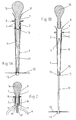
- the length of the portion 21 of the body may be limited to the radius of the discoidal element 12; in the case of a long-shoulder bottle as shown in Figures 3A, 3B and 4 , the tubular body 1 should extend approximately to the connection of the shoulder with the body of the bottle (about 15 cm from the rim of the neck).
- the length of the tubular body 1 could be substantially shortened, it is however the long body conformation which is adopted in practice as being suitable for all types of bottles, so as not to multiply the different models of the device.
- FIG. figure 3B the simplest way of introducing the device inside a container 4 is that which is illustrated in FIG. figure 3B : the guide rod 11 being erased inside the tubular body 1, the discoidal element 12, forced by the wall of the neck 3 of the container, is collected in an umbrella around the body 1 tubular.
- the portion 21 of the tubular body 1 which is underlying said upper mounting portion 2 has a substantially smaller diameter than that of said upper mounting portion 2.
- annular space is left free between the tubular body 1 and the wall of the neck 3 of the container during the introduction of the device through the neck 3 of a container 4, annular space which is adapted to receive the element 12 discoidal, picked up around the tubular body.
- portion 21 being cylindrical of revolution with a smaller diameter, forming a shoulder with the mounting portion 2
- portion 21 of the tubular body 1 underlying said upper mounting portion 2 is substantially conical frustoconical turned towards the lower end of the tubular body 1 as shown in FIGS. Figures 1A and 1B .
- the tubular body 1 is open in its lower part below the mounting portion 2.
- the tubular body 1 has a relatively large height for the reason explained above so that, being installed in a container as shown in FIG. figure 4 it extends quite deep inside of it. It is then desirable, so that it is possible to pour all the liquid out of the container even when there is relatively little left in the container, to provide at least one opening immediately below the upper portion 2 mounting.
- the guide rod 11 is supported by the tubular body 1 telescopically, so that it can be erased at least partly in the tubular body 1 when the device is not used as shown in FIG. Figure 1A .
- the tubular body 1 is closed at its lower end by a bottom 14 pierced with a passage 15 through which is engaged the guide rod 11.
- a boss 22 (better visible in the figure 4 ) located above the enlarged head 13 of the lower end of the guide rod 11.
- the boss 22 has a transverse dimension greater than that of the passage 15 of the bottom 14, but less than that of the central hole of the disc element 12.
- the boss 22 is thus able to bear against the bottom 14 and hold the rod in the erased position in the tubular body 1 as shown in FIG. Figure 1A ; the guide rod 11 can be disengaged by a thrust on its upper end, for example by means of the closure member 10 which, in the position shown in FIG. figure 3A is not fully embedded in the tubular body.
- the guide rod 11 is equipped, at its upper end which remains internal to the tubular body 1, an enlarged head retaining 16.
- the figure 2 presents a variant embodiment in which the tubular body 1 is significantly shorter than that shown in Figures 1A and 1B , and may for example be considered in combination with a discoidal element 12 of reduced diameter, for example to fit a smaller diameter container (eg half-bottle).
- a smaller diameter container eg half-bottle
- the container 4 with a rounded shoulder (type Bordeaux bottle) of lower height.
- the tubular body 1 can be made relatively short and extend only approximately to the height of the neck. The installation of the device then requires to collect the discoidal element 12 on itself downwards, opposite the tubular body 1, and to introduce it as well.
- the tubular body 1 may then have a lower axial opening 17 which can easily be used by the liquid when the container is inclined.
- Several legs 18, for example four or six regularly distributed angularly, which extend in the extension of the tubular body 1 support a plate 19 disposed coaxially facing the lower opening 17 and an axial distance therefrom. It is then the plate 19 which is provided with the passage 15 through which the guide rod 11 passes.
- the disk-shaped disc-shaped member 12 has a diameter approximately corresponding to the inside diameter of the body 20 of the container 4; the protection of the liquid will be all the better that the liquid surface in contact with the ambient atmosphere will be reduced, and therefore the diameter of the discoidal element 12 will be better adjusted to the inside diameter of the body 20 of the container.
- the discoidal element 12 may be made of any elastically deformable material which is inert with respect to the the liquid contained in the container 4. It is in the form of a flexible membrane which can be thicker and / or reinforced towards its center and thinned towards its periphery. The discoidal element 12 is thus able to deform appreciably, by closing in an umbrella around the rod 11 during the introduction of the device into the neck 3 of a container 4 as shown in FIG.
- figure 3B (The friction of the element 12 against the wall of the neck 3 that the rod 11 is then pushed into the tubular body 1), or by turning away from the rod 11 during the extraction of the device out of the neck 3 of the container 4 as shown in figure 3A (The friction of the element 12 against the wall of the neck 3 that the rod 11 is then pulled out of the tubular body 1).
- the figure 5 shows a bottle equipped with the device Figures 1A, 1B and inclined in pouring position of the liquid. It flows unhindered through the lights 9, while the discoidal element 12, because it is floating and free on the rod 11, can tilt and let the liquid flow.
- the path of the liquid has been schematized by an arrow F.
- the device according to the invention which has just been described may be equipped with a removable filter (not shown) suitable for retaining particles present in the liquid (deposit in a wine for example).
Landscapes
- Engineering & Computer Science (AREA)
- Food Science & Technology (AREA)
- Mechanical Engineering (AREA)
- Details Of Rigid Or Semi-Rigid Containers (AREA)
- Packages (AREA)
- Closures For Containers (AREA)
- Medical Preparation Storing Or Oral Administration Devices (AREA)
- Devices For Use In Laboratory Experiments (AREA)
Claims (10)
- Schutzvorrichtung zum Schutz einer Flüssigkeit, die sich in einem Behälter (4) mit Hals (3) befindet, gegen die sie umgebende Atmosphäre. Diese Schutzvorrichtung besteht aus einem scheibenförmigen Bauteil (12), das aus einem verformbaren elastischen Material besteht, dass eine geringere Dichte aufweist, als die Flüssigkeit und das gemäß dem Innendurchmesser des genannten Behälters (4) dimensioniert ist, sowie mit einer Halterung um das genannte scheibenförmige Bauteil (12) im Inneren des Behälters (4) zu halten,
Charakterisiert dadurch, dass die Halterung besteht aus:- einem röhrenförmigen Körper, der obere Montageteil (2) dient zum Einfügen mittels Reibung in den Hals (3) des genannten Behälters (4), dieser röhrenförmige Körper(1) ist mit einer axialen oberen Öffnung (8) ausgestattet und ist in seinem Teil (21) unter dem genannten oberen Montageteil (2) offen,- einem beweglichen abnehmbaren Stopfen, um die genannte obere axiale Öffnung (8) des röhrenförmigen Körpers (1) zu verschließen,- einem Führungsschaft (11), axial gehaltert durch das untere Ende des genannten röhrenförmigen Körpers (1)- das oben genannte scheibenförmige Bauteil (12) ist axial durchbohrt und frei gleitend auf dem genannten Führungsschaft (11) montiert,dank dessen kann das scheibenförmige Bauteil (12) auf der freien Oberfläche der Flüssigkeit ruhen und deren Niveauveränderungen innerhalb des Behälters (4) mitmachen und die Vorrichtung erlaubt das Ausschütten der Flüssigkeit aus dem schräg gehaltenen Behälter (4), wenn der Verschlussstopfen (10) abgenommen wurde. - Vorrichtung gemäß Anforderung 1, charakterisiert dadurch, dass der Teil (21) des röhrenförmigen Körpers (1), der sich direkt unter dem oberen axialen Montageteil (2) befindet, eine solche Länge aufweist, dass das scheibenförmige Bauteil (12), das um den röhrenförmigen Körper gefaltet ist, sich nach dem Einführen der Vorrichtung durch den Hals (3) des Behälters (4) frei im Körper des Behälters (20) entfalten kann, sobald die Vorrichtung innerhalb des Behälters an ihrem Platz angelangt ist.
- Vorrichtung gemäß den Anforderungen 1 und 2, charakterisiert dadurch, dass der Teil (21) des röhrenförmigen Körpers (1), der sich unterhalb des oberen Montageteils (2) befindet, einen Durchmesser besitzt, der etwas kleiner ist als der des genannten oberen Montageteils (2), dank dessen bleibt ein ringförmiger Platz frei zwischen dem röhrenförmigen Körper (1) und der Innenwand des Halses (3) des Behälters (4), ein ringförmiger Raum, der geeignet ist, das scheibenförmige Bauteil (12) aufzunehmen, dass um den röhrenförmigen Körper (1) herum gefaltet ist.
- Vorrichtung gemäß Anforderung 3, charakterisiert dadurch, dass der Teil (21) des röhrenförmigen Körpers (1), der sich direkt unter dem oberen Montageteil (2) befindet, leicht kegelförmig ist mit einer Neigung bzw. Abwinkelung in Richtung auf das untere Ende des röhrenförmigen Körpers (1).
- Vorrichtung gemäß einer der Anforderungen 1 bis 4, charakterisiert dadurch, dass das obere Montageteil (2) des röhrenförmigen Körpers (1) geeignet ist, an einer Wasserdichtigkeit mit dem Hals (3) des Behälters (4) mitzuwirken.
- Vorrichtung gemäß der Anforderung 5, charakterisiert dadurch, dass der röhrenförmige Körper (1) über mindestens eine periphere äußere Rippe verfügt, die radial übersteht.
- Vorrichtung gemäß einer der Anforderungen 1 bis 6, charakterisiert dadurch, dass der röhrenförmige Körper an seinem unteren Ende durch einen Boden (14) verschlossen ist und dass er über mindestens einen offenen transversalen Kanal an der Seitenwand des röhrenförmigen Körpers (1) verfügt.
- Vorrichtung gemäß Anforderung 7, charakterisiert dadurch, dass der röhrenförmige Körper (1) über mehrere transversale Kanäle (9) verfügt, die regelmäßig auf den Umfang verteilt sind.
- Vorrichtung gemäß einer der Anforderungen 1 bis 8, charakterisiert dadurch, dass der Führungsschaft (11) durch das Ende des röhrenförmigen Körpers (1) gleitend gehaltert wird, dank dessen kann der Führungsschaft eine nichtfunktionale Position einnehmen, bei der er zumindest teilweise wie teleskopisch in den röhrenförmigen Körper (1) eingeschoben wird.
- Vorrichtung gemäß der Anforderung 8, charakterisiert dadurch, dass der Boden (14) des röhrenförmigen Körpers (1) mit einem Durchlass (15) ausgestattet ist, und dass der Führungsschaft (11) dadurch in dem genannten Durchlass (15) eingehängt ist.
Applications Claiming Priority (2)
| Application Number | Priority Date | Filing Date | Title |
|---|---|---|---|
| FR0513408A FR2895376B1 (fr) | 2005-12-28 | 2005-12-28 | Dispositif de protection,vis a vis de l'atmosphere qui le surmonte, d'un liquide dans un recipient a col. |
| PCT/IB2006/003773 WO2007074382A2 (fr) | 2005-12-28 | 2006-12-27 | Dispositif de protection, vis-a-vis de l'atmosphere qui le surmonte, d'un liquide dans un recipient a col |
Publications (2)
| Publication Number | Publication Date |
|---|---|
| EP1973807A2 EP1973807A2 (de) | 2008-10-01 |
| EP1973807B1 true EP1973807B1 (de) | 2009-12-02 |
Family
ID=36974701
Family Applications (1)
| Application Number | Title | Priority Date | Filing Date |
|---|---|---|---|
| EP06842279A Not-in-force EP1973807B1 (de) | 2005-12-28 | 2006-12-27 | Vorrichtung zum schutz einer flüssigkeit vor der darüberliegenden atmosphäre in einem behälter mit hals |
Country Status (5)
| Country | Link |
|---|---|
| EP (1) | EP1973807B1 (de) |
| AT (1) | ATE450454T1 (de) |
| DE (1) | DE602006010908D1 (de) |
| FR (1) | FR2895376B1 (de) |
| WO (1) | WO2007074382A2 (de) |
Families Citing this family (1)
| Publication number | Priority date | Publication date | Assignee | Title |
|---|---|---|---|---|
| SE535072C2 (sv) * | 2010-08-30 | 2012-04-03 | Konsolvia Ab | Anordning och förfarande för bevarande av en produkt förvarad i en med en öppning försedd behållare |
Family Cites Families (4)
| Publication number | Priority date | Publication date | Assignee | Title |
|---|---|---|---|---|
| BE636572A (de) * | ||||
| GB2237844A (en) * | 1989-11-09 | 1991-05-15 | Enzo Casale | Drawing off liquids from containers |
| DE19858576A1 (de) * | 1998-12-18 | 2000-06-21 | Albert Haefner | Behälter zum Aufbewahren von flüssigen oder festen Stoffen unter Luftabschluß |
| US20030102311A1 (en) * | 2001-12-05 | 2003-06-05 | Brady James R. | Method and or apparatus to reduce the oxidation of liquids including wine, whiskey, oils, paint and others after the orginial sealed bottle or container has been opened for the first time or is placed into original bottlw, can or container when filled for the first time by the manufacture |
-
2005
- 2005-12-28 FR FR0513408A patent/FR2895376B1/fr not_active Expired - Fee Related
-
2006
- 2006-12-27 WO PCT/IB2006/003773 patent/WO2007074382A2/fr not_active Ceased
- 2006-12-27 EP EP06842279A patent/EP1973807B1/de not_active Not-in-force
- 2006-12-27 AT AT06842279T patent/ATE450454T1/de not_active IP Right Cessation
- 2006-12-27 DE DE602006010908T patent/DE602006010908D1/de not_active Expired - Fee Related
Also Published As
| Publication number | Publication date |
|---|---|
| DE602006010908D1 (de) | 2010-01-14 |
| ATE450454T1 (de) | 2009-12-15 |
| WO2007074382A2 (fr) | 2007-07-05 |
| FR2895376B1 (fr) | 2008-02-01 |
| EP1973807A2 (de) | 2008-10-01 |
| FR2895376A1 (fr) | 2007-06-29 |
| WO2007074382A3 (fr) | 2007-10-04 |
Similar Documents
| Publication | Publication Date | Title |
|---|---|---|
| EP2822873B1 (de) | Einsatz zur befestigung eines beutels in einer dose | |
| EP1044893A1 (de) | Vorrichtung zum unmittelbaren Vermischen von mindestens zwei Produkten, von denen eines ein Pulver ist | |
| EP0626321B1 (de) | Flüssigkeitsabgabevorrichtung ohne Saugrohr | |
| FR2502591A1 (fr) | Assemblage de liaison pour systemes a deux composantes | |
| EP3094418B1 (de) | Flüssigkeitsbehälter und spender | |
| FR3046142A1 (fr) | Conteneur de stockage et de decharge individuelle de capsules | |
| FR2895374A1 (fr) | Bague pour valve aerosol. | |
| EP2348812B1 (de) | Autonomer träger mit umkippschutz für blumensträusse | |
| EP1973807B1 (de) | Vorrichtung zum schutz einer flüssigkeit vor der darüberliegenden atmosphäre in einem behälter mit hals | |
| FR2924099A1 (fr) | Bouchon permettant la diffusion d'un produit fluide | |
| WO2011058272A1 (fr) | Contenant pour fluide comportant une poche destinee a contenir ledit fluide, et fut associe | |
| FR2718110A1 (fr) | Dispositif mécanique pour extraire un produit crémeux, pâteux ou liquide d'un récipient contenant le produit, et ensemble distributeur incorporant un tel dispositif. | |
| FR2677106A1 (fr) | Bouteille a gaz. | |
| WO2015091597A1 (fr) | Dispositif d'obturation d'un recipient presentant un col | |
| EP2366635B1 (de) | Deckelanordnung und Gehäuse, das eine solche Deckelanordnung umfasst | |
| WO2026093671A1 (fr) | Dispositif de remplissage d'un contenant tel qu'une capsule, notamment une capsule pour machine a cafe, et systeme de remplissage comportant un tel dispositif | |
| EP1114594B1 (de) | Spender, der dem Benutzer die Möglichkeit gibt, die Farbe des Produktes zu erkennen | |
| EP2146923B1 (de) | Verschlussdeckel für einen behälter zur aufbewahrung von kohlensäurehaltigen flüssigkeiten und behälter mit derartigem verschluss | |
| FR2807012A1 (fr) | Bouchon-verseur pour bouteille ou recipient analogue | |
| WO2014199060A1 (fr) | Dispositif anti-goutte décoratif | |
| EP4304949A1 (de) | Öffnungsvorrichtung mit integriertem strohhalm und verfahren zur herstellung der vorrichtung | |
| WO2009056770A1 (fr) | Dispositif doseur adaptable sur un contenant | |
| CA1050487A (fr) | Capsule pour la confection de produits a distribuer sous l'effet d'un fluide sous pression | |
| BE892624A (fr) | Assemblage de liaison pour systemes a deux composantes | |
| FR2950331A1 (fr) | Distributeur de boisson. |
Legal Events
| Date | Code | Title | Description |
|---|---|---|---|
| PUAI | Public reference made under article 153(3) epc to a published international application that has entered the european phase |
Free format text: ORIGINAL CODE: 0009012 |
|
| 17P | Request for examination filed |
Effective date: 20080513 |
|
| AK | Designated contracting states |
Kind code of ref document: A2 Designated state(s): AT BE BG CH CY CZ DE DK EE ES FI FR GB GR HU IE IS IT LI LT LU LV MC NL PL PT RO SE SI SK TR |
|
| GRAP | Despatch of communication of intention to grant a patent |
Free format text: ORIGINAL CODE: EPIDOSNIGR1 |
|
| GRAS | Grant fee paid |
Free format text: ORIGINAL CODE: EPIDOSNIGR3 |
|
| DAX | Request for extension of the european patent (deleted) | ||
| GRAA | (expected) grant |
Free format text: ORIGINAL CODE: 0009210 |
|
| AK | Designated contracting states |
Kind code of ref document: B1 Designated state(s): AT BE BG CH CY CZ DE DK EE ES FI FR GB GR HU IE IS IT LI LT LU LV MC NL PL PT RO SE SI SK TR |
|
| REG | Reference to a national code |
Ref country code: GB Ref legal event code: FG4D Free format text: NOT ENGLISH |
|
| REG | Reference to a national code |
Ref country code: CH Ref legal event code: EP |
|
| REG | Reference to a national code |
Ref country code: IE Ref legal event code: FG4D |
|
| REF | Corresponds to: |
Ref document number: 602006010908 Country of ref document: DE Date of ref document: 20100114 Kind code of ref document: P |
|
| REG | Reference to a national code |
Ref country code: NL Ref legal event code: VDEP Effective date: 20091202 |
|
| PG25 | Lapsed in a contracting state [announced via postgrant information from national office to epo] |
Ref country code: SE Free format text: LAPSE BECAUSE OF FAILURE TO SUBMIT A TRANSLATION OF THE DESCRIPTION OR TO PAY THE FEE WITHIN THE PRESCRIBED TIME-LIMIT Effective date: 20091202 Ref country code: LT Free format text: LAPSE BECAUSE OF FAILURE TO SUBMIT A TRANSLATION OF THE DESCRIPTION OR TO PAY THE FEE WITHIN THE PRESCRIBED TIME-LIMIT Effective date: 20091202 Ref country code: FI Free format text: LAPSE BECAUSE OF FAILURE TO SUBMIT A TRANSLATION OF THE DESCRIPTION OR TO PAY THE FEE WITHIN THE PRESCRIBED TIME-LIMIT Effective date: 20091202 |
|
| LTIE | Lt: invalidation of european patent or patent extension |
Effective date: 20091202 |
|
| PG25 | Lapsed in a contracting state [announced via postgrant information from national office to epo] |
Ref country code: LV Free format text: LAPSE BECAUSE OF FAILURE TO SUBMIT A TRANSLATION OF THE DESCRIPTION OR TO PAY THE FEE WITHIN THE PRESCRIBED TIME-LIMIT Effective date: 20091202 Ref country code: CY Free format text: LAPSE BECAUSE OF FAILURE TO SUBMIT A TRANSLATION OF THE DESCRIPTION OR TO PAY THE FEE WITHIN THE PRESCRIBED TIME-LIMIT Effective date: 20091202 Ref country code: PL Free format text: LAPSE BECAUSE OF FAILURE TO SUBMIT A TRANSLATION OF THE DESCRIPTION OR TO PAY THE FEE WITHIN THE PRESCRIBED TIME-LIMIT Effective date: 20091202 Ref country code: SI Free format text: LAPSE BECAUSE OF FAILURE TO SUBMIT A TRANSLATION OF THE DESCRIPTION OR TO PAY THE FEE WITHIN THE PRESCRIBED TIME-LIMIT Effective date: 20091202 |
|
| BERE | Be: lapsed |
Owner name: LABBE', JEAN CLAUDE Effective date: 20091231 |
|
| PG25 | Lapsed in a contracting state [announced via postgrant information from national office to epo] |
Ref country code: AT Free format text: LAPSE BECAUSE OF FAILURE TO SUBMIT A TRANSLATION OF THE DESCRIPTION OR TO PAY THE FEE WITHIN THE PRESCRIBED TIME-LIMIT Effective date: 20091202 |
|
| REG | Reference to a national code |
Ref country code: IE Ref legal event code: FD4D |
|
| PG25 | Lapsed in a contracting state [announced via postgrant information from national office to epo] |
Ref country code: MC Free format text: LAPSE BECAUSE OF NON-PAYMENT OF DUE FEES Effective date: 20100701 Ref country code: ES Free format text: LAPSE BECAUSE OF FAILURE TO SUBMIT A TRANSLATION OF THE DESCRIPTION OR TO PAY THE FEE WITHIN THE PRESCRIBED TIME-LIMIT Effective date: 20100313 Ref country code: IS Free format text: LAPSE BECAUSE OF FAILURE TO SUBMIT A TRANSLATION OF THE DESCRIPTION OR TO PAY THE FEE WITHIN THE PRESCRIBED TIME-LIMIT Effective date: 20100402 Ref country code: PT Free format text: LAPSE BECAUSE OF FAILURE TO SUBMIT A TRANSLATION OF THE DESCRIPTION OR TO PAY THE FEE WITHIN THE PRESCRIBED TIME-LIMIT Effective date: 20100402 Ref country code: IE Free format text: LAPSE BECAUSE OF FAILURE TO SUBMIT A TRANSLATION OF THE DESCRIPTION OR TO PAY THE FEE WITHIN THE PRESCRIBED TIME-LIMIT Effective date: 20091202 Ref country code: EE Free format text: LAPSE BECAUSE OF FAILURE TO SUBMIT A TRANSLATION OF THE DESCRIPTION OR TO PAY THE FEE WITHIN THE PRESCRIBED TIME-LIMIT Effective date: 20091202 Ref country code: BG Free format text: LAPSE BECAUSE OF FAILURE TO SUBMIT A TRANSLATION OF THE DESCRIPTION OR TO PAY THE FEE WITHIN THE PRESCRIBED TIME-LIMIT Effective date: 20100302 Ref country code: NL Free format text: LAPSE BECAUSE OF FAILURE TO SUBMIT A TRANSLATION OF THE DESCRIPTION OR TO PAY THE FEE WITHIN THE PRESCRIBED TIME-LIMIT Effective date: 20091202 Ref country code: RO Free format text: LAPSE BECAUSE OF FAILURE TO SUBMIT A TRANSLATION OF THE DESCRIPTION OR TO PAY THE FEE WITHIN THE PRESCRIBED TIME-LIMIT Effective date: 20091202 |
|
| PG25 | Lapsed in a contracting state [announced via postgrant information from national office to epo] |
Ref country code: SK Free format text: LAPSE BECAUSE OF FAILURE TO SUBMIT A TRANSLATION OF THE DESCRIPTION OR TO PAY THE FEE WITHIN THE PRESCRIBED TIME-LIMIT Effective date: 20091202 Ref country code: CZ Free format text: LAPSE BECAUSE OF FAILURE TO SUBMIT A TRANSLATION OF THE DESCRIPTION OR TO PAY THE FEE WITHIN THE PRESCRIBED TIME-LIMIT Effective date: 20091202 |
|
| PLBE | No opposition filed within time limit |
Free format text: ORIGINAL CODE: 0009261 |
|
| STAA | Information on the status of an ep patent application or granted ep patent |
Free format text: STATUS: NO OPPOSITION FILED WITHIN TIME LIMIT |
|
| PG25 | Lapsed in a contracting state [announced via postgrant information from national office to epo] |
Ref country code: BE Free format text: LAPSE BECAUSE OF NON-PAYMENT OF DUE FEES Effective date: 20091231 Ref country code: GR Free format text: LAPSE BECAUSE OF FAILURE TO SUBMIT A TRANSLATION OF THE DESCRIPTION OR TO PAY THE FEE WITHIN THE PRESCRIBED TIME-LIMIT Effective date: 20100303 |
|
| 26N | No opposition filed |
Effective date: 20100903 |
|
| PG25 | Lapsed in a contracting state [announced via postgrant information from national office to epo] |
Ref country code: DE Free format text: LAPSE BECAUSE OF NON-PAYMENT OF DUE FEES Effective date: 20100701 |
|
| PG25 | Lapsed in a contracting state [announced via postgrant information from national office to epo] |
Ref country code: DK Free format text: LAPSE BECAUSE OF FAILURE TO SUBMIT A TRANSLATION OF THE DESCRIPTION OR TO PAY THE FEE WITHIN THE PRESCRIBED TIME-LIMIT Effective date: 20091202 |
|
| PG25 | Lapsed in a contracting state [announced via postgrant information from national office to epo] |
Ref country code: IT Free format text: LAPSE BECAUSE OF FAILURE TO SUBMIT A TRANSLATION OF THE DESCRIPTION OR TO PAY THE FEE WITHIN THE PRESCRIBED TIME-LIMIT Effective date: 20091202 |
|
| REG | Reference to a national code |
Ref country code: FR Ref legal event code: ST Effective date: 20110228 |
|
| PG25 | Lapsed in a contracting state [announced via postgrant information from national office to epo] |
Ref country code: LU Free format text: LAPSE BECAUSE OF NON-PAYMENT OF DUE FEES Effective date: 20091227 |
|
| PG25 | Lapsed in a contracting state [announced via postgrant information from national office to epo] |
Ref country code: FR Free format text: LAPSE BECAUSE OF NON-PAYMENT OF DUE FEES Effective date: 20100202 |
|
| PG25 | Lapsed in a contracting state [announced via postgrant information from national office to epo] |
Ref country code: HU Free format text: LAPSE BECAUSE OF FAILURE TO SUBMIT A TRANSLATION OF THE DESCRIPTION OR TO PAY THE FEE WITHIN THE PRESCRIBED TIME-LIMIT Effective date: 20100603 |
|
| REG | Reference to a national code |
Ref country code: CH Ref legal event code: PL |
|
| GBPC | Gb: european patent ceased through non-payment of renewal fee |
Effective date: 20101227 |
|
| PG25 | Lapsed in a contracting state [announced via postgrant information from national office to epo] |
Ref country code: TR Free format text: LAPSE BECAUSE OF FAILURE TO SUBMIT A TRANSLATION OF THE DESCRIPTION OR TO PAY THE FEE WITHIN THE PRESCRIBED TIME-LIMIT Effective date: 20091202 |
|
| PG25 | Lapsed in a contracting state [announced via postgrant information from national office to epo] |
Ref country code: CH Free format text: LAPSE BECAUSE OF NON-PAYMENT OF DUE FEES Effective date: 20101231 Ref country code: LI Free format text: LAPSE BECAUSE OF NON-PAYMENT OF DUE FEES Effective date: 20101231 |
|
| PG25 | Lapsed in a contracting state [announced via postgrant information from national office to epo] |
Ref country code: GB Free format text: LAPSE BECAUSE OF NON-PAYMENT OF DUE FEES Effective date: 20101227 |