EP1974103B1 - Gehäuse zum schützen und verdecken eines toilettenbeckens und damit versehenes toilettenbecken - Google Patents
Gehäuse zum schützen und verdecken eines toilettenbeckens und damit versehenes toilettenbecken Download PDFInfo
- Publication number
- EP1974103B1 EP1974103B1 EP07712629A EP07712629A EP1974103B1 EP 1974103 B1 EP1974103 B1 EP 1974103B1 EP 07712629 A EP07712629 A EP 07712629A EP 07712629 A EP07712629 A EP 07712629A EP 1974103 B1 EP1974103 B1 EP 1974103B1
- Authority
- EP
- European Patent Office
- Prior art keywords
- bowl
- housing
- toilet bowl
- toilet
- intended
- Prior art date
- Legal status (The legal status is an assumption and is not a legal conclusion. Google has not performed a legal analysis and makes no representation as to the accuracy of the status listed.)
- Not-in-force
Links
- 230000000873 masking effect Effects 0.000 title claims description 5
- XLYOFNOQVPJJNP-UHFFFAOYSA-N water Substances O XLYOFNOQVPJJNP-UHFFFAOYSA-N 0.000 claims abstract description 24
- 230000000295 complement effect Effects 0.000 claims abstract description 12
- 238000004873 anchoring Methods 0.000 claims abstract description 11
- 230000002093 peripheral effect Effects 0.000 claims abstract description 9
- 238000005192 partition Methods 0.000 claims description 12
- 238000009826 distribution Methods 0.000 claims description 8
- 230000002441 reversible effect Effects 0.000 claims description 2
- 239000000463 material Substances 0.000 abstract description 12
- 239000004033 plastic Substances 0.000 abstract description 3
- 229920003023 plastic Polymers 0.000 abstract description 3
- 239000002131 composite material Substances 0.000 abstract description 2
- 229910001220 stainless steel Inorganic materials 0.000 abstract description 2
- 239000010935 stainless steel Substances 0.000 abstract description 2
- 239000002023 wood Substances 0.000 abstract description 2
- 239000000919 ceramic Substances 0.000 description 6
- 238000012423 maintenance Methods 0.000 description 6
- 230000036961 partial effect Effects 0.000 description 6
- 238000009434 installation Methods 0.000 description 5
- 238000004140 cleaning Methods 0.000 description 4
- 208000031968 Cadaver Diseases 0.000 description 3
- 238000004519 manufacturing process Methods 0.000 description 3
- 241001080024 Telles Species 0.000 description 2
- 244000245420 ail Species 0.000 description 2
- 230000000694 effects Effects 0.000 description 2
- 230000000670 limiting effect Effects 0.000 description 2
- 230000001681 protective effect Effects 0.000 description 2
- 239000011347 resin Substances 0.000 description 2
- 229920005989 resin Polymers 0.000 description 2
- 238000007789 sealing Methods 0.000 description 2
- 239000007787 solid Substances 0.000 description 2
- 208000006558 Dental Calculus Diseases 0.000 description 1
- 230000001154 acute effect Effects 0.000 description 1
- 239000011324 bead Substances 0.000 description 1
- 238000006243 chemical reaction Methods 0.000 description 1
- 238000010276 construction Methods 0.000 description 1
- 238000010586 diagram Methods 0.000 description 1
- 238000006073 displacement reaction Methods 0.000 description 1
- 229940082150 encore Drugs 0.000 description 1
- 230000002349 favourable effect Effects 0.000 description 1
- 238000011010 flushing procedure Methods 0.000 description 1
- 239000006260 foam Substances 0.000 description 1
- 239000007943 implant Substances 0.000 description 1
- 238000002513 implantation Methods 0.000 description 1
- 230000010354 integration Effects 0.000 description 1
- 239000002184 metal Substances 0.000 description 1
- 239000002304 perfume Substances 0.000 description 1
- 239000011505 plaster Substances 0.000 description 1
- 238000011084 recovery Methods 0.000 description 1
- 230000002829 reductive effect Effects 0.000 description 1
- 230000000284 resting effect Effects 0.000 description 1
- 239000010865 sewage Substances 0.000 description 1
- 239000002904 solvent Substances 0.000 description 1
- 238000003860 storage Methods 0.000 description 1
Images



Classifications
-
- E—FIXED CONSTRUCTIONS
- E03—WATER SUPPLY; SEWERAGE
- E03D—WATER-CLOSETS OR URINALS WITH FLUSHING DEVICES; FLUSHING VALVES THEREFOR
- E03D11/00—Other component parts of water-closets, e.g. noise-reducing means in the flushing system, flushing pipes mounted in the bowl, seals for the bowl outlet, devices preventing overflow of the bowl contents; devices forming a water seal in the bowl after flushing, devices eliminating obstructions in the bowl outlet or preventing backflow of water and excrements from the waterpipe
- E03D11/02—Water-closet bowls ; Bowls with a double odour seal optionally with provisions for a good siphonic action; siphons as part of the bowl
Definitions
- the present invention relates to a guard for protecting and masking a toilet bowl.
- Toilet bowls are traditionally made of ceramic.
- Ceramic is, during the manufacturing process, a dimensionally unstable material. Thus, the dimensions of the products manufactured are difficult to control and not constant from one room to another. This has not favored the manufacture of cuvettes in several subassemblies to assemble, as well as the variety of products in terms of shape.
- a cover or housing which is intended to hide the toilet bowl, including covering the upper portion of the bowl of the bowl which is shaped in peripheral flange folded inwards.
- This hood consists of a single piece, so that its introduction and removal requires some dexterity.
- the document US 331,993 discloses a toilet assembly which includes a bowl bowl having in its upper open portion a drip tray which is secured under the top of a body surrounding the bowl and a toilet seat being positioned above it tray in extension of said body and which it is fixed by a hinge.
- a toilet assembly comprising a housing comprising a main body in which is disposed the bowl of the toilet and a cover piece permanently assembled to the main body or in the form of a monobloc.
- the document DE 93 09 173U discloses an assembly with a toilet bowl comprising a housing formed of a main body in which is disposed the bowl of the bowl and a cover piece, the workpiece and the body being assembled.
- the document US4,145,772 discloses an assembly with a toilet bowl, comprising a casing formed of a main body which is an outer shell in which is disposed the bowl of the bowl and a cover piece which is an outer plastic shell open in the center and disposed above a part comprising a water reservoir open at its center and disposed above the bowl, these two shells being fixed to each other permanently by a foam or a fixing solvent.
- US 3,908,202 discloses a toilet assembly comprising a housing disposed on the front of the bowl of the bowl and attached to a cover piece by screws.
- the present invention aims to solve these disadvantages by proposing an easy to install and remove housing, which facilitates any particular technical intervention behind the bowl, but which is quite stable during normal use of the toilet in association with a removable cover piece.
- the upper portion of the bowl is shaped inward flanged peripheral rim, which defines with this bowl a distribution channel of water "R".
- This casing is characterized by the characterizing part of claim 1.
- the body and the cover piece forming two separate parts, it is particularly easy to put in place and remove them, which allows the handling of the housing without requiring special dexterity.
- Another advantage of this structure is that it is scalable, that is to say that some elements that constitute it can be replaced by others, without this affecting the operation of the whole.
- the design potential of this bowl due to the possibility of using various stable materials (plastics, composites, stainless steel, wood, ...) becomes significant.
- the present invention also relates to a bowl provided with a housing according to one of the features listed above.
- the inwardly folded peripheral flange which delimits with the bowl a water distribution channel constitutes a separate part of said bowl.
- said rim and said bowl each have at least one notch intended to come opposite each other, as well as a water supply conduit engaged in the pair of notches.
- the casing of the bowl is supported on an anchor base and cooperates with said base by a pivot type connection.
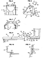
- the toilet bowl that is represented at the figure 1 is typical of those which can receive the masking and protection casing according to the invention. It can be manufactured in any suitable material, known to those skilled in the art, such as "resin concrete”.
- This bowl 1 comprises, in the usual manner, a bowl 10 whose upper part is shaped in peripheral flange folded inwards.
- a conduit 100 for draining sewage forming siphon At the bottom of the bowl is connected a conduit 100 for draining sewage forming siphon.
- this duct opens a tubular 101 whose upper end extends behind the bowl 1, slightly higher than its upper rim.
- This tubing is for example intended to receive a removable rod whose end is provided with a tartar collecting material.
- the top of this rod can be advantageously shaped plug closure of the tubing.
- At least one flexible pipe 21 supplies the bowl 10 of the bowl 1 with water.
- the flange 11 has a traditional U-shaped structure reversed, with a flat base 110 forming upper bearing surface and two substantially parallel flanges 111 and 112.
- the flange 112 extends in the extension of the wall of the bowl 10, while the flange 111 is an inner wall overlooking the inside of the bowl.
- the end 113 of the flange 112 and the upper periphery 102 of the bowl are shaped such that by a top-down engagement, the flange 11 is supported on the bowl 10 and remains in place. These ends and around here represent shoulders with complementary engagement.
- the extension 110 'of the outward rim allows the recovery of the crown 12 of the bowl 10 and the upper edge 302 of the housing 3 thus sealing the couple bowl / housing, especially when the cover piece is removed for cleaning. This is an example. Any other mode of cooperation is of course conceivable.
- the flange 11 delimits with the bowl 10 a water distribution channel R inside the bowl 1.
- the rim 11 has in its rear part two notches with a semicircle contour 114. The same is true for the corresponding region of the wall of the bowl 10. These notches are referenced 120 and have exactly the same shape as the previous ones, except that they open up.
- the ends 210 of the pipes are shaped to be able to engage in the notches and slightly overflow inside the bowl 10.
- lips are provided to ensure perfect water tightness.
- the water pipe is unique.
- the protective casing according to the invention is partly visible at the figure 5 . It is shown in place around a bowl 1 of which only the bowl 10 has been shown for the sake of simplification.
- the body 30 of this housing 3 represents approximately, seen from above, the shape of a "U” with a curved base 300 bearing against the front portion of the bowl 1, and two wings 301 and 302.
- This body may have a particular shape, especially to give the chosen aesthetic to the whole.
- the wings 301 and 302 do not necessarily have a strictly vertical orientation when the body 30 is in place.
- the two wings 301 and 302 are connected by a connecting element 31 which protrudes behind and above the upper plane P of the body 30.
- each wing 301, 302 has, bordering its free end, a vertical extension 310 which is folded at right angles inwards to form a plane support 311.
- the connecting element is provided with a plate vertically arranged bottom plate 312, which connects to each of the extensions 310 and the flat supports 311. It will be observed that this rear assembly constitutes a volume 307 serving as a free-sized housing in which the person skilled in the art can provide the installation of various equipment (tap ).
- the bottom plate 312 constitutes a surface adapted to come into contact with a not shown wall for securing with it.
- oblong holes 313 are formed and are particularly suitable for the implementation of screws.
- crankcase partially represented in the figure 7 has substantially the same structure as that already described, except that the wings 301 and 302 are separated from the vertical extensions 310 by a horizontal surface 303. This gives the junction element a reduced width.
- FIG. 6 To the figure 6 is shown a housing according to the invention, equipping a bowl resting on a tripod 4.
- a cover piece 32 which has an opening O at its center. It is intended to cover the peripheral rim 11 of the bowl.
- the piece 32 has an inverted “U” -shaped cross-section, with a flat base 320 forming an upper bearing surface and two substantially parallel wings 321 and 322.
- the wing " 322 may be provided longer than the "outer” flange 321 so as to "fit" partially into the bowl 10 of the bowl, beyond the lowest point of the rim 11.
- the mode of cooperation between the body 30 and the cover piece may be of the same kind as that with which the bowl 10 and the rim 11 are dealt with.
- figure 20 when the bowl is made of unstable material the rim 11 is inverted “L” -shaped and covers the edge 302 of the housing 30.
- the cover piece 32 has wings 322 and 323 forming an inverted “U” which delimits a water distribution channel "R".
- the wing 321 ensures a complementary holding in place of the cover piece and the lateral sealing of the casing 30.
- figure 21 when the bowl is made of a material allowing uniformity of the dimensions of the bowl the rim 12 is made in the bowl itself.
- the flange 12 in the shape of an inverted "L" facing outwards covers the rim 302 of the housing.
- the water pipe is directly connected to the cover piece which is then provided with at least one notch or hole.
- the end 210 of the tube, figure 4 is anchored to the bowl or wing of the cover piece.
- This support 4 ' has a rectangular base 40' intended to rest on the ground. Cutouts 400 'open on one of the big sides. They allow the passage of screws fixing the plate to the ground.
- the base of the plates 41 ' carries, on the external side, a small horizontal tab 410'.
- This lug is a guide and a stop for the installation of the body 30 of the housing, the lower rim thereof being shaped to be placed under the tab, thus preventing any movement of removal of the body of the housing in a direction vertical.
- the piece 43 ' is a plate that associated with the support 4 can carry equipment (vacuum cleaner, ).
- the casing 30 is supported on an anchor base 7 consisting of a wall of generally semicircular shape seen from above and trapezoidal seen from the side.
- This base 7, figure 24 is fixed to the ground by tabs 71, 71 ', 72.
- the casing that bears on the perimeter of the base has a continuous lip or not that penetrates into the base and which is in contact with the wall vertical of said base.
- the housing has a cross member 35, located at its base, connecting the two wings 301, 302.
- the general shape in a semicircle of the base, figure 24 is only an example of form.
- connection between the base and the housing makes it possible to implant a basin suspended along a plaster drywall.
- connection of the casing to the base at the point of support "A” makes it possible to pass on the drywall "C” via the crossbar 35, the load of a seated user on the bowl; the weight of the user causes a vertical rotation of the bowl, whose axis is said point "A", rotation oriented upwards.
- the pulling force of the partition of the part 312, figure 5 becomes virtually zero, if not zero because of the bearing surface of the crossbar 35 on said partition "C".
- the crossbar 35 is provided with holes for fixing on the partition M.
- the pulling force is essentially in the vertical plane, favorable solution especially for drywall.
- This anchor base solution has the merit of allowing easy installation of the bowl. If the bowl 10 is made of a dimensionally stable material, its flange 12 is supported on the perimeter of said bowl. If it is ceramic, the bowl is supported inside the housing on a continuous or discontinuous stop 306, figure 3 .
- a bearing 331 in the form of a gutter, which is intended to receive at least one journal of complementary shape integral with a movable element such as a flap forming a lid, a toilet seat, or a retractable urinal .
- a movable element such as a flap forming a lid, a toilet seat, or a retractable urinal .
- a housing 330 Still behind this pin is a housing 330 curved profile, the transverse opening is oriented rearward and slightly downward.
- This housing is a means of connection with an anchor 5 which will be described below.
- This anchoring piece is intended to cooperate with the body 30 of the housing.
- this piece constitutes the base of a water reservoir 54 intended to feed the bowl 1.
- the housing For attachment to the body 30 of the housing, it comprises in its lower part two vertical partitions 52 whose inner face has a rib 53 for its engagement in the body 30.
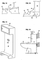
- the figure 11 shows the mode of cooperation between the anchor and the housing 30; and more precisely with the connecting element 31 thereof, in which the rib 53 of the part 5 engages in a rib complementary to the element 31.
- the figure 10 shows an alternative embodiment of these cooperation means, in which it is dispensed with rib and groove.
- the base of the part 5 is provided in its front portion with a transverse solid piece 51, the shape of which is strictly complementary, close to the game, that of the housing 330.
- the cover piece is provided with a pivot-type stud 34 which is inserted into a notch 511 configured in the ball 51.
- the cover piece vertically rotates in the axis of the stud, which allows to lift the cover piece without separating it from the piece 5.
- each of the wings 512 is equipped with the same device for housing in support of the pads of the cover piece.
- the housing 330 bears on the perimeter 510 of the ball 51; this wrapping has the effect of preventing any vertical and forward movement of the cover piece 32 when using the bowl.
- the wings 321 and / or 323 and / or 322 prevent any displacement of the cover piece in the horizontal plane.
- the cover piece allows the maintenance in place from front to back of the part 5 if it is not fixed by any other means to the housing or the wall. This solution allows easy maintenance of the bowl, the different subassemblies being removable.
- the part 5 comprises an orifice 513 for the passage of a tubing 101 associated with the bowl.
- the cover part may include, in suitable places, magnets cooperating with similar magnets housed in the upper part of the housing body. To remove the piece of cover, it is then necessary to overcome the resistance force exerted by the magnets, which may be likely to deter some malicious people.
- the connecting means (51, 330) of complementary shape have a ball-shaped contact surface of the ball-and-socket type.
- the housing 330 and massive part 51 are also curved profile, however, their orientation is strictly horizontal, so that their mutual engagement / release also operates in a horizontal direction.
- the anchoring piece 5 constitutes the base of a cupboard 55 whose door 56, in the closed position, is profiled to partially close the bearing 331 which has been discussed with reference to the figure 9 .
- connection means 330 and 51 consist respectively of a solid piece and a housing, both of horizontal orientation.
- the anchoring piece 5 constitutes the base of a column 57 of small thickness, whose upper part is shaped as a storage compartment 58.
- the column can incorporate means 570 for detecting the presence or absence of a person on the toilet, especially to automatically actuate the triggering of a flush.
- the compartment can serve as a reserve for cleaning products.
- the reservoirs that contain them are connected to flexible tubes housed in the column, the lower end of the distribution opens into the bowl 1.
- the housing 3 inserted into a partition C is fixed both to the ground S and to a wall M, so that the reservoir 54 (not shown in the figure) is embedded in the space between them.
- FIG 16 To the figure 16 is schematically represented a toilet bowl 1, said suspended bowl. In a manner known per se, it is a bowl without a support base on the ground.
- the casing which is represented Figures 17 and 18 allows to protect and hide this bowl with the wings 305, giving the illusion that it has a base of support on the ground.
- this housing 3 comprises a curved body whose shape is adapted to match that of the bowl, the lower portion having a central zone 304 substantially vertical and bulged, intended in particular to mask the pipe system associated with the bowl. It is precisely this central zone 304 that gives the illusion that the bowl rests on the ground S.
- This frame is preferably fixed to the wall M and / or the floor by any appropriate means.
- This frame serves as a mounting bracket to the toilet bowl (not visible in the figure), but also to the body 30 of the housing 3.
- the housing is partially engaged in the space between the wall M and the partition C.
- the partition has an opening of suitable dimensions.
- the fixing of the bowl and body 30 of the housing is done by any appropriate means such as screws, slides, etc.
- Technical solutions will preferably be used for easy dismantling of the elements.
- the frame 6 may constitute a support means for a not shown water distribution tank, which is sufficient to connect, for example by means of flexible pipes, on the one hand to the supply network and on the other hand, at the bowl.
- the casing according to the invention and more particularly its cover piece may be provided with additional equipment including for improving the comfort of the user.
- the cover piece 32 when associated with a flap, can receive automatic flushing means, including electronic type.
- the surface upper part 32 includes surfaces adapted to receive integral support elements of the armrests, when they are in the folded and horizontal position.
- the structure of the housing according to the invention can protect and hide a toilet bowl, whatever the configuration.
Landscapes
- Health & Medical Sciences (AREA)
- Life Sciences & Earth Sciences (AREA)
- Engineering & Computer Science (AREA)
- Hydrology & Water Resources (AREA)
- Public Health (AREA)
- Water Supply & Treatment (AREA)
- Sanitary Device For Flush Toilet (AREA)
- Toilet Supplies (AREA)
- Bidet-Like Cleaning Device And Other Flush Toilet Accessories (AREA)
Claims (9)
- Gehäuse zum Schützen und Verdecken eines Toilettenbeckens (1), bei dem der obere Teil der Schüssel (10) als nach innen umgebogener, umlaufender Rand ausgebildet ist, der mit dieser Schüssel einen Kanal (R) zur Wasserverteilung begrenzt,- wobei das Gehäuse aus einem Körper (30) und einem in seiner Mitte offenen und von dem Körper (30) unabhängigen Deckelteil (32) besteht, das auf diesem Körper positioniert werden und dabei den umlaufenden Rand (11) des Beckens überdecken soll;- und wobei der Körper (30) mit einem Verankerungsteil (5) versehen ist, das in einer umkehrbaren Weise mit dem Deckelteil (32) zusammenwirken soll, dadurch gekennzeichnet, dass diese Verankerungs- und Deckelteile (32) Verbindungsmittel (51, 330) von zueinander komplementärer Form aufweisen, die eine gekrümmte Berührungsfläche nach Art eines Kugelgelenks aufweisen.
- Gehäuse nach Anspruch 1, das von oben gesehen ungefähr die Form eines "U" annimmt, so dass dessen beide Schenkel (301) auf beiden Seiten des Beckens (1) verlaufen, dadurch gekennzeichnet, dass die Enden dieser Schenkel durch ein Verbindungselement (31) verbunden sind, das gegebenenfalls über die obere Ebene (P) des Körpers (30) hinausragt, wobei dieses Verbindungselement (31) insbesondere einen Träger für das Verankerungsteil (5) bildet.
- Gehäuse nach Anspruch 2, dadurch gekennzeichnet, dass das Verbindungselement (31) eine Fläche (312) aufweist, die so gestaltet ist, dass sie mit einer Trennwand in Berührung kommen kann, damit es mit dieser verbunden werden kann.
- Gehäuse nach einem der Ansprüche 1 bis 3, dadurch gekennzeichnet, dass das Verankerungsteil (5) die Grundfläche eines Wasserbehälters (54), der das Becken (1) versorgt, und/oder eines Einbauschranks (55) bildet.
- Gehäuse nach einem der Ansprüche 1 bis 4, dadurch gekennzeichnet, dass sich das Gehäuse (30) auf ein trapezförmiges Verankerungsunterteil (7) stützt.
- Gehäuse nach einem der vorhergehenden Ansprüche, dadurch gekennzeichnet, dass das Deckelteil (32) mindestens ein rinnenförmiges Lager (331) aufweist, dazu bestimmt, mindestens einen Lagerzapfen aufzunehmen, der aus einem Stück mit einem beweglichen Element wie einem eine Klappe bildenden Deckel, einer Brille oder einem Urinal besteht.
- Anordnung, die aus einem Gehäuse nach einem der Ansprüche 1 bis 6 und einem Toilettenbecken besteht, bei dem der obere Teil der Schlüssel (10) als nach innen umgebogener, umlaufender Rand ausgebildet ist, der mit dem Gehäuse zusammenwirkt.
- Einheit nach Anspruch 7, dadurch gekennzeichnet, dass der Rand (11) ein vom Becken (10) verschiedenes Teil bildet,
- Einheit nach Anspruch 8, dadurch gekennzeichnet, dass der Rand (11) und die Schüssel (10) jeweils mindestens eine Aussparung (114, 120) aufweisen, die einander gegenüberliegend angeordnet werden sollen, sowie eine Wasserversorgungsleitung (210), die in das Paar der Aussparungen eingepasst wird.
Applications Claiming Priority (2)
| Application Number | Priority Date | Filing Date | Title |
|---|---|---|---|
| FR0600022A FR2895756B1 (fr) | 2006-01-02 | 2006-01-02 | Carter de protection et de masquage d'une cuvette de toilettes et cuvette ainsi equipee |
| PCT/FR2007/000002 WO2007077390A2 (fr) | 2006-01-02 | 2007-01-02 | Carter de protection et de masquage d'une cuvette de toilettes et cuvette ainsi équipée |
Publications (2)
| Publication Number | Publication Date |
|---|---|
| EP1974103A2 EP1974103A2 (de) | 2008-10-01 |
| EP1974103B1 true EP1974103B1 (de) | 2012-04-11 |
Family
ID=36822321
Family Applications (1)
| Application Number | Title | Priority Date | Filing Date |
|---|---|---|---|
| EP07712629A Not-in-force EP1974103B1 (de) | 2006-01-02 | 2007-01-02 | Gehäuse zum schützen und verdecken eines toilettenbeckens und damit versehenes toilettenbecken |
Country Status (12)
| Country | Link |
|---|---|
| US (1) | US8191182B2 (de) |
| EP (1) | EP1974103B1 (de) |
| JP (1) | JP4897827B2 (de) |
| CN (1) | CN101365847B (de) |
| AT (1) | ATE553266T1 (de) |
| AU (1) | AU2007203994A1 (de) |
| BR (1) | BRPI0706284A2 (de) |
| CA (1) | CA2635939A1 (de) |
| FR (1) | FR2895756B1 (de) |
| MX (1) | MX2008008666A (de) |
| RU (1) | RU2449090C2 (de) |
| WO (1) | WO2007077390A2 (de) |
Families Citing this family (12)
| Publication number | Priority date | Publication date | Assignee | Title |
|---|---|---|---|---|
| DE202007016854U1 (de) * | 2007-11-30 | 2008-02-21 | Villeroy & Boch Ag | Spülwassereinrichtung für ein Toilettenbecken |
| CN102767224A (zh) * | 2012-06-06 | 2012-11-07 | 康胜利 | 分体座便器 |
| CN102900140A (zh) * | 2012-06-07 | 2013-01-30 | 康胜利 | 分体小便器 |
| USD755357S1 (en) * | 2014-07-18 | 2016-05-03 | Ideal Standard International Nv | Toilet bowl |
| US9228331B1 (en) * | 2015-03-03 | 2016-01-05 | Hal Weinstein | Adjustable systems and associated methods for shielding under-sink plumbing |
| US9845593B2 (en) * | 2015-11-03 | 2017-12-19 | David R. Hall | Modular toilet system and components |
| US10711442B2 (en) | 2016-04-26 | 2020-07-14 | Kohler Co. | Composite faucet body and internal waterway |
| US11118338B2 (en) | 2017-05-22 | 2021-09-14 | Kohler Co. | Plumbing fixtures with insert-molded components |
| BR102018010327B1 (pt) | 2017-05-22 | 2023-12-12 | Kohler Co | Montagem de vaso sanitário e acessório de encanamento |
| WO2020033411A1 (en) | 2018-08-07 | 2020-02-13 | Kohler Co. | Toilet with non-vitreous flush engine |
| CN110053132B (zh) * | 2019-03-26 | 2024-01-30 | 佛山市顺德区乐华陶瓷洁具有限公司 | 一种马桶及其制备方法 |
| DE102019002225A1 (de) * | 2019-03-28 | 2020-10-01 | Grohe Ag | Schüssel für eine Toilette und Verfahren zur Herstellung einer solchen Schüssel |
Citations (1)
| Publication number | Priority date | Publication date | Assignee | Title |
|---|---|---|---|---|
| US3908202A (en) * | 1974-04-17 | 1975-09-30 | Thetford Corp | Toilet |
Family Cites Families (13)
| Publication number | Priority date | Publication date | Assignee | Title |
|---|---|---|---|---|
| US414577A (en) | 1889-11-05 | Child s carriage | ||
| US331993A (en) * | 1885-12-08 | Chaeles h | ||
| US3591868A (en) * | 1969-06-05 | 1971-07-13 | Walter K Owens | Commode structure |
| US3939500A (en) * | 1973-12-21 | 1976-02-24 | Thetford Corporation | Water closet |
| US4145772A (en) * | 1977-07-11 | 1979-03-27 | Trayco, Inc. | Plastic toilet |
| JPS6282929A (ja) * | 1985-10-07 | 1987-04-16 | ニッセラ株式会社 | 電飾トイレ |
| CA1315491C (en) * | 1989-06-28 | 1993-04-06 | Desmond Maurice Kendall | Sanitary fixtures |
| DE9309173U1 (de) * | 1993-06-11 | 1993-08-26 | Schönfeld, Hans Victor, 38444 Wolfsburg | Toilettenbecken |
| JPH08128100A (ja) * | 1993-12-21 | 1996-05-21 | Japanic:Kk | 便器の洗浄機構 |
| CN2398354Y (zh) * | 1999-06-25 | 2000-09-27 | 李东雷 | 新型组合式座便器 |
| RU2191535C2 (ru) * | 2000-08-02 | 2002-10-27 | Лопунов Вячеслав Владимирович | Чехол для откидного сиденья унитаза (варианты) |
| US6457188B1 (en) * | 2001-03-09 | 2002-10-01 | Thomas Henry Lindberg | Water and sewage evacuation assembly |
| EP1699336A1 (de) | 2003-12-09 | 2006-09-13 | MAUDUIT, Daniel | Toilette mit einem ein einzelteil mit der schüssel bildenden lager |
-
2006
- 2006-01-02 FR FR0600022A patent/FR2895756B1/fr not_active Expired - Fee Related
-
2007
- 2007-01-02 WO PCT/FR2007/000002 patent/WO2007077390A2/fr not_active Ceased
- 2007-01-02 RU RU2008130779/13A patent/RU2449090C2/ru not_active IP Right Cessation
- 2007-01-02 BR BRPI0706284-2A patent/BRPI0706284A2/pt not_active IP Right Cessation
- 2007-01-02 AT AT07712629T patent/ATE553266T1/de active
- 2007-01-02 US US12/159,788 patent/US8191182B2/en not_active Expired - Fee Related
- 2007-01-02 AU AU2007203994A patent/AU2007203994A1/en not_active Abandoned
- 2007-01-02 CN CN2007800018357A patent/CN101365847B/zh not_active Expired - Fee Related
- 2007-01-02 EP EP07712629A patent/EP1974103B1/de not_active Not-in-force
- 2007-01-02 JP JP2008548022A patent/JP4897827B2/ja not_active Expired - Fee Related
- 2007-01-02 CA CA002635939A patent/CA2635939A1/fr not_active Abandoned
- 2007-01-02 MX MX2008008666A patent/MX2008008666A/es not_active Application Discontinuation
Patent Citations (1)
| Publication number | Priority date | Publication date | Assignee | Title |
|---|---|---|---|---|
| US3908202A (en) * | 1974-04-17 | 1975-09-30 | Thetford Corp | Toilet |
Also Published As
| Publication number | Publication date |
|---|---|
| CN101365847A (zh) | 2009-02-11 |
| JP4897827B2 (ja) | 2012-03-14 |
| BRPI0706284A2 (pt) | 2011-03-22 |
| CN101365847B (zh) | 2012-06-20 |
| FR2895756A1 (fr) | 2007-07-06 |
| WO2007077390A3 (fr) | 2007-08-23 |
| RU2008130779A (ru) | 2010-02-10 |
| WO2007077390A2 (fr) | 2007-07-12 |
| RU2449090C2 (ru) | 2012-04-27 |
| US8191182B2 (en) | 2012-06-05 |
| MX2008008666A (es) | 2008-10-01 |
| ATE553266T1 (de) | 2012-04-15 |
| AU2007203994A1 (en) | 2007-07-12 |
| FR2895756B1 (fr) | 2010-04-02 |
| WO2007077390A9 (fr) | 2007-10-04 |
| JP2009522469A (ja) | 2009-06-11 |
| US20090025132A1 (en) | 2009-01-29 |
| EP1974103A2 (de) | 2008-10-01 |
| CA2635939A1 (fr) | 2007-07-12 |
Similar Documents
| Publication | Publication Date | Title |
|---|---|---|
| EP1974103A2 (de) | Gehäuse zum schützen und verdecken eines toilettenbeckens und damit versehenes toilettenbecken | |
| CH620582A5 (de) | ||
| CH648077A5 (fr) | Support de produit, notamment colorant, destine a etre accroche sur le rebord d'une cuvette de toilettes. | |
| EP1820433A1 (de) | Toilettendeckel für WC mit Geruchsabsaugung | |
| EP2341809A1 (de) | Niveaugleiche duschvorrichtung mit umgebendem boden | |
| FR2825109A1 (fr) | Skimmer a volet pivotant fixable sur une paroi souple d'une piscine hors-sol | |
| FR2775995A1 (fr) | Ensemble sanitaire combinant un lave-mains et une chasse d'eau, et sous-ensemble de lave-mains destine a la realisation d'un tel ensemble | |
| EP0689630B1 (de) | Selbstreinigende toilettenbrille | |
| FR2631995A1 (fr) | Appareil sanitaire constitue par une cuvette de toilette associee a un reservoir de chasse d'eau | |
| FR2578149A1 (fr) | Dispositif d'abreuvage pour de jeunes animaux | |
| EP3868267A1 (de) | Wc-sitzerhöher und entsprechendes montageverfahren | |
| WO2005055792A1 (fr) | Toilettes a palier d'une piece avec la cuvette | |
| EP1098041A1 (de) | Duschtasse mit durch ihren Boden leerbaren Wanne | |
| FR2715953A1 (fr) | Sanitaires à vasque déversoir. | |
| CA2472888A1 (fr) | Sanitaire equipe d'un urinoir separe | |
| EP4047146B1 (de) | Vorrichtung zum ableiten von flüssigkeit | |
| FR2860411A1 (fr) | Ensemble de receveur de douche et cabine associee | |
| CA1312707C (fr) | Dispositif d'evacuation d'air vicie pour toilettes | |
| FR2857036A1 (fr) | Sanitaire public d'acces aise aux personnes handicapees | |
| WO1996007796A1 (fr) | Urinoir independant et solidaire des cuvettes de toilette | |
| EP1947993B1 (de) | Teil zum montieren eines armlehnenelements und eines sitzes an einer toilettenschüssel und so erhaltene anordnung | |
| FR3153356A1 (fr) | Dispositif de chasse d’eau suspendu encastrable | |
| FR2926970A1 (fr) | Element de paroi de douche depliable | |
| FR2863158A1 (fr) | Ensemble constitutif de water-closets comprenant un organe mobile en rotation notamment couvercle,abattant, urinoir mobile, et une cage de rotation | |
| FR3058035A1 (fr) | Dispositif de lave-mains pour branchement sur un couvercle de reservoir de toilettes. |
Legal Events
| Date | Code | Title | Description |
|---|---|---|---|
| PUAI | Public reference made under article 153(3) epc to a published international application that has entered the european phase |
Free format text: ORIGINAL CODE: 0009012 |
|
| 17P | Request for examination filed |
Effective date: 20080725 |
|
| AK | Designated contracting states |
Kind code of ref document: A2 Designated state(s): AT BE BG CH CY CZ DE DK EE ES FI FR GB GR HU IE IS IT LI LT LU LV MC NL PL PT RO SE SI SK TR |
|
| RAP1 | Party data changed (applicant data changed or rights of an application transferred) |
Owner name: A.C. HOLDING Owner name: MAUDUIT, DANIEL |
|
| 17Q | First examination report despatched |
Effective date: 20081219 |
|
| RAP1 | Party data changed (applicant data changed or rights of an application transferred) |
Owner name: MAUDUIT, DANIEL |
|
| RIN1 | Information on inventor provided before grant (corrected) |
Inventor name: MAUDUIT, DANIEL |
|
| RAP1 | Party data changed (applicant data changed or rights of an application transferred) |
Owner name: DLM INTERNATIONAL |
|
| RIN1 | Information on inventor provided before grant (corrected) |
Inventor name: MAUDUIT, DANIEL |
|
| GRAP | Despatch of communication of intention to grant a patent |
Free format text: ORIGINAL CODE: EPIDOSNIGR1 |
|
| DAX | Request for extension of the european patent (deleted) | ||
| GRAS | Grant fee paid |
Free format text: ORIGINAL CODE: EPIDOSNIGR3 |
|
| GRAA | (expected) grant |
Free format text: ORIGINAL CODE: 0009210 |
|
| AK | Designated contracting states |
Kind code of ref document: B1 Designated state(s): AT BE BG CH CY CZ DE DK EE ES FI FR GB GR HU IE IS IT LI LT LU LV MC NL PL PT RO SE SI SK TR |
|
| REG | Reference to a national code |
Ref country code: GB Ref legal event code: FG4D Free format text: NOT ENGLISH |
|
| REG | Reference to a national code |
Ref country code: CH Ref legal event code: EP |
|
| REG | Reference to a national code |
Ref country code: AT Ref legal event code: REF Ref document number: 553266 Country of ref document: AT Kind code of ref document: T Effective date: 20120415 |
|
| REG | Reference to a national code |
Ref country code: IE Ref legal event code: FG4D Free format text: LANGUAGE OF EP DOCUMENT: FRENCH |
|
| REG | Reference to a national code |
Ref country code: DE Ref legal event code: R096 Ref document number: 602007021880 Country of ref document: DE Effective date: 20120606 |
|
| REG | Reference to a national code |
Ref country code: NL Ref legal event code: VDEP Effective date: 20120411 |
|
| REG | Reference to a national code |
Ref country code: AT Ref legal event code: MK05 Ref document number: 553266 Country of ref document: AT Kind code of ref document: T Effective date: 20120411 |
|
| LTIE | Lt: invalidation of european patent or patent extension |
Effective date: 20120411 |
|
| PG25 | Lapsed in a contracting state [announced via postgrant information from national office to epo] |
Ref country code: SE Free format text: LAPSE BECAUSE OF FAILURE TO SUBMIT A TRANSLATION OF THE DESCRIPTION OR TO PAY THE FEE WITHIN THE PRESCRIBED TIME-LIMIT Effective date: 20120411 Ref country code: PL Free format text: LAPSE BECAUSE OF FAILURE TO SUBMIT A TRANSLATION OF THE DESCRIPTION OR TO PAY THE FEE WITHIN THE PRESCRIBED TIME-LIMIT Effective date: 20120411 Ref country code: FI Free format text: LAPSE BECAUSE OF FAILURE TO SUBMIT A TRANSLATION OF THE DESCRIPTION OR TO PAY THE FEE WITHIN THE PRESCRIBED TIME-LIMIT Effective date: 20120411 Ref country code: LT Free format text: LAPSE BECAUSE OF FAILURE TO SUBMIT A TRANSLATION OF THE DESCRIPTION OR TO PAY THE FEE WITHIN THE PRESCRIBED TIME-LIMIT Effective date: 20120411 Ref country code: IS Free format text: LAPSE BECAUSE OF FAILURE TO SUBMIT A TRANSLATION OF THE DESCRIPTION OR TO PAY THE FEE WITHIN THE PRESCRIBED TIME-LIMIT Effective date: 20120811 Ref country code: CY Free format text: LAPSE BECAUSE OF FAILURE TO SUBMIT A TRANSLATION OF THE DESCRIPTION OR TO PAY THE FEE WITHIN THE PRESCRIBED TIME-LIMIT Effective date: 20120411 |
|
| PG25 | Lapsed in a contracting state [announced via postgrant information from national office to epo] |
Ref country code: SI Free format text: LAPSE BECAUSE OF FAILURE TO SUBMIT A TRANSLATION OF THE DESCRIPTION OR TO PAY THE FEE WITHIN THE PRESCRIBED TIME-LIMIT Effective date: 20120411 Ref country code: GR Free format text: LAPSE BECAUSE OF FAILURE TO SUBMIT A TRANSLATION OF THE DESCRIPTION OR TO PAY THE FEE WITHIN THE PRESCRIBED TIME-LIMIT Effective date: 20120712 Ref country code: PT Free format text: LAPSE BECAUSE OF FAILURE TO SUBMIT A TRANSLATION OF THE DESCRIPTION OR TO PAY THE FEE WITHIN THE PRESCRIBED TIME-LIMIT Effective date: 20120813 Ref country code: LV Free format text: LAPSE BECAUSE OF FAILURE TO SUBMIT A TRANSLATION OF THE DESCRIPTION OR TO PAY THE FEE WITHIN THE PRESCRIBED TIME-LIMIT Effective date: 20120411 |
|
| PG25 | Lapsed in a contracting state [announced via postgrant information from national office to epo] |
Ref country code: SK Free format text: LAPSE BECAUSE OF FAILURE TO SUBMIT A TRANSLATION OF THE DESCRIPTION OR TO PAY THE FEE WITHIN THE PRESCRIBED TIME-LIMIT Effective date: 20120411 Ref country code: DK Free format text: LAPSE BECAUSE OF FAILURE TO SUBMIT A TRANSLATION OF THE DESCRIPTION OR TO PAY THE FEE WITHIN THE PRESCRIBED TIME-LIMIT Effective date: 20120411 Ref country code: AT Free format text: LAPSE BECAUSE OF FAILURE TO SUBMIT A TRANSLATION OF THE DESCRIPTION OR TO PAY THE FEE WITHIN THE PRESCRIBED TIME-LIMIT Effective date: 20120411 Ref country code: EE Free format text: LAPSE BECAUSE OF FAILURE TO SUBMIT A TRANSLATION OF THE DESCRIPTION OR TO PAY THE FEE WITHIN THE PRESCRIBED TIME-LIMIT Effective date: 20120411 Ref country code: RO Free format text: LAPSE BECAUSE OF FAILURE TO SUBMIT A TRANSLATION OF THE DESCRIPTION OR TO PAY THE FEE WITHIN THE PRESCRIBED TIME-LIMIT Effective date: 20120411 Ref country code: NL Free format text: LAPSE BECAUSE OF FAILURE TO SUBMIT A TRANSLATION OF THE DESCRIPTION OR TO PAY THE FEE WITHIN THE PRESCRIBED TIME-LIMIT Effective date: 20120411 Ref country code: CZ Free format text: LAPSE BECAUSE OF FAILURE TO SUBMIT A TRANSLATION OF THE DESCRIPTION OR TO PAY THE FEE WITHIN THE PRESCRIBED TIME-LIMIT Effective date: 20120411 |
|
| PLBE | No opposition filed within time limit |
Free format text: ORIGINAL CODE: 0009261 |
|
| STAA | Information on the status of an ep patent application or granted ep patent |
Free format text: STATUS: NO OPPOSITION FILED WITHIN TIME LIMIT |
|
| PG25 | Lapsed in a contracting state [announced via postgrant information from national office to epo] |
Ref country code: IT Free format text: LAPSE BECAUSE OF FAILURE TO SUBMIT A TRANSLATION OF THE DESCRIPTION OR TO PAY THE FEE WITHIN THE PRESCRIBED TIME-LIMIT Effective date: 20120411 |
|
| 26N | No opposition filed |
Effective date: 20130114 |
|
| PG25 | Lapsed in a contracting state [announced via postgrant information from national office to epo] |
Ref country code: ES Free format text: LAPSE BECAUSE OF FAILURE TO SUBMIT A TRANSLATION OF THE DESCRIPTION OR TO PAY THE FEE WITHIN THE PRESCRIBED TIME-LIMIT Effective date: 20120722 |
|
| REG | Reference to a national code |
Ref country code: DE Ref legal event code: R097 Ref document number: 602007021880 Country of ref document: DE Effective date: 20130114 |
|
| BERE | Be: lapsed |
Owner name: DLM INTERNATIONAL Effective date: 20130131 |
|
| PG25 | Lapsed in a contracting state [announced via postgrant information from national office to epo] |
Ref country code: BG Free format text: LAPSE BECAUSE OF FAILURE TO SUBMIT A TRANSLATION OF THE DESCRIPTION OR TO PAY THE FEE WITHIN THE PRESCRIBED TIME-LIMIT Effective date: 20120711 |
|
| PG25 | Lapsed in a contracting state [announced via postgrant information from national office to epo] |
Ref country code: MC Free format text: LAPSE BECAUSE OF NON-PAYMENT OF DUE FEES Effective date: 20130131 |
|
| REG | Reference to a national code |
Ref country code: CH Ref legal event code: PL |
|
| GBPC | Gb: european patent ceased through non-payment of renewal fee |
Effective date: 20130102 |
|
| REG | Reference to a national code |
Ref country code: IE Ref legal event code: MM4A |
|
| REG | Reference to a national code |
Ref country code: FR Ref legal event code: ST Effective date: 20130930 |
|
| PG25 | Lapsed in a contracting state [announced via postgrant information from national office to epo] |
Ref country code: LI Free format text: LAPSE BECAUSE OF NON-PAYMENT OF DUE FEES Effective date: 20130131 Ref country code: BE Free format text: LAPSE BECAUSE OF NON-PAYMENT OF DUE FEES Effective date: 20130131 Ref country code: CH Free format text: LAPSE BECAUSE OF NON-PAYMENT OF DUE FEES Effective date: 20130131 Ref country code: DE Free format text: LAPSE BECAUSE OF NON-PAYMENT OF DUE FEES Effective date: 20130801 |
|
| REG | Reference to a national code |
Ref country code: DE Ref legal event code: R119 Ref document number: 602007021880 Country of ref document: DE Effective date: 20130801 |
|
| PG25 | Lapsed in a contracting state [announced via postgrant information from national office to epo] |
Ref country code: GB Free format text: LAPSE BECAUSE OF NON-PAYMENT OF DUE FEES Effective date: 20130102 Ref country code: FR Free format text: LAPSE BECAUSE OF NON-PAYMENT OF DUE FEES Effective date: 20130131 |
|
| PG25 | Lapsed in a contracting state [announced via postgrant information from national office to epo] |
Ref country code: IE Free format text: LAPSE BECAUSE OF NON-PAYMENT OF DUE FEES Effective date: 20130102 |
|
| PG25 | Lapsed in a contracting state [announced via postgrant information from national office to epo] |
Ref country code: TR Free format text: LAPSE BECAUSE OF FAILURE TO SUBMIT A TRANSLATION OF THE DESCRIPTION OR TO PAY THE FEE WITHIN THE PRESCRIBED TIME-LIMIT Effective date: 20120411 |
|
| PG25 | Lapsed in a contracting state [announced via postgrant information from national office to epo] |
Ref country code: HU Free format text: LAPSE BECAUSE OF FAILURE TO SUBMIT A TRANSLATION OF THE DESCRIPTION OR TO PAY THE FEE WITHIN THE PRESCRIBED TIME-LIMIT; INVALID AB INITIO Effective date: 20070102 Ref country code: LU Free format text: LAPSE BECAUSE OF NON-PAYMENT OF DUE FEES Effective date: 20130102 |