EP1974433B2 - Wandler - Google Patents
Wandler Download PDFInfo
- Publication number
- EP1974433B2 EP1974433B2 EP06747909.7A EP06747909A EP1974433B2 EP 1974433 B2 EP1974433 B2 EP 1974433B2 EP 06747909 A EP06747909 A EP 06747909A EP 1974433 B2 EP1974433 B2 EP 1974433B2
- Authority
- EP
- European Patent Office
- Prior art keywords
- converter
- valves
- series connection
- converter according
- series
- Prior art date
- Legal status (The legal status is an assumption and is not a legal conclusion. Google has not performed a legal analysis and makes no representation as to the accuracy of the status listed.)
- Not-in-force
Links
Images

Classifications
-
- H—ELECTRICITY
- H02—GENERATION; CONVERSION OR DISTRIBUTION OF ELECTRIC POWER
- H02J—ELECTRIC POWER NETWORKS; CIRCUIT ARRANGEMENTS OR SYSTEMS FOR SUPPLYING OR DISTRIBUTING ELECTRIC POWER; SYSTEMS FOR STORING ELECTRIC ENERGY
- H02J3/00—Circuit arrangements for AC mains or AC distribution networks
- H02J3/36—Arrangements for transfer of electric power between AC networks via high-voltage DC [HVDC] links; Arrangements for transfer of electric power between generators and networks via HVDC links
-
- H—ELECTRICITY
- H02—GENERATION; CONVERSION OR DISTRIBUTION OF ELECTRIC POWER
- H02M—APPARATUS FOR CONVERSION BETWEEN AC AND AC, BETWEEN AC AND DC, OR BETWEEN DC AND DC, AND FOR USE WITH MAINS OR SIMILAR POWER SUPPLY SYSTEMS; CONVERSION OF DC OR AC INPUT POWER INTO SURGE OUTPUT POWER; CONTROL OR REGULATION THEREOF
- H02M7/00—Conversion of AC power input into DC power output; Conversion of DC power input into AC power output
- H02M7/66—Conversion of AC power input into DC power output; Conversion of DC power input into AC power output with possibility of reversal
- H02M7/68—Conversion of AC power input into DC power output; Conversion of DC power input into AC power output with possibility of reversal by static converters
- H02M7/72—Conversion of AC power input into DC power output; Conversion of DC power input into AC power output with possibility of reversal by static converters using discharge tubes with control electrode or semiconductor devices with control electrode
- H02M7/75—Conversion of AC power input into DC power output; Conversion of DC power input into AC power output with possibility of reversal by static converters using discharge tubes with control electrode or semiconductor devices with control electrode using devices of a thyratron or thyristor type requiring extinguishing means
- H02M7/757—Conversion of AC power input into DC power output; Conversion of DC power input into AC power output with possibility of reversal by static converters using discharge tubes with control electrode or semiconductor devices with control electrode using devices of a thyratron or thyristor type requiring extinguishing means using semiconductor devices only
- H02M7/7575—Conversion of AC power input into DC power output; Conversion of DC power input into AC power output with possibility of reversal by static converters using discharge tubes with control electrode or semiconductor devices with control electrode using devices of a thyratron or thyristor type requiring extinguishing means using semiconductor devices only for high voltage direct transmission link
-
- Y—GENERAL TAGGING OF NEW TECHNOLOGICAL DEVELOPMENTS; GENERAL TAGGING OF CROSS-SECTIONAL TECHNOLOGIES SPANNING OVER SEVERAL SECTIONS OF THE IPC; TECHNICAL SUBJECTS COVERED BY FORMER USPC CROSS-REFERENCE ART COLLECTIONS [XRACs] AND DIGESTS
- Y02—TECHNOLOGIES OR APPLICATIONS FOR MITIGATION OR ADAPTATION AGAINST CLIMATE CHANGE
- Y02E—REDUCTION OF GREENHOUSE GAS [GHG] EMISSIONS, RELATED TO ENERGY GENERATION, TRANSMISSION OR DISTRIBUTION
- Y02E60/00—Enabling technologies; Technologies with a potential or indirect contribution to GHG emissions mitigation
- Y02E60/60—Arrangements for transfer of electric power between AC networks or generators via a high voltage DC link [HVCD]
Definitions
- the present invention relates to a converter for converting alternating voltage into direct voltage and vice versa in a converter station of a high voltage transmission system, said converter comprising a series connection of a plurality of converter valves, a DC-side of the converter being formed by opposite ends of said series connection of converter valves for connection to high potential and low potential, respectively, the converter further comprising a plurality of members connecting to an AC-side of the converter by each connecting to points of said series connection between subsequent said converter valves for leading out from the converter to transformers.
- Said converter is a line commutated CSC (Current Source Converter) converter in which the switching elements, such as thyristors, are turned off at zero crossing of the AC current in said AC system.
- Each converter valve does normally have a number of such switching elements in the form of power semiconductor devices with rectifying diodes connected in anti-parallel therewith connected in series for being able to together hold the high voltage to be held by such a converter valve in the blocking state thereof.
- the invention is particularly, but not exclusively, directed to converters for HVDC (High Voltage Direct Current) transmission systems and the invention will therefore be described for that application.
- HVDC High Voltage Direct Current
- the present invention is particularly, but not exclusively directed to problems arising when said voltage is increased to high levels, especially, but not exclusively above 600 kV.
- a converter of this type is normally a so called 12-pulse bridge converter, which means that it has 12 said converter valves in the form of three parallel series connections of four converter valves between said ends for connection to high potential and low potential.
- the invention is not restricted to such a 12-pulse configuration, but also more or less converter valves are conceivable, in which four is the lower limit, since there should be at least two said connecting members for connecting to transformers.
- Said connecting members are in known converters of this type arranged on one side of said converter valves for leading out from the converter to transformers normally arranged outside a valve hall housing said converters.
- High power transformers need to be of single phase two winding type due to transport limitations, since they will otherwise be that large and heavy that it is difficult to find vehicles for transporting them and/or they may be too heavy for being allowed to be transported on roads.
- This means that a 12-pulse converter configuration requires six one-phase two-winding transformers. These have for such a known converter to be arranged on one side of the converter in a long row side by side. By having all transformers on one long side of such a valve hall building a lot of electrical connections will be concentrated on this side.
- connection means are provided on opposite sides of converter valves for electrically connecting the valves to a transformer.
- the object or the present invention is to provide a converter of the type defined in the introduction being simplified with respect to such converters already known.
- This object is according to the invention obtained by providing such a converter with said connecting members on both of two opposite sides of said converter valves.
- the converter valves may be arranged in a more compact way, such as quadruple valves instead of double valves and still obtain that there is sufficient electrical insulation distance between connections to transformers, since these connections are fewer than before on each side of the converter.
- the converter comprises a said series connection of at least four said converter valves arranged on top of each other in one column, and said connecting members for the AC-side connect to points of said series connection between every second current valve, such as between the first and second, the third and fourth and so on.
- said series connection of converter valves has four converter valves and one said connecting member for the AC-side on each of two opposite sides of said column. This means only one said connecting member on each of two opposite sides of the column of converter valves for four such converter valves.
- the converter comprises a plurality of said series connections of converter valves connected in parallel with each other, and the normal case is that it comprises three said series connections of converter valves connected in parallel with each other for providing for three phases on said AC-side.
- the converter may then comprise three said columns of four converter valves connected in series arranged in a row, and each column has one said connecting members to said AC-side on each of two opposite sides of said row. This means three connecting members on each side of said row instead of six for such a 12-pulse configuration of known converters.
- the converter comprises a plurality of surge arresters connected in series between said two DC-side ends of the converter valve series connection with one surge arrester connected in parallel with each converter valve, the series connection of surge arresters has a first part arranged on one side of said series connection of converter valves and a subsequent second part arranged on the opposite side of said series connection of converter valves, and said two parts are interconnected by a conductor leading from one said side to the other through a free space between two said converter valves.
- each converter valve comprises a plurality of superimposed layers, comprising power semiconductors, and said free space is formed by making a distance between two subsequent of said converter valves of approximately half such a layer or one such layer.
- the two DC-side connections to the opposite ends of said series connection of converter valves are also arranged on one of said opposite sides of the converter valves each. This counteracts the necessity of large dimensions of the converter in any direction due to a concentration of electrical connections on one side thereof. It is pointed out that said two opposite ends of the series connection of converter valves may be connected to a pole each of a high voltage transmission line or one of them may be connected to such a pole and the other to a neutral bus being earthed.
- the converter comprises a converter valve hall enclosing said converter valves and having lead-throughs in opposite walls thereof for connection to transformers outside said hall on opposite sides thereof.
- a converter valve hall may thanks to the arrangement of said connecting members on both sides of said converter and by that of said transformers on both sides of said hall be made compact while maintaining sufficient electrical insulation distances between connecting members and between transformers.
- the converter is adapted to convert voltages being on said DC-side of the converter above 50 kV, above 200 kV, above 400 kV or 600 kV-1 000 kV.
- the invention is the more interesting the higher said voltage is, although it may also be favourable for voltages being low in this context, which means for instance in the order of 200 kV.
- the invention is especially adapted for higher voltages in line/cable transmission systems and lower voltages in back-to-back applications.
- the invention also relates to a converter station for connecting an AC-system to an HVDC transmission line provided with at least one converter according to the invention, a converter station for connecting an AC-system to another AC-system in a back-to-back application provided with at least one converter according to the invention as well as an HVDC (High Voltage Direct Current) transmission system having converter stations with at least one converter according to the invention.
- a converter station for connecting an AC-system to an HVDC transmission line provided with at least one converter according to the invention
- a converter station for connecting an AC-system to another AC-system in a back-to-back application provided with at least one converter according to the invention as well as an HVDC (High Voltage Direct Current) transmission system having converter stations with at least one converter according to the invention.
- HVDC High Voltage Direct Current
- the invention also relates to a high voltage AC transmission system having a converter station with at least one converter according to the invention, a use of a converter according to the invention in a converter station of an HVDC transmission system, as well as a use of a converter according to the invention in a back-to-back converter station of a high voltage AC transmission system, and the results of the arrangement of such a converter and use thereof with respect to making constructions simpler and less space demanding and saving of costs appear from the discussion above of converters according to different embodiments of the invention.
- Fig. 1 illustrates schematically a high voltage direct current transmission system having two converter stations 1, 2 interconnected by a high voltage direct current transmission line 3 of bipolar type having one pole 4 with positive polarity with respect to earth, for instance +800 kV, and one pole 5 with negative polarity with respect to earth, such as -800 kV.
- Each converter station has two converters 6, 7 having a DC-side thereof connected on one hand to a said pole on high potential and on the other to a DC neutral arrangement 8 being earthed.
- An AC-side of each converter is connected to transformers 9.
- a known so called 12-pulse bridge converter for converting alternating voltage into direct voltage and vice versa in a converter station of an HVDC transmission system of this type is shown in Fig. 2 .
- This converter has three series connections of four converter valves 10', 11', 12' and 13' each, and said series connections are connected in parallel with each other for connecting with opposite ends 14' and 15' to high potential and low potential of said DC-side, respectively.
- Each said series connection is here arranged in two columns having each two superimposed converter valves. It is shown how points between the two converter valves of each column are provided with members 16' for connecting them to a transformer 17' each, so that in this way six transformers are arranged on one side of the row of converter valve columns resulting in the problems discussed above.
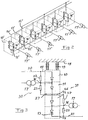
- FIG. 3 illustrates schematically a converter according to an embodiment of the present invention.
- This is also a 12-pulse bridge converter having the series connection of four converter valves 10-13 arranged in one column on top of each other, so that the converter will have three such columns arranged in a row.
- Such a column is here shown to be insulated with respect to the roof 18 of a current valve hall by an insulation member 19.
- the DC-side of the converter is connected to said converter column on opposite sides thereof by a connection 20 to a pole of the HVDC transmission line and the connection 21 to a neutral bus of the converter station.
- Surge arresters 22-25 are connected in series between said DC-connections 20, 21 with one surge arrester connected in parallel with each converter valve for protection thereof against over-voltages.
- One part of the series connection of surge arresters, namely two of them, 22 and 23, is arranged on one side of the converter valve column and the other part on the other side of the column by being interconnected by a conductor 26 leading from one said side to the other through a free space 27 between two said converter valves 11, 12.
- Each converter valve comprises a plurality of superimposed layers comprising power semiconductors, and said free space 27 is preferably formed by leaving a distance between two subsequent converter valves of approximately half such a layer.
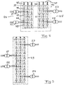
- FIG. 4 shows a further application in which the present invention is useful.
- This figure shows a known back-to-back application, in which two converters 40, 41 are connected by a DC link 42 and arranged in a converter hall 43.
- the alternating voltage may for instance on one side 44 have a frequency of 50 Hz and on the other side 45 a frequency of 60 Hz.
- Each converter has here three columns, one for each phase, each having four converter valves 46-49 as indicated for the column 50.
- the transformers 51-54 connected to the same converter are provided on the same side of the converter, and the converter hall 43 for this arrangement gets rather wide.
- Fig. 5 shows a converter according to the invention used in a back-to-back application as the one according to Fig. 4 .
- This converter uses octuple valves, i.e. eight converter valves in each column, and transformers 51-54 are arranged on both sides of the converter hall 43 by using the technique described above and illustrated in Fig. 3 . This reduces the width of the valve hall considerably.
Landscapes
- Engineering & Computer Science (AREA)
- Power Engineering (AREA)
- Rectifiers (AREA)
- Inverter Devices (AREA)
Claims (16)
- Umsetzer zum Umsetzen einer Wechselspannung in eine Gleichspannung und umgekehrt in einer Umsetzerstation eines Hochspannungsübertragungssystems, wobei der Umsetzer eine Serienschaltung aus mehreren Umsetzerventilen (10-13) umfasst, wobei eine Gleichstromseite des Umsetzers durch gegenüberliegende Enden (14, 15) der Serienschaltung von Umsetzerventilen für den Anschluss an hohes Potential bzw. niedriges Potential gebildet ist, wobei der Umsetzer ferner mehrere Elemente (16) umfasst, die mit einer Wechselstromseite des Umsetzers verbunden sind, indem sie jeweils mit Punkten der Serienschaltung zwischen aufeinander folgenden Umsetzerventilen verbunden sind, um von dem Umsetzer zu Transformatoren (17) herauszuführen, wobei die Serienschaltung wenigstens vier Umsetzerventile (10-13) enthält, die übereinander in einer Spalte angeordnet sind, und wobei die Verbindungselemente (16) mit Punkten der Serienschaltung zwischen jedem zweiten Umsetzerventil, etwa zwischen dem ersten und dem zweiten, dem dritten und dem vierten usw. in der Spalte verbunden sind, dadurch gekennzeichnet, dass
die Verbindungselemente (16) auf zwei gegenüberliegenden Seiten der Spalte angeordnet sind und aus der Spalte herausführen, um mit den Transformatoren zu verbinden, und dadurch, dass
der Umsetzer mehrere Überspannungsableiter (22-25) umfasst, die zwischen den zwei Gleichstromenden (20, 21) der Umsetzerventil-Serienschaltung in Serie geschaltet sind, wobei ein Überspannungsableiter zu jedem Umsetzerventil parallel geschaltet ist, wobei die Serienschaltung aus Überspannungsableitern einen ersten Teil (22, 23), der auf einer Seite (30) der Serienschaltung von Umsetzerventilen angeordnet ist, und einen nachfolgenden zweiten Teil (24, 25), der auf der gegenüberliegenden Seite (31) der Serienschaltung von Umsetzerventilen angeordnet ist, aufweist, wobei die zwei Teile durch einen Leiter (26) miteinander verbunden sind, der von einer Seite zu der anderen über einen freien Raum (27) zwischen zwei Umsetzerventilen führt. - Umsetzer nach Anspruch 1, dadurch gekennzeichnet, dass die Hälfte der Verbindungselemente (16) auf einer Seite der Umsetzerventile (10-13) angeordnet ist und die andere Hälfte auf der anderen Seite hiervon angeordnet ist.
- Umsetzer nach einem vorhergehenden Anspruch, dadurch gekennzeichnet, dass die Serienschaltung von Umsetzerventilen vier Umsetzerventile (10-13) und eines der Verbindungselemente für die Wechselstromseite auf jeder von zwei gegenüberliegenden Seiten der Spalte besitzt.
- Umsetzer nach einem der vorhergehenden Ansprüche, dadurch gekennzeichnet, dass er mehrere Serienschaltungen aus Umsetzerventilen, die zueinander parallel geschaltet sind, umfasst.
- Umsetzer nach Anspruch 4, dadurch gekennzeichnet, dass er drei Serienschaltungen aus Umsetzerventilen (10-13) besitzt, die zueinander parallel geschaltet sind, um auf der Wechselstromseite drei Phasen bereitzustellen.
- Umsetzer nach Anspruch 3 und 5, dadurch gekennzeichnet, dass er drei Spalten aus vier Umsetzerventilen (10-13) umfasst, die in einer Reihe in Serie geschaltet sind, und dass jede Spalte ein Element (16) besitzt, das auf jeder von zwei gegenüberliegenden Seiten der Reihe mit der Wechselstromseite verbindet.
- Umsetzer nach Anspruch 6, dadurch gekennzeichnet, dass jedes Umsetzerventil (10-13) mehrere überlagerte Schichten umfasst, die Leistungshalbleiter enthalten, und dass der freie Raum (27) dadurch gebildet ist, dass zwischen zwei aufeinander Folgenden der Umsetzerventile (11, 12) ein Abstand, der etwa der Hälfte einer solchen Schicht oder einer solchen Schicht entspricht, ausgebildet ist.
- Umsetzer nach einem der vorhergehenden Ansprüche, dadurch gekennzeichnet, dass die zwei gleichstromseitigen Verbindungen (20, 21) mit den gegenüberliegenden Enden der Serienschaltung von Umsetzerventilen auch jeweils auf einer der gegenüberliegenden Seiten der Umsetzerventile (10-13) angeordnet sind.
- Umsetzer nach einem der vorhergehenden Ansprüche, dadurch gekennzeichnet, dass er ein Umsetzerventilgehäuse umfasst, das die Umsetzerventile umschließt, und Durchführungen in gegenüberliegenden Wänden hiervon besitzt, um mit Transformatoren (17) außerhalb des Gehäuses auf gegenüberliegenden Seiten hiervon zu verbinden.
- Umsetzer nach einem der vorhergehenden Ansprüche, dadurch gekennzeichnet, dass er dafür ausgelegt ist, Spannungen auf der Gleichstromseite des Umsetzers oberhalb von 50 kV, oberhalb von 200 kV, oberhalb von 400 kV oder im Bereich von 600 kV bis 1000 kV umzusetzen.
- Umsetzerstation zum Verbinden eines Wechselstromssystems mit einer HVDC-Übertragungsleitung, die mit wenigstens einem Umsetzer nach einem der Ansprüche 1-10 ausgerüstet ist.
- Umsetzerstation zum Verbinden eines Wechselstromsystems mit einem weiteren Wechselstromsystem in einer Kreuzschaltungsanwendung, die mit wenigstens einem Umsetzer nach einem der Ansprüche 1-10 versehen ist.
- HVDC-Übertragungssystem (Hochspannungsgleichstrom- Übertragungssystem), das Umsetzerstationen mit wenigstens einem Umsetzer nach einem der Ansprüche 1-10 besitzt.
- Hochspannungs-Wechselstromübertragungssystem, das eine Umsetzerstation mit wenigstens einem Umsetzer nach einem der Ansprüche 1-10 in einer Kreuzschaltungsanwendung besitzt.
- Verwendung eines Umsetzers nach einem der Ansprüche 1-10 in einer Umsetzerstation eines HVDC- Übertragungssystems.
- Verwendung eines Umsetzers nach einem der Ansprüche 1-10 in einer Kreuzschaltungs-Umsetzerstation eines Hochspannungs-Wechselstromübertragungssystems.
Applications Claiming Priority (2)
| Application Number | Priority Date | Filing Date | Title |
|---|---|---|---|
| US76040006P | 2006-01-20 | 2006-01-20 | |
| PCT/SE2006/000716 WO2007084039A1 (en) | 2006-01-20 | 2006-06-15 | A converter |
Publications (4)
| Publication Number | Publication Date |
|---|---|
| EP1974433A1 EP1974433A1 (de) | 2008-10-01 |
| EP1974433A4 EP1974433A4 (de) | 2013-06-19 |
| EP1974433B1 EP1974433B1 (de) | 2014-09-03 |
| EP1974433B2 true EP1974433B2 (de) | 2018-01-24 |
Family
ID=38287894
Family Applications (1)
| Application Number | Title | Priority Date | Filing Date |
|---|---|---|---|
| EP06747909.7A Not-in-force EP1974433B2 (de) | 2006-01-20 | 2006-06-15 | Wandler |
Country Status (7)
| Country | Link |
|---|---|
| US (1) | US8107266B2 (de) |
| EP (1) | EP1974433B2 (de) |
| CN (1) | CN101297457B (de) |
| BR (1) | BRPI0621040A2 (de) |
| RU (1) | RU2396665C2 (de) |
| WO (1) | WO2007084039A1 (de) |
| ZA (1) | ZA200805666B (de) |
Families Citing this family (6)
| Publication number | Priority date | Publication date | Assignee | Title |
|---|---|---|---|---|
| DE102008007659A1 (de) * | 2008-02-06 | 2009-02-19 | Siemens Aktiengesellschaft | Umrichter |
| CN101752874B (zh) * | 2010-01-25 | 2012-08-08 | 株洲变流技术国家工程研究中心有限公司 | 一种基于可关断器件的移动式输电方法 |
| CN101882792B (zh) * | 2010-06-30 | 2012-08-22 | 国家电网公司 | 一种用于特高压直流输电的接线方法及特高压换流站 |
| CN103119821B (zh) | 2010-09-30 | 2016-01-13 | Abb研究有限公司 | 多端hvdc系统的协调控制 |
| CN202103561U (zh) * | 2011-03-04 | 2012-01-04 | 上海雷诺尔科技股份有限公司 | 适用于高压变频调速器的连接单元 |
| US11355925B2 (en) | 2018-01-30 | 2022-06-07 | Hitachi Energy Switzerland Ag | System design solution for DC grid cost reduction and risk minimization |
Citations (5)
| Publication number | Priority date | Publication date | Assignee | Title |
|---|---|---|---|---|
| DE2537780A1 (de) † | 1975-08-25 | 1977-03-03 | Siemens Ag | Raeumliche anordnung der ventile einer zwoelfpulsigen stromrichteranlage |
| DE3010294C2 (de) † | 1979-03-27 | 1984-07-19 | ASEA AB, Västeraas | Stromrichter |
| DE3404076A1 (de) † | 1984-02-06 | 1985-08-08 | Siemens AG, 1000 Berlin und 8000 München | Gleichstrom-kurzkupplung |
| EP0299275B1 (de) † | 1987-07-13 | 1992-03-11 | Siemens Aktiengesellschaft | Stromrichteranlage zum Kuppeln zweier Hochspannungs-Drehstromnetze |
| WO2007084036A1 (en) † | 2006-01-18 | 2007-07-26 | Abb Technology Ltd. | A converter station |
Family Cites Families (10)
| Publication number | Priority date | Publication date | Assignee | Title |
|---|---|---|---|---|
| AT271630B (de) * | 1966-10-11 | 1969-06-10 | Asea Ab | Stromrichterventil mit Thyristoren |
| DE2360783A1 (de) * | 1973-12-06 | 1975-06-12 | Bbc Brown Boveri & Cie | Erdung einer zweipoligen hochspannungsgleichstrom-uebertragungs-anlage |
| SE405053B (sv) * | 1977-04-05 | 1978-11-13 | Asea Ab | Stromriktare |
| SE463953B (sv) | 1989-06-19 | 1991-02-11 | Asea Brown Boveri | Anlaeggning foer avtappning av elektrisk kraft fraan en hoegspaend likstroemstransmissionslinje |
| SE503398C2 (sv) * | 1994-02-17 | 1996-06-03 | Asea Brown Boveri | Strömriktaranläggning med styrorgan för seriekopplad strömstyv och spänningsstyv strömriktare |
| SE503106C2 (sv) * | 1994-07-01 | 1996-03-25 | Asea Brown Boveri | Lastkommuterad synkronmotordrift |
| DE19523095A1 (de) * | 1995-06-26 | 1997-01-02 | Abb Management Ag | Stromrichterschaltungsanordnung |
| CN2472407Y (zh) * | 2001-04-18 | 2002-01-16 | 吴加林 | 一种局域电网用的节能装置 |
| CN1461088A (zh) * | 2003-06-12 | 2003-12-10 | 清华大学 | 用于链式静止同步补偿器直流电压平衡控制的双向变换器 |
| US7969755B2 (en) * | 2005-09-09 | 2011-06-28 | Siemens Aktiengesellschaft | Apparatus for electrical power transmission |
-
2006
- 2006-06-15 BR BRPI0621040-6A patent/BRPI0621040A2/pt not_active IP Right Cessation
- 2006-06-15 US US12/161,585 patent/US8107266B2/en not_active Expired - Fee Related
- 2006-06-15 CN CN2006800400718A patent/CN101297457B/zh not_active Expired - Fee Related
- 2006-06-15 RU RU2008134114/09A patent/RU2396665C2/ru not_active IP Right Cessation
- 2006-06-15 EP EP06747909.7A patent/EP1974433B2/de not_active Not-in-force
- 2006-06-15 WO PCT/SE2006/000716 patent/WO2007084039A1/en not_active Ceased
-
2008
- 2008-06-27 ZA ZA200805666A patent/ZA200805666B/xx unknown
Patent Citations (5)
| Publication number | Priority date | Publication date | Assignee | Title |
|---|---|---|---|---|
| DE2537780A1 (de) † | 1975-08-25 | 1977-03-03 | Siemens Ag | Raeumliche anordnung der ventile einer zwoelfpulsigen stromrichteranlage |
| DE3010294C2 (de) † | 1979-03-27 | 1984-07-19 | ASEA AB, Västeraas | Stromrichter |
| DE3404076A1 (de) † | 1984-02-06 | 1985-08-08 | Siemens AG, 1000 Berlin und 8000 München | Gleichstrom-kurzkupplung |
| EP0299275B1 (de) † | 1987-07-13 | 1992-03-11 | Siemens Aktiengesellschaft | Stromrichteranlage zum Kuppeln zweier Hochspannungs-Drehstromnetze |
| WO2007084036A1 (en) † | 2006-01-18 | 2007-07-26 | Abb Technology Ltd. | A converter station |
Non-Patent Citations (1)
| Title |
|---|
| Prio US 60/759,564 † |
Also Published As
| Publication number | Publication date |
|---|---|
| CN101297457A (zh) | 2008-10-29 |
| RU2396665C2 (ru) | 2010-08-10 |
| BRPI0621040A2 (pt) | 2011-11-29 |
| ZA200805666B (en) | 2009-04-29 |
| WO2007084039A1 (en) | 2007-07-26 |
| US20090303758A1 (en) | 2009-12-10 |
| EP1974433A1 (de) | 2008-10-01 |
| CN101297457B (zh) | 2011-08-10 |
| EP1974433A4 (de) | 2013-06-19 |
| US8107266B2 (en) | 2012-01-31 |
| EP1974433B1 (de) | 2014-09-03 |
| RU2008134114A (ru) | 2010-02-27 |
Similar Documents
| Publication | Publication Date | Title |
|---|---|---|
| EP2289163B1 (de) | Spannungsquellenumsetzer | |
| EP2266137B1 (de) | U-umrichter | |
| JP5977282B2 (ja) | マルチレベルインバータ | |
| CN105556787B (zh) | 用于高电压的模块化多点变流器 | |
| JP4502510B2 (ja) | Vsc変換装置 | |
| US8098504B2 (en) | Converter station for connecting an AC system to an end of an HVDC transmission line | |
| KR101373170B1 (ko) | 컨버터 | |
| EP2294684B1 (de) | Anlage zum übertragen von elektrischem strom | |
| CN109075722B (zh) | 变流器装置 | |
| EP1974433B2 (de) | Wandler | |
| US5870300A (en) | Voltage converter having a commutation circuit with reduced inductance | |
| CA2915400C (en) | A power converter with oil filled reactors | |
| CN102084585B (zh) | 用于电压转换的装置 | |
| CN206117493U (zh) | 具有电涌放电器的电力转换器 | |
| US5896285A (en) | Apparatus for interconnection in voltage-stiff converter devices | |
| JPH11164421A (ja) | 交直変換設備 | |
| CN104253539A (zh) | 电力转换装置 |
Legal Events
| Date | Code | Title | Description |
|---|---|---|---|
| PUAI | Public reference made under article 153(3) epc to a published international application that has entered the european phase |
Free format text: ORIGINAL CODE: 0009012 |
|
| 17P | Request for examination filed |
Effective date: 20080623 |
|
| AK | Designated contracting states |
Kind code of ref document: A1 Designated state(s): AT BE BG CH CY CZ DE DK EE ES FI FR GB GR HU IE IS IT LI LT LU LV MC NL PL PT RO SE SI SK TR |
|
| DAX | Request for extension of the european patent (deleted) | ||
| A4 | Supplementary search report drawn up and despatched |
Effective date: 20130523 |
|
| RIC1 | Information provided on ipc code assigned before grant |
Ipc: H02M 1/00 20070101ALI20130516BHEP Ipc: H02M 7/757 20060101ALI20130516BHEP Ipc: H02J 3/36 20060101AFI20130516BHEP |
|
| GRAP | Despatch of communication of intention to grant a patent |
Free format text: ORIGINAL CODE: EPIDOSNIGR1 |
|
| RIC1 | Information provided on ipc code assigned before grant |
Ipc: H02J 3/36 20060101AFI20140327BHEP Ipc: H02M 1/00 20070101ALI20140327BHEP Ipc: H02M 7/757 20060101ALI20140327BHEP |
|
| INTG | Intention to grant announced |
Effective date: 20140414 |
|
| GRAS | Grant fee paid |
Free format text: ORIGINAL CODE: EPIDOSNIGR3 |
|
| GRAA | (expected) grant |
Free format text: ORIGINAL CODE: 0009210 |
|
| AK | Designated contracting states |
Kind code of ref document: B1 Designated state(s): AT BE BG CH CY CZ DE DK EE ES FI FR GB GR HU IE IS IT LI LT LU LV MC NL PL PT RO SE SI SK TR |
|
| REG | Reference to a national code |
Ref country code: GB Ref legal event code: FG4D |
|
| REG | Reference to a national code |
Ref country code: CH Ref legal event code: EP Ref country code: AT Ref legal event code: REF Ref document number: 686030 Country of ref document: AT Kind code of ref document: T Effective date: 20140915 |
|
| REG | Reference to a national code |
Ref country code: IE Ref legal event code: FG4D |
|
| REG | Reference to a national code |
Ref country code: DE Ref legal event code: R096 Ref document number: 602006042928 Country of ref document: DE Effective date: 20141016 |
|
| REG | Reference to a national code |
Ref country code: SE Ref legal event code: TRGR |
|
| REG | Reference to a national code |
Ref country code: AT Ref legal event code: MK05 Ref document number: 686030 Country of ref document: AT Kind code of ref document: T Effective date: 20140903 |
|
| PG25 | Lapsed in a contracting state [announced via postgrant information from national office to epo] |
Ref country code: GR Free format text: LAPSE BECAUSE OF FAILURE TO SUBMIT A TRANSLATION OF THE DESCRIPTION OR TO PAY THE FEE WITHIN THE PRESCRIBED TIME-LIMIT Effective date: 20141204 Ref country code: LT Free format text: LAPSE BECAUSE OF FAILURE TO SUBMIT A TRANSLATION OF THE DESCRIPTION OR TO PAY THE FEE WITHIN THE PRESCRIBED TIME-LIMIT Effective date: 20140903 Ref country code: FI Free format text: LAPSE BECAUSE OF FAILURE TO SUBMIT A TRANSLATION OF THE DESCRIPTION OR TO PAY THE FEE WITHIN THE PRESCRIBED TIME-LIMIT Effective date: 20140903 Ref country code: ES Free format text: LAPSE BECAUSE OF FAILURE TO SUBMIT A TRANSLATION OF THE DESCRIPTION OR TO PAY THE FEE WITHIN THE PRESCRIBED TIME-LIMIT Effective date: 20140903 |
|
| REG | Reference to a national code |
Ref country code: NL Ref legal event code: VDEP Effective date: 20140903 |
|
| REG | Reference to a national code |
Ref country code: LT Ref legal event code: MG4D |
|
| PG25 | Lapsed in a contracting state [announced via postgrant information from national office to epo] |
Ref country code: LV Free format text: LAPSE BECAUSE OF FAILURE TO SUBMIT A TRANSLATION OF THE DESCRIPTION OR TO PAY THE FEE WITHIN THE PRESCRIBED TIME-LIMIT Effective date: 20140903 Ref country code: AT Free format text: LAPSE BECAUSE OF FAILURE TO SUBMIT A TRANSLATION OF THE DESCRIPTION OR TO PAY THE FEE WITHIN THE PRESCRIBED TIME-LIMIT Effective date: 20140903 Ref country code: CY Free format text: LAPSE BECAUSE OF FAILURE TO SUBMIT A TRANSLATION OF THE DESCRIPTION OR TO PAY THE FEE WITHIN THE PRESCRIBED TIME-LIMIT Effective date: 20140903 |
|
| PG25 | Lapsed in a contracting state [announced via postgrant information from national office to epo] |
Ref country code: NL Free format text: LAPSE BECAUSE OF FAILURE TO SUBMIT A TRANSLATION OF THE DESCRIPTION OR TO PAY THE FEE WITHIN THE PRESCRIBED TIME-LIMIT Effective date: 20140903 |
|
| PG25 | Lapsed in a contracting state [announced via postgrant information from national office to epo] |
Ref country code: RO Free format text: LAPSE BECAUSE OF FAILURE TO SUBMIT A TRANSLATION OF THE DESCRIPTION OR TO PAY THE FEE WITHIN THE PRESCRIBED TIME-LIMIT Effective date: 20140903 Ref country code: IS Free format text: LAPSE BECAUSE OF FAILURE TO SUBMIT A TRANSLATION OF THE DESCRIPTION OR TO PAY THE FEE WITHIN THE PRESCRIBED TIME-LIMIT Effective date: 20150103 Ref country code: EE Free format text: LAPSE BECAUSE OF FAILURE TO SUBMIT A TRANSLATION OF THE DESCRIPTION OR TO PAY THE FEE WITHIN THE PRESCRIBED TIME-LIMIT Effective date: 20140903 Ref country code: PT Free format text: LAPSE BECAUSE OF FAILURE TO SUBMIT A TRANSLATION OF THE DESCRIPTION OR TO PAY THE FEE WITHIN THE PRESCRIBED TIME-LIMIT Effective date: 20150105 Ref country code: CZ Free format text: LAPSE BECAUSE OF FAILURE TO SUBMIT A TRANSLATION OF THE DESCRIPTION OR TO PAY THE FEE WITHIN THE PRESCRIBED TIME-LIMIT Effective date: 20140903 Ref country code: SK Free format text: LAPSE BECAUSE OF FAILURE TO SUBMIT A TRANSLATION OF THE DESCRIPTION OR TO PAY THE FEE WITHIN THE PRESCRIBED TIME-LIMIT Effective date: 20140903 |
|
| PG25 | Lapsed in a contracting state [announced via postgrant information from national office to epo] |
Ref country code: PL Free format text: LAPSE BECAUSE OF FAILURE TO SUBMIT A TRANSLATION OF THE DESCRIPTION OR TO PAY THE FEE WITHIN THE PRESCRIBED TIME-LIMIT Effective date: 20140903 |
|
| REG | Reference to a national code |
Ref country code: DE Ref legal event code: R026 Ref document number: 602006042928 Country of ref document: DE |
|
| PLBI | Opposition filed |
Free format text: ORIGINAL CODE: 0009260 |
|
| REG | Reference to a national code |
Ref country code: FR Ref legal event code: PLFP Year of fee payment: 10 |
|
| PLAX | Notice of opposition and request to file observation + time limit sent |
Free format text: ORIGINAL CODE: EPIDOSNOBS2 |
|
| 26 | Opposition filed |
Opponent name: SIEMENS AKTIENGESELLSCHAFT Effective date: 20150601 |
|
| PG25 | Lapsed in a contracting state [announced via postgrant information from national office to epo] |
Ref country code: DK Free format text: LAPSE BECAUSE OF FAILURE TO SUBMIT A TRANSLATION OF THE DESCRIPTION OR TO PAY THE FEE WITHIN THE PRESCRIBED TIME-LIMIT Effective date: 20140903 |
|
| PG25 | Lapsed in a contracting state [announced via postgrant information from national office to epo] |
Ref country code: IT Free format text: LAPSE BECAUSE OF FAILURE TO SUBMIT A TRANSLATION OF THE DESCRIPTION OR TO PAY THE FEE WITHIN THE PRESCRIBED TIME-LIMIT Effective date: 20140903 |
|
| PLAF | Information modified related to communication of a notice of opposition and request to file observations + time limit |
Free format text: ORIGINAL CODE: EPIDOSCOBS2 |
|
| PG25 | Lapsed in a contracting state [announced via postgrant information from national office to epo] |
Ref country code: SI Free format text: LAPSE BECAUSE OF FAILURE TO SUBMIT A TRANSLATION OF THE DESCRIPTION OR TO PAY THE FEE WITHIN THE PRESCRIBED TIME-LIMIT Effective date: 20140903 |
|
| PLBB | Reply of patent proprietor to notice(s) of opposition received |
Free format text: ORIGINAL CODE: EPIDOSNOBS3 |
|
| PG25 | Lapsed in a contracting state [announced via postgrant information from national office to epo] |
Ref country code: MC Free format text: LAPSE BECAUSE OF FAILURE TO SUBMIT A TRANSLATION OF THE DESCRIPTION OR TO PAY THE FEE WITHIN THE PRESCRIBED TIME-LIMIT Effective date: 20140903 |
|
| REG | Reference to a national code |
Ref country code: CH Ref legal event code: PL |
|
| PG25 | Lapsed in a contracting state [announced via postgrant information from national office to epo] |
Ref country code: LU Free format text: LAPSE BECAUSE OF FAILURE TO SUBMIT A TRANSLATION OF THE DESCRIPTION OR TO PAY THE FEE WITHIN THE PRESCRIBED TIME-LIMIT Effective date: 20150615 |
|
| REG | Reference to a national code |
Ref country code: IE Ref legal event code: MM4A |
|
| PG25 | Lapsed in a contracting state [announced via postgrant information from national office to epo] |
Ref country code: IE Free format text: LAPSE BECAUSE OF NON-PAYMENT OF DUE FEES Effective date: 20150615 Ref country code: CH Free format text: LAPSE BECAUSE OF NON-PAYMENT OF DUE FEES Effective date: 20150630 Ref country code: LI Free format text: LAPSE BECAUSE OF NON-PAYMENT OF DUE FEES Effective date: 20150630 |
|
| REG | Reference to a national code |
Ref country code: FR Ref legal event code: PLFP Year of fee payment: 11 |
|
| PG25 | Lapsed in a contracting state [announced via postgrant information from national office to epo] |
Ref country code: BE Free format text: LAPSE BECAUSE OF FAILURE TO SUBMIT A TRANSLATION OF THE DESCRIPTION OR TO PAY THE FEE WITHIN THE PRESCRIBED TIME-LIMIT Effective date: 20140903 |
|
| REG | Reference to a national code |
Ref country code: DE Ref legal event code: R081 Ref document number: 602006042928 Country of ref document: DE Owner name: ABB SCHWEIZ AG, CH Free format text: FORMER OWNER: ABB TECHNOLOGY LTD., ZUERICH, CH |
|
| RAP2 | Party data changed (patent owner data changed or rights of a patent transferred) |
Owner name: ABB SCHWEIZ AG |
|
| PG25 | Lapsed in a contracting state [announced via postgrant information from national office to epo] |
Ref country code: HU Free format text: LAPSE BECAUSE OF FAILURE TO SUBMIT A TRANSLATION OF THE DESCRIPTION OR TO PAY THE FEE WITHIN THE PRESCRIBED TIME-LIMIT; INVALID AB INITIO Effective date: 20060615 Ref country code: BG Free format text: LAPSE BECAUSE OF FAILURE TO SUBMIT A TRANSLATION OF THE DESCRIPTION OR TO PAY THE FEE WITHIN THE PRESCRIBED TIME-LIMIT Effective date: 20140903 |
|
| REG | Reference to a national code |
Ref country code: FR Ref legal event code: PLFP Year of fee payment: 12 |
|
| PG25 | Lapsed in a contracting state [announced via postgrant information from national office to epo] |
Ref country code: TR Free format text: LAPSE BECAUSE OF FAILURE TO SUBMIT A TRANSLATION OF THE DESCRIPTION OR TO PAY THE FEE WITHIN THE PRESCRIBED TIME-LIMIT Effective date: 20140903 |
|
| PGFP | Annual fee paid to national office [announced via postgrant information from national office to epo] |
Ref country code: SE Payment date: 20170620 Year of fee payment: 12 |
|
| PLAB | Opposition data, opponent's data or that of the opponent's representative modified |
Free format text: ORIGINAL CODE: 0009299OPPO |
|
| R26 | Opposition filed (corrected) |
Opponent name: SIEMENS AKTIENGESELLSCHAFT Effective date: 20150601 |
|
| PUAH | Patent maintained in amended form |
Free format text: ORIGINAL CODE: 0009272 |
|
| STAA | Information on the status of an ep patent application or granted ep patent |
Free format text: STATUS: PATENT MAINTAINED AS AMENDED |
|
| 27A | Patent maintained in amended form |
Effective date: 20180124 |
|
| AK | Designated contracting states |
Kind code of ref document: B2 Designated state(s): AT BE BG CH CY CZ DE DK EE ES FI FR GB GR HU IE IS IT LI LT LU LV MC NL PL PT RO SE SI SK TR |
|
| REG | Reference to a national code |
Ref country code: DE Ref legal event code: R102 Ref document number: 602006042928 Country of ref document: DE |
|
| REG | Reference to a national code |
Ref country code: GB Ref legal event code: 732E Free format text: REGISTERED BETWEEN 20180426 AND 20180502 |
|
| REG | Reference to a national code |
Ref country code: FR Ref legal event code: PLFP Year of fee payment: 13 |
|
| REG | Reference to a national code |
Ref country code: SE Ref legal event code: NAV |
|
| PG25 | Lapsed in a contracting state [announced via postgrant information from national office to epo] |
Ref country code: SE Free format text: LAPSE BECAUSE OF NON-PAYMENT OF DUE FEES Effective date: 20180615 |
|
| PGFP | Annual fee paid to national office [announced via postgrant information from national office to epo] |
Ref country code: DE Payment date: 20200618 Year of fee payment: 15 Ref country code: FR Payment date: 20200619 Year of fee payment: 15 |
|
| PGFP | Annual fee paid to national office [announced via postgrant information from national office to epo] |
Ref country code: GB Payment date: 20200625 Year of fee payment: 15 |
|
| REG | Reference to a national code |
Ref country code: DE Ref legal event code: R119 Ref document number: 602006042928 Country of ref document: DE |
|
| GBPC | Gb: european patent ceased through non-payment of renewal fee |
Effective date: 20210615 |
|
| PG25 | Lapsed in a contracting state [announced via postgrant information from national office to epo] |
Ref country code: GB Free format text: LAPSE BECAUSE OF NON-PAYMENT OF DUE FEES Effective date: 20210615 Ref country code: DE Free format text: LAPSE BECAUSE OF NON-PAYMENT OF DUE FEES Effective date: 20220101 |
|
| PG25 | Lapsed in a contracting state [announced via postgrant information from national office to epo] |
Ref country code: FR Free format text: LAPSE BECAUSE OF NON-PAYMENT OF DUE FEES Effective date: 20210630 |