EP1975106A2 - Tension de fil - Google Patents
Tension de fil Download PDFInfo
- Publication number
- EP1975106A2 EP1975106A2 EP08450041A EP08450041A EP1975106A2 EP 1975106 A2 EP1975106 A2 EP 1975106A2 EP 08450041 A EP08450041 A EP 08450041A EP 08450041 A EP08450041 A EP 08450041A EP 1975106 A2 EP1975106 A2 EP 1975106A2
- Authority
- EP
- European Patent Office
- Prior art keywords
- winding
- spring
- dancer
- unit
- winding unit
- Prior art date
- Legal status (The legal status is an assumption and is not a legal conclusion. Google has not performed a legal analysis and makes no representation as to the accuracy of the status listed.)
- Granted
Links
Images



Classifications
-
- B—PERFORMING OPERATIONS; TRANSPORTING
- B65—CONVEYING; PACKING; STORING; HANDLING THIN OR FILAMENTARY MATERIAL
- B65H—HANDLING THIN OR FILAMENTARY MATERIAL, e.g. SHEETS, WEBS, CABLES
- B65H59/00—Adjusting or controlling tension in filamentary material, e.g. for preventing snarling; Applications of tension indicators
- B65H59/10—Adjusting or controlling tension in filamentary material, e.g. for preventing snarling; Applications of tension indicators by devices acting on running material and not associated with supply or take-up devices
- B65H59/36—Floating elements compensating for irregularities in supply or take-up of material
-
- B—PERFORMING OPERATIONS; TRANSPORTING
- B65—CONVEYING; PACKING; STORING; HANDLING THIN OR FILAMENTARY MATERIAL
- B65H—HANDLING THIN OR FILAMENTARY MATERIAL, e.g. SHEETS, WEBS, CABLES
- B65H59/00—Adjusting or controlling tension in filamentary material, e.g. for preventing snarling; Applications of tension indicators
- B65H59/38—Adjusting or controlling tension in filamentary material, e.g. for preventing snarling; Applications of tension indicators by regulating speed of driving mechanism of unwinding, paying-out, forwarding, winding, or depositing devices, e.g. automatically in response to variations in tension
- B65H59/384—Adjusting or controlling tension in filamentary material, e.g. for preventing snarling; Applications of tension indicators by regulating speed of driving mechanism of unwinding, paying-out, forwarding, winding, or depositing devices, e.g. automatically in response to variations in tension using electronic means
- B65H59/385—Regulating winding speed
-
- B—PERFORMING OPERATIONS; TRANSPORTING
- B65—CONVEYING; PACKING; STORING; HANDLING THIN OR FILAMENTARY MATERIAL
- B65H—HANDLING THIN OR FILAMENTARY MATERIAL, e.g. SHEETS, WEBS, CABLES
- B65H2701/00—Handled material; Storage means
- B65H2701/30—Handled filamentary material
- B65H2701/31—Textiles threads or artificial strands of filaments
Definitions
- the invention relates to a method for controlling the thread tension when winding tape or filamentary material on a winding machine, which has a number of winding units, and for each winding unit, the winding material is fed via a dancer roll sitting on a driven by a motor winding spindle spool , wherein the position of the displaceable against the force of a spring dancer roller is detected by a position sensor, the output of the position sensor as an actual value signal and a reference value as a setpoint signal to a control amplifier are supplied, and the output of the variable gain amplifier of the motor is driven so that to a constant position the dancer role is regulated.
- the invention relates to a winding unit for a winding, for winding tape or filamentary good, with a, driven by a motor winding spindle, a yarn guide and a dancer roll, wherein the stationary winding spindle is adapted to receive a winding tube, which is on the dancer roller and the yarn guide guided Spulgut is wound up, with a the position of the displaceable against the force of a spring dancer roller position sensor, a variable gain amplifier, the output of the position sensor is fed as the actual value signal and a reference value as a setpoint signal, wherein the output signal of the variable gain amplifier to a motor driver is fed so that a constant position of the dancer roll is maintained.
- Spooled goods which are produced and delivered, for example, by a production apparatus, such as a plurality of plastic belts, which are produced by an extruding machine, are usually wound up on a large number of supply spools at the same time.
- the maintenance of a given thread tension is very important, because this thread tension determines on the one hand the strength of the finished bobbins and on the other hand must never be so large that it comes to a tearing of the thread or tape, resulting in at least material loss, if not to production losses can.
- An object of the invention is to provide a method or a winding unit in which a sufficiently movable dancer roll is present, a thread tension control takes place and the thread tension can be predetermined centrally. This task comes with a Solved method of the type mentioned, in which according to the invention, the control over the drive torque of the motor takes place.
- control takes place here via the drive torque of the motor.
- the dancer roll has a lot of room to move
- the position of a dancer arm carrying the dancer roll is detected by means of a position sensor detecting its pivoting and designed as an angle encoder.
- the object is also achieved with a winding unit of the type mentioned, in which according to the invention the bias of the spring is kept constant and for adjusting the thread tension of each winding unit, the reference value can be predetermined by a central control and control unit of the winding machine.
- a compact variant is characterized in that the dancer roll sits at the outer end of a coil spring whose inner end is stationary. In this case, the axis of the spiral fields substantially coincide with the pivot axis of a yarn guide unit.
- the spring has a different material thickness over its length in order to influence its progression.
- the spring is designed as a leaf / coil spring and at least over a portion of its length has a longitudinally converging longitudinal slot.
- a special mobility of the dancer roll is obtained when the dancer roll sits at the free end of a dancer arm in a winding unit. In this case, it is useful for influencing the progression when the spring is designed as a tension spring and engages an additional lever arm of the dancer arm.
- the spring is realized by a magnet arrangement.
- an expedient embodiment is characterized in that the magnet arrangement has a first, arranged on the dancer arm permanent magnet and a second, fixedly arranged permanent magnet, wherein the magnets are poled in the sense of a repulsive force.
- the position sensor may be formed as the position of the dancer arm in the entanglement detecting angle encoder.
- the position sensor is designed as the displacement of the dancer roll detecting distance sensor.
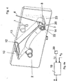
- a winding spindle 2 is arranged on a base plate 1, which accommodates a winding tube 3 and can be driven in a known manner by a drive not shown here.
- a winding tube 3 is shown in the illustration Fig. 1 already so much her fed ribbon or thread-shaped winding material 4 wound that the coil formed in this way 5 is almost fully wound.
- the Spulgut 4 is, for example coming from an extrusion line, the coil 5 via a stationary guide roller 6, a sitting at the end of a dancer arm 7 dancer roller 8 and a further guide roller 9 and finally a yarn guide 10 is supplied.
- the yarn guide 10 protrudes out of a slot 11 of a yarn guide unit 12 and performs a reciprocating motion during winding, which is controlled in a known manner as a function of the spindle rotation and the coil diameter according to specifiable functions to a desired winding. such as As a precise cross winding to get.
- the tension of the thread or the Spulgutes 4 is controlled as well as the speed of the spindle 2 according to the speed of the supplied Spulgutes.
- the yarn speed is in modern systems z. B. up to 600 m / s at spindle speeds up to 4000 U / min.
- winding unit In the Fig. 1 shown and previously briefly described winding unit is referred to as a whole with 13 and a rewinder has a large number, often several hundred such winding units 13.
- the dancer roll 8 is loaded via the dancer arm 7 by the force of a spring 14, which is only indicated in the embodiment shown and, for example, lies within a spring housing 15.
- the spring 14 may be a coiled torsion spring, but it may also be designed as a tension spring, which is arranged for example on the rear side of the base plate 1.
- the pivot axis a of the thread guide unit 12 coincides in this embodiment with the pivot axis a 'of the dancer arm 7.
- the spindle 2 of the unit 13 is driven by a motor 17, one of a motor driver 18 powered electric motor, whose speed or torque, for example, the frequency of its supply voltage and / or the height is proportional.
- the motor driver 18, for example a frequency converter, is in turn driven by the output signal s of a control amplifier 19.
- the pivoting of the dancer arm 7 and the dancer roller 8 is detected in this embodiment by a trained as an angle sensor position sensor 20, the output signal ⁇ is fed to the variable gain amplifier 19 as an actual value.
- the values for the yarn tension are extremely broad, depending on the material and the thickness of the yarn or belt as well as the speed and the possible braking and acceleration processes. In practice, these values of thread tension - given in weight load - between 20 and 1000 grams, corresponding to 0.2 to 10 N.
- a linear dependence of the force on the dancer roll 8 of their displacement will therefore be desirable only in a few cases, so that a certain progression, z. B. approximately logarithmic, is preferable.
- This progression can be achieved by a corresponding coupling of the spring to the dancer roll and / or by a special embodiment of the spring.
- FIG. 3 In training after Fig. 2 is a progression, such.
- Fig. 3 represented, determined by the additional lever arm 16 and the position and connection of the tension spring 14 to this. It can be seen that slight deflections of the arms 7 and 16 lead from their boldly drawn rest position only to small forces, with increasing deflection by an angle ⁇ , the force F but disproportionately increases.
- Fig. 2 Coming back to the desired regulation of the thread tension or force F one looks Fig. 2 in that the output signal of the position sensor 20 is supplied to an input of the control amplifier 19 as the actual value i ⁇ of the swivel angle a and thus - via the characteristic of the Fig. 3 - The thread tension F is supplied.
- the setpoint value s ⁇ receives the control amplifier 19 at a second input from a central computing and control unit 21, which also supplies corresponding setpoints to the other, not shown here winding units.
- the central arithmetic and control unit 21 advantageously the spring characteristic or the force / travel characteristic for the dancer coil of the winding unit is stored, so that when entering a desired thread tension on this characteristic a certain angle ⁇ is specified.
- the target value s ⁇ and taking into account the actual value i ⁇ via the variable gain amplifier 19, the motor driver 18, the Spulgut (thread) 4 and the position sensor 20 for the dancer roll 8 always to a constant position of the dancer roll and thus the associated thread tension regulated.
- the dancer roller 8 is not arranged on a dancer arm, but it is rotatably seated at the outer end of a spring 14 designed as a spiral spring, the inner end of which is stationary relative to the base plate 1, for example clamped on a bolt 22.
- the axis a "of the spiral spring 14 expediently coincides with the swivel axis a of the thread guide unit
- a position sensor 22, which rests on a web 23 protruding from the base plate 1 is designed as a distance sensor and detects the distance ⁇ here over a constant distance ⁇ Controlled to constant thread tension, ie the control amplifier 19, an actual value i ⁇ from the position sensor 20 and a setpoint s ⁇ supplied from the central computing and control unit 21.
- the function of this embodiment is thus in principle the same as in that of Fig. 2 , wherein the force / displacement characteristic is made progressive by the winding or unwinding of the coil spring.
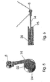
- Fig. 5 shows a further practical design of a spring 14. It is a spring leaf, with one end in a stationary pin 22 (see Fig. 4 ) is clamped about 180 ° around the bolt and then, at least in the load condition shown, straight. At the free end of the spring 14 in turn sits a rotatably mounted dancer roller 8.
- a converging longitudinal slot 24 changed by the non-constant thickness (in the transverse direction), in principle, at least largely linear characteristic of the spring 14, which under load over a widening angular range of the Scope of the bolt 22 is supported, in the sense of the most desired progression.
- Fig. 6 shows the spring 14 as a stretched leaf spring, which is clamped at one end in a stationary support 25 and at its free end the Dancer role 8 carries.
- the characteristic can be made progressive, z. B. by a curved rolling surface 26, on which a portion of the spring 14 can roll and which determines the progression.
- the progression could be defined by a two-layered construction using different spring materials.
- a position sensor 20 which detects a change in the distance of the spring or the dancer roll.
- a position sensor 20 is in Fig. 6 located.
- position encoders whether angle encoders or displacement encoders, a large number of commercially available products are available to the person skilled in the art, some of which work without contact and supply the actual signal for the variable gain amplifier 19.
- Fig. 7 the formation of the spring 14 using a magnet assembly.
- the dancer arm 7 is pivotable about the pivot axis a 'and carries at its free end the dancer roll 8.
- a magnet arrangement which consists in this example of a first, sitting on the dancer arm 7 permanent magnet 27 and a second, fixedly arranged magnet 28.
- the polarity of the magnets 27 and 28 is here chosen so that a repulsive force acts on the dancer arm 7, in the drawing down or on the axis a 'relative - counterclockwise.
Landscapes
- Tension Adjustment In Filamentary Materials (AREA)
Applications Claiming Priority (1)
| Application Number | Priority Date | Filing Date | Title |
|---|---|---|---|
| AT4682007 | 2007-03-26 |
Publications (3)
| Publication Number | Publication Date |
|---|---|
| EP1975106A2 true EP1975106A2 (fr) | 2008-10-01 |
| EP1975106A3 EP1975106A3 (fr) | 2009-10-21 |
| EP1975106B1 EP1975106B1 (fr) | 2012-07-18 |
Family
ID=39535421
Family Applications (1)
| Application Number | Title | Priority Date | Filing Date |
|---|---|---|---|
| EP20080450041 Active EP1975106B1 (fr) | 2007-03-26 | 2008-03-26 | Tension de fil |
Country Status (1)
| Country | Link |
|---|---|
| EP (1) | EP1975106B1 (fr) |
Cited By (17)
| Publication number | Priority date | Publication date | Assignee | Title |
|---|---|---|---|---|
| CN101885434A (zh) * | 2009-05-13 | 2010-11-17 | 欧瑞康纺织有限及两合公司 | 用于自由端纺纱机的工作站的储纱器 |
| CN104860122A (zh) * | 2015-05-25 | 2015-08-26 | 苏州爱立方服饰有限公司 | 纱线换线棒用卷绕生产线 |
| CN106006215A (zh) * | 2016-07-18 | 2016-10-12 | 吴江福爱梁纺织有限公司 | 叠层配重式张力控制装置 |
| WO2016197158A1 (fr) | 2015-06-11 | 2016-12-15 | Bsw Machinery Handels-Gmbh | Bobineuse servant à enrouler un produit à bobiner |
| CN108069289A (zh) * | 2016-11-14 | 2018-05-25 | 索若德国两合股份有限公司 | 用于机械纱线蓄能器的纱线偏转辊 |
| EP3333106A1 (fr) * | 2016-12-12 | 2018-06-13 | Siemens Aktiengesellschaft | Procédé d'enroulement d'un matériau d'enroulement, dispositif de commande, produit-programme informatique et machine à enrouler |
| CN109264505A (zh) * | 2018-08-23 | 2019-01-25 | 苏州创易技研股份有限公司 | 适用于主动/被动送线模式的张力控制器及其控制方法 |
| CN112047199A (zh) * | 2020-08-19 | 2020-12-08 | 何泽江 | 一种电缆收线机收线口处电线张力调节保护装置 |
| CN112158674A (zh) * | 2020-10-27 | 2021-01-01 | 宁波玻尔新材料科技有限公司 | 一种纱线防绕张力自动随速调节器 |
| CN112239104A (zh) * | 2019-07-16 | 2021-01-19 | 科迈士瑞士股份有限公司 | 线缆输送装置、线缆加工系统和将线缆输送给线缆加工机的方法 |
| CN112408094A (zh) * | 2020-11-18 | 2021-02-26 | 胡少坤 | 一种收线缓冲器、收线装置及方法 |
| CN113291926A (zh) * | 2021-06-07 | 2021-08-24 | 上海电气集团自动化工程有限公司 | 一种碳纤维自动铺丝机恒张力送退丝控制系统及控制方法 |
| CN114955723A (zh) * | 2022-06-21 | 2022-08-30 | 西安英利科电气科技有限公司 | 一种采用重力的纱线恒张力装置 |
| US20220396452A1 (en) * | 2021-06-10 | 2022-12-15 | Honda Motor Co., Ltd. | Filament winding method and filament winding apparatus |
| CN116835398A (zh) * | 2023-08-30 | 2023-10-03 | 之江实验室 | 系留线缆的收放控制方法、收放控制装置及飞行器组件 |
| CN117509317A (zh) * | 2023-10-29 | 2024-02-06 | 常熟市电热合金材料厂有限公司 | 一种具有速度和张力控制功能的绕线机 |
| LU504310B1 (de) * | 2023-05-25 | 2024-11-25 | Saurer Spinning Solutions Gmbh & Co Kg | Verfahren zur Steuerung und Regelung eines Wickelwellenantriebs |
Families Citing this family (3)
| Publication number | Priority date | Publication date | Assignee | Title |
|---|---|---|---|---|
| CN104773612A (zh) * | 2015-03-23 | 2015-07-15 | 江苏占姆士纺织有限公司 | 新型补偿式纱线退绕装置 |
| CN104773615A (zh) * | 2015-04-01 | 2015-07-15 | 江苏港宏电线电缆有限公司 | 一种可控制放线速度的被动张力放线架 |
| LU102827B1 (de) * | 2021-06-10 | 2022-12-12 | Saurer Spinning Solutions Gmbh & Co Kg | Fadenspeichereinheit für eine Arbeitsstelle einer Textilmaschine |
Citations (2)
| Publication number | Priority date | Publication date | Assignee | Title |
|---|---|---|---|---|
| CH481002A (de) | 1967-12-01 | 1969-11-15 | Elektromat Veb | Einrichtung zum Ausgleichen der Spannung beim Wickeln von Drähten, Fäden oder dergleichen Wickelmaterial |
| US20050066688A1 (en) | 2003-09-25 | 2005-03-31 | Wolfgang Eis | Device and method for making up optical fibers |
Family Cites Families (8)
| Publication number | Priority date | Publication date | Assignee | Title |
|---|---|---|---|---|
| DE3241362C2 (de) * | 1982-11-09 | 1984-11-29 | A. Ott, Gmbh, 8960 Kempten | Fadenspannungsregler |
| US4566646A (en) * | 1984-05-11 | 1986-01-28 | Leesona Corporation | Take-up machine motor control |
| DE8516286U1 (de) * | 1985-06-04 | 1986-10-02 | F.M.N. Schuster GmbH & Co KG, 5030 Hürth | Vorrichtung zum Zuführen von Fäden, Garnen u. dgl. zu einer Spulvorrichtung |
| US4880175A (en) * | 1987-04-14 | 1989-11-14 | Murata Kikai Kabushiki Kaisha | Tension setting and controlling method and apparatus in an automatic winder |
| US5277373A (en) * | 1991-12-18 | 1994-01-11 | Morton Henry H | Apparatus and method for controlling tension in a moving material |
| WO1995033671A2 (fr) * | 1994-06-06 | 1995-12-14 | Barmag-Spinnzwirn Gmbh | Bobineuse pour fil achemine a vitesse constante |
| FI97795C (fi) * | 1995-07-06 | 1997-02-25 | Maillefer Nokia Holding | Menetelmä ja sovitelma kaapelin tai vastaavan varaajan yhteydessä |
| EP0937007B1 (fr) * | 1996-11-07 | 2002-06-12 | Barmag-Spinnzwirn GmbH | Procede et dispositif de bobinage d'un fil arrivant a une vitesse constante |
-
2008
- 2008-03-26 EP EP20080450041 patent/EP1975106B1/fr active Active
Patent Citations (2)
| Publication number | Priority date | Publication date | Assignee | Title |
|---|---|---|---|---|
| CH481002A (de) | 1967-12-01 | 1969-11-15 | Elektromat Veb | Einrichtung zum Ausgleichen der Spannung beim Wickeln von Drähten, Fäden oder dergleichen Wickelmaterial |
| US20050066688A1 (en) | 2003-09-25 | 2005-03-31 | Wolfgang Eis | Device and method for making up optical fibers |
Cited By (28)
| Publication number | Priority date | Publication date | Assignee | Title |
|---|---|---|---|---|
| DE102009021066A1 (de) * | 2009-05-13 | 2010-11-18 | Oerlikon Textile Gmbh & Co. Kg | Fadenspeicher für eine Arbeitstelle einer Offenend-Spinnmaschine |
| CN101885434B (zh) * | 2009-05-13 | 2013-08-14 | 欧瑞康纺织有限及两合公司 | 用于自由端纺纱机的工作站的储纱器 |
| CN101885434A (zh) * | 2009-05-13 | 2010-11-17 | 欧瑞康纺织有限及两合公司 | 用于自由端纺纱机的工作站的储纱器 |
| CN104860122A (zh) * | 2015-05-25 | 2015-08-26 | 苏州爱立方服饰有限公司 | 纱线换线棒用卷绕生产线 |
| WO2016197158A1 (fr) | 2015-06-11 | 2016-12-15 | Bsw Machinery Handels-Gmbh | Bobineuse servant à enrouler un produit à bobiner |
| CN106006215A (zh) * | 2016-07-18 | 2016-10-12 | 吴江福爱梁纺织有限公司 | 叠层配重式张力控制装置 |
| CN108069289B (zh) * | 2016-11-14 | 2020-05-26 | 索若德国两合股份有限公司 | 用于机械纱线蓄能器的纱线偏转辊 |
| CN108069289A (zh) * | 2016-11-14 | 2018-05-25 | 索若德国两合股份有限公司 | 用于机械纱线蓄能器的纱线偏转辊 |
| CN108217269A (zh) * | 2016-12-12 | 2018-06-29 | 西门子公司 | 用于卷绕卷材的方法、控制装置、存储介质和卷绕机 |
| CN108217269B (zh) * | 2016-12-12 | 2020-08-14 | 西门子公司 | 用于卷绕卷材的方法、控制装置、存储介质和卷绕机 |
| US10858215B2 (en) | 2016-12-12 | 2020-12-08 | Siemens Aktiengesellschaft | Method for coiling a coiled product, control installation, computer software product, and coiling machine |
| EP3333106A1 (fr) * | 2016-12-12 | 2018-06-13 | Siemens Aktiengesellschaft | Procédé d'enroulement d'un matériau d'enroulement, dispositif de commande, produit-programme informatique et machine à enrouler |
| CN109264505A (zh) * | 2018-08-23 | 2019-01-25 | 苏州创易技研股份有限公司 | 适用于主动/被动送线模式的张力控制器及其控制方法 |
| CN112239104A (zh) * | 2019-07-16 | 2021-01-19 | 科迈士瑞士股份有限公司 | 线缆输送装置、线缆加工系统和将线缆输送给线缆加工机的方法 |
| US12068568B2 (en) | 2019-07-16 | 2024-08-20 | Komax Holding Ag | Cable feed device, cable processing system, and method for feeding a cable to a cable processing machine |
| CN112047199B (zh) * | 2020-08-19 | 2022-02-11 | 阳春市宏昌电力发展有限公司 | 一种电缆收线机收线口处电线张力调节保护装置 |
| CN112047199A (zh) * | 2020-08-19 | 2020-12-08 | 何泽江 | 一种电缆收线机收线口处电线张力调节保护装置 |
| CN112158674A (zh) * | 2020-10-27 | 2021-01-01 | 宁波玻尔新材料科技有限公司 | 一种纱线防绕张力自动随速调节器 |
| CN112408094B (zh) * | 2020-11-18 | 2022-09-13 | 胡少坤 | 一种收线缓冲器、收线装置及方法 |
| CN112408094A (zh) * | 2020-11-18 | 2021-02-26 | 胡少坤 | 一种收线缓冲器、收线装置及方法 |
| CN113291926A (zh) * | 2021-06-07 | 2021-08-24 | 上海电气集团自动化工程有限公司 | 一种碳纤维自动铺丝机恒张力送退丝控制系统及控制方法 |
| US20220396452A1 (en) * | 2021-06-10 | 2022-12-15 | Honda Motor Co., Ltd. | Filament winding method and filament winding apparatus |
| US12466692B2 (en) * | 2021-06-10 | 2025-11-11 | Honda Motor Co., Ltd. | Filament winding method and filament winding apparatus |
| CN114955723A (zh) * | 2022-06-21 | 2022-08-30 | 西安英利科电气科技有限公司 | 一种采用重力的纱线恒张力装置 |
| LU504310B1 (de) * | 2023-05-25 | 2024-11-25 | Saurer Spinning Solutions Gmbh & Co Kg | Verfahren zur Steuerung und Regelung eines Wickelwellenantriebs |
| CN116835398A (zh) * | 2023-08-30 | 2023-10-03 | 之江实验室 | 系留线缆的收放控制方法、收放控制装置及飞行器组件 |
| CN116835398B (zh) * | 2023-08-30 | 2024-01-09 | 之江实验室 | 系留线缆的收放控制方法、收放控制装置及飞行器组件 |
| CN117509317A (zh) * | 2023-10-29 | 2024-02-06 | 常熟市电热合金材料厂有限公司 | 一种具有速度和张力控制功能的绕线机 |
Also Published As
| Publication number | Publication date |
|---|---|
| EP1975106B1 (fr) | 2012-07-18 |
| EP1975106A3 (fr) | 2009-10-21 |
Similar Documents
| Publication | Publication Date | Title |
|---|---|---|
| EP1975106B1 (fr) | Tension de fil | |
| DE4324412C2 (de) | Vorrichtung zur Einstellung der Fadenspannung | |
| DE102011052699B4 (de) | Spulmaschine und Verfahren zur Steuerung derselben | |
| DE9216261U1 (de) | Vorrichtung zum Aufwickeln einer Bahn | |
| EP1159217A1 (fr) | Guide-fil pour l'amenee traversante d'un fil a une bobine receptrice entrainee en rotation | |
| EP0165511B1 (fr) | Dispositif pour bobiner un fil livré à vitesse constante sur une bobine conique | |
| DE4019108A1 (de) | Vorrichtung zur regelung bzw. konstanthaltung der frei waehlbaren und geschwindigkeitsunabhaengigen zugkraft von bahn- oder fadenartigem wickelgut aus kunststoff, papier, textil, metallen o. dgl. bei auf- und abwickelvorrichtung | |
| DE2513981A1 (de) | Verfahren und vorrichtung zum steuern und/oder regeln der fadenspannung beim wickeln einer textilspule | |
| DE69716239T2 (de) | Spannungseinstellvorrichtung für einen strang oder dergleichen | |
| EP1000893B1 (fr) | Enrouleuse pour enrouler une bande de matériau | |
| DE3702702C2 (fr) | ||
| EP1156143A1 (fr) | Méthode d'utilisation d'un cantre et cantre pour une machine d'enroulage | |
| DE3903214C2 (fr) | ||
| DE102008010365A1 (de) | Spulvorrichtung an einer Textilmaschine | |
| DE60309698T2 (de) | Vorrichtung und verfahren zur steuerung der spannung eines bahngleichen materials | |
| DE102011112001A1 (de) | Doppeltragwalzenroller | |
| DE1952726C3 (de) | Spulvorrichtung | |
| DE8401414U1 (de) | Maschine zum verdrillen von faeden, insbesondere von glasfaeden | |
| CH382617A (de) | Vorrichtung zur Konstanthaltung der Zugspannung des Wickelgutes bei veränderlicher Abzugsgeschwindigkeit für Wickel- und Spulmaschinen | |
| DE1221937B (de) | Ausgleichsvorrichtung fuer den Fadenabzug von mehreren frei drehbaren Spulen, insbesondere bei Doppeldrahtzwirnmaschinen | |
| EP1209114B1 (fr) | Distributeur de fil pour un dispositif d'enroulement de fil autour d'une bobine | |
| DE1124407B (de) | Spulmaschine zur Erzeugung von Spulen mit ueber der Spulreise vorbestimmter Fadenspannung | |
| DE3002035A1 (de) | Vorrichtung zum aufspulen eines fadens | |
| DE102023118588B3 (de) | Vorrichtung zum Zuführen eines langgestreckten Werkstücks zu einer Umformmaschine | |
| DE3913794A1 (de) | Aufwickeleinheit und -anordnung |
Legal Events
| Date | Code | Title | Description |
|---|---|---|---|
| PUAI | Public reference made under article 153(3) epc to a published international application that has entered the european phase |
Free format text: ORIGINAL CODE: 0009012 |
|
| AK | Designated contracting states |
Kind code of ref document: A2 Designated state(s): AT BE BG CH CY CZ DE DK EE ES FI FR GB GR HR HU IE IS IT LI LT LU LV MC MT NL NO PL PT RO SE SI SK TR |
|
| AX | Request for extension of the european patent |
Extension state: AL BA MK RS |
|
| PUAL | Search report despatched |
Free format text: ORIGINAL CODE: 0009013 |
|
| AK | Designated contracting states |
Kind code of ref document: A3 Designated state(s): AT BE BG CH CY CZ DE DK EE ES FI FR GB GR HR HU IE IS IT LI LT LU LV MC MT NL NO PL PT RO SE SI SK TR |
|
| AX | Request for extension of the european patent |
Extension state: AL BA MK RS |
|
| 17P | Request for examination filed |
Effective date: 20100323 |
|
| AKX | Designation fees paid |
Designated state(s): AT BE BG CH CY CZ DE DK EE ES FI FR GB GR HR HU IE IS IT LI LT LU LV MC MT NL NO PL PT RO SE SI SK TR |
|
| 17Q | First examination report despatched |
Effective date: 20101221 |
|
| GRAP | Despatch of communication of intention to grant a patent |
Free format text: ORIGINAL CODE: EPIDOSNIGR1 |
|
| GRAS | Grant fee paid |
Free format text: ORIGINAL CODE: EPIDOSNIGR3 |
|
| GRAA | (expected) grant |
Free format text: ORIGINAL CODE: 0009210 |
|
| AK | Designated contracting states |
Kind code of ref document: B1 Designated state(s): AT BE BG CH CY CZ DE DK EE ES FI FR GB GR HR HU IE IS IT LI LT LU LV MC MT NL NO PL PT RO SE SI SK TR |
|
| REG | Reference to a national code |
Ref country code: GB Ref legal event code: FG4D Free format text: NOT ENGLISH |
|
| REG | Reference to a national code |
Ref country code: CH Ref legal event code: EP |
|
| REG | Reference to a national code |
Ref country code: AT Ref legal event code: REF Ref document number: 566943 Country of ref document: AT Kind code of ref document: T Effective date: 20120815 Ref country code: IE Ref legal event code: FG4D Free format text: LANGUAGE OF EP DOCUMENT: GERMAN |
|
| REG | Reference to a national code |
Ref country code: DE Ref legal event code: R096 Ref document number: 502008007727 Country of ref document: DE Effective date: 20120913 |
|
| REG | Reference to a national code |
Ref country code: NL Ref legal event code: VDEP Effective date: 20120718 |
|
| REG | Reference to a national code |
Ref country code: LT Ref legal event code: MG4D Effective date: 20120718 |
|
| PG25 | Lapsed in a contracting state [announced via postgrant information from national office to epo] |
Ref country code: LT Free format text: LAPSE BECAUSE OF FAILURE TO SUBMIT A TRANSLATION OF THE DESCRIPTION OR TO PAY THE FEE WITHIN THE PRESCRIBED TIME-LIMIT Effective date: 20120718 Ref country code: HR Free format text: LAPSE BECAUSE OF FAILURE TO SUBMIT A TRANSLATION OF THE DESCRIPTION OR TO PAY THE FEE WITHIN THE PRESCRIBED TIME-LIMIT Effective date: 20120718 Ref country code: IS Free format text: LAPSE BECAUSE OF FAILURE TO SUBMIT A TRANSLATION OF THE DESCRIPTION OR TO PAY THE FEE WITHIN THE PRESCRIBED TIME-LIMIT Effective date: 20121118 Ref country code: CY Free format text: LAPSE BECAUSE OF FAILURE TO SUBMIT A TRANSLATION OF THE DESCRIPTION OR TO PAY THE FEE WITHIN THE PRESCRIBED TIME-LIMIT Effective date: 20120718 Ref country code: FI Free format text: LAPSE BECAUSE OF FAILURE TO SUBMIT A TRANSLATION OF THE DESCRIPTION OR TO PAY THE FEE WITHIN THE PRESCRIBED TIME-LIMIT Effective date: 20120718 Ref country code: NO Free format text: LAPSE BECAUSE OF FAILURE TO SUBMIT A TRANSLATION OF THE DESCRIPTION OR TO PAY THE FEE WITHIN THE PRESCRIBED TIME-LIMIT Effective date: 20121018 |
|
| PG25 | Lapsed in a contracting state [announced via postgrant information from national office to epo] |
Ref country code: SI Free format text: LAPSE BECAUSE OF FAILURE TO SUBMIT A TRANSLATION OF THE DESCRIPTION OR TO PAY THE FEE WITHIN THE PRESCRIBED TIME-LIMIT Effective date: 20120718 Ref country code: SE Free format text: LAPSE BECAUSE OF FAILURE TO SUBMIT A TRANSLATION OF THE DESCRIPTION OR TO PAY THE FEE WITHIN THE PRESCRIBED TIME-LIMIT Effective date: 20120718 Ref country code: PL Free format text: LAPSE BECAUSE OF FAILURE TO SUBMIT A TRANSLATION OF THE DESCRIPTION OR TO PAY THE FEE WITHIN THE PRESCRIBED TIME-LIMIT Effective date: 20120718 Ref country code: GR Free format text: LAPSE BECAUSE OF FAILURE TO SUBMIT A TRANSLATION OF THE DESCRIPTION OR TO PAY THE FEE WITHIN THE PRESCRIBED TIME-LIMIT Effective date: 20121019 Ref country code: PT Free format text: LAPSE BECAUSE OF FAILURE TO SUBMIT A TRANSLATION OF THE DESCRIPTION OR TO PAY THE FEE WITHIN THE PRESCRIBED TIME-LIMIT Effective date: 20121119 Ref country code: LV Free format text: LAPSE BECAUSE OF FAILURE TO SUBMIT A TRANSLATION OF THE DESCRIPTION OR TO PAY THE FEE WITHIN THE PRESCRIBED TIME-LIMIT Effective date: 20120718 |
|
| PG25 | Lapsed in a contracting state [announced via postgrant information from national office to epo] |
Ref country code: NL Free format text: LAPSE BECAUSE OF FAILURE TO SUBMIT A TRANSLATION OF THE DESCRIPTION OR TO PAY THE FEE WITHIN THE PRESCRIBED TIME-LIMIT Effective date: 20120718 |
|
| PG25 | Lapsed in a contracting state [announced via postgrant information from national office to epo] |
Ref country code: RO Free format text: LAPSE BECAUSE OF FAILURE TO SUBMIT A TRANSLATION OF THE DESCRIPTION OR TO PAY THE FEE WITHIN THE PRESCRIBED TIME-LIMIT Effective date: 20120718 Ref country code: DK Free format text: LAPSE BECAUSE OF FAILURE TO SUBMIT A TRANSLATION OF THE DESCRIPTION OR TO PAY THE FEE WITHIN THE PRESCRIBED TIME-LIMIT Effective date: 20120718 Ref country code: ES Free format text: LAPSE BECAUSE OF FAILURE TO SUBMIT A TRANSLATION OF THE DESCRIPTION OR TO PAY THE FEE WITHIN THE PRESCRIBED TIME-LIMIT Effective date: 20121029 Ref country code: CZ Free format text: LAPSE BECAUSE OF FAILURE TO SUBMIT A TRANSLATION OF THE DESCRIPTION OR TO PAY THE FEE WITHIN THE PRESCRIBED TIME-LIMIT Effective date: 20120718 Ref country code: EE Free format text: LAPSE BECAUSE OF FAILURE TO SUBMIT A TRANSLATION OF THE DESCRIPTION OR TO PAY THE FEE WITHIN THE PRESCRIBED TIME-LIMIT Effective date: 20120718 |
|
| PLBE | No opposition filed within time limit |
Free format text: ORIGINAL CODE: 0009261 |
|
| STAA | Information on the status of an ep patent application or granted ep patent |
Free format text: STATUS: NO OPPOSITION FILED WITHIN TIME LIMIT |
|
| PG25 | Lapsed in a contracting state [announced via postgrant information from national office to epo] |
Ref country code: SK Free format text: LAPSE BECAUSE OF FAILURE TO SUBMIT A TRANSLATION OF THE DESCRIPTION OR TO PAY THE FEE WITHIN THE PRESCRIBED TIME-LIMIT Effective date: 20120718 Ref country code: IT Free format text: LAPSE BECAUSE OF FAILURE TO SUBMIT A TRANSLATION OF THE DESCRIPTION OR TO PAY THE FEE WITHIN THE PRESCRIBED TIME-LIMIT Effective date: 20120718 |
|
| 26N | No opposition filed |
Effective date: 20130419 |
|
| PG25 | Lapsed in a contracting state [announced via postgrant information from national office to epo] |
Ref country code: BG Free format text: LAPSE BECAUSE OF FAILURE TO SUBMIT A TRANSLATION OF THE DESCRIPTION OR TO PAY THE FEE WITHIN THE PRESCRIBED TIME-LIMIT Effective date: 20121018 |
|
| REG | Reference to a national code |
Ref country code: DE Ref legal event code: R097 Ref document number: 502008007727 Country of ref document: DE Effective date: 20130419 |
|
| BERE | Be: lapsed |
Owner name: LUNATONE INDUSTRIELLE ELEKTRONIK GMBH Effective date: 20130331 |
|
| PG25 | Lapsed in a contracting state [announced via postgrant information from national office to epo] |
Ref country code: MC Free format text: LAPSE BECAUSE OF NON-PAYMENT OF DUE FEES Effective date: 20130331 |
|
| REG | Reference to a national code |
Ref country code: CH Ref legal event code: PL |
|
| GBPC | Gb: european patent ceased through non-payment of renewal fee |
Effective date: 20130326 |
|
| REG | Reference to a national code |
Ref country code: FR Ref legal event code: ST Effective date: 20131129 |
|
| REG | Reference to a national code |
Ref country code: IE Ref legal event code: MM4A |
|
| PG25 | Lapsed in a contracting state [announced via postgrant information from national office to epo] |
Ref country code: BE Free format text: LAPSE BECAUSE OF NON-PAYMENT OF DUE FEES Effective date: 20130331 Ref country code: LI Free format text: LAPSE BECAUSE OF NON-PAYMENT OF DUE FEES Effective date: 20130331 Ref country code: FR Free format text: LAPSE BECAUSE OF NON-PAYMENT OF DUE FEES Effective date: 20130402 Ref country code: IE Free format text: LAPSE BECAUSE OF NON-PAYMENT OF DUE FEES Effective date: 20130326 Ref country code: CH Free format text: LAPSE BECAUSE OF NON-PAYMENT OF DUE FEES Effective date: 20130331 Ref country code: GB Free format text: LAPSE BECAUSE OF NON-PAYMENT OF DUE FEES Effective date: 20130326 |
|
| REG | Reference to a national code |
Ref country code: AT Ref legal event code: MM01 Ref document number: 566943 Country of ref document: AT Kind code of ref document: T Effective date: 20130326 |
|
| PG25 | Lapsed in a contracting state [announced via postgrant information from national office to epo] |
Ref country code: MT Free format text: LAPSE BECAUSE OF FAILURE TO SUBMIT A TRANSLATION OF THE DESCRIPTION OR TO PAY THE FEE WITHIN THE PRESCRIBED TIME-LIMIT Effective date: 20120718 |
|
| PG25 | Lapsed in a contracting state [announced via postgrant information from national office to epo] |
Ref country code: AT Free format text: LAPSE BECAUSE OF NON-PAYMENT OF DUE FEES Effective date: 20130326 |
|
| PG25 | Lapsed in a contracting state [announced via postgrant information from national office to epo] |
Ref country code: TR Free format text: LAPSE BECAUSE OF FAILURE TO SUBMIT A TRANSLATION OF THE DESCRIPTION OR TO PAY THE FEE WITHIN THE PRESCRIBED TIME-LIMIT Effective date: 20120718 |
|
| PG25 | Lapsed in a contracting state [announced via postgrant information from national office to epo] |
Ref country code: HU Free format text: LAPSE BECAUSE OF FAILURE TO SUBMIT A TRANSLATION OF THE DESCRIPTION OR TO PAY THE FEE WITHIN THE PRESCRIBED TIME-LIMIT; INVALID AB INITIO Effective date: 20080326 Ref country code: LU Free format text: LAPSE BECAUSE OF NON-PAYMENT OF DUE FEES Effective date: 20130326 |
|
| PGFP | Annual fee paid to national office [announced via postgrant information from national office to epo] |
Ref country code: DE Payment date: 20260319 Year of fee payment: 19 |