EP1975345A2 - Dispositif de fondation pour éléments de construction devant être ancrés dans la terre - Google Patents
Dispositif de fondation pour éléments de construction devant être ancrés dans la terre Download PDFInfo
- Publication number
- EP1975345A2 EP1975345A2 EP08153478A EP08153478A EP1975345A2 EP 1975345 A2 EP1975345 A2 EP 1975345A2 EP 08153478 A EP08153478 A EP 08153478A EP 08153478 A EP08153478 A EP 08153478A EP 1975345 A2 EP1975345 A2 EP 1975345A2
- Authority
- EP
- European Patent Office
- Prior art keywords
- anchoring
- foundation device
- screw
- soil
- screw foundation
- Prior art date
- Legal status (The legal status is an assumption and is not a legal conclusion. Google has not performed a legal analysis and makes no representation as to the accuracy of the status listed.)
- Withdrawn
Links
- 238000004873 anchoring Methods 0.000 claims abstract description 112
- 239000002689 soil Substances 0.000 claims abstract description 63
- 238000006073 displacement reaction Methods 0.000 claims description 18
- 239000000463 material Substances 0.000 claims description 15
- 238000003780 insertion Methods 0.000 claims description 13
- 230000037431 insertion Effects 0.000 claims description 13
- 239000000945 filler Substances 0.000 claims description 11
- 230000007704 transition Effects 0.000 claims description 9
- 238000009434 installation Methods 0.000 claims description 8
- 230000008859 change Effects 0.000 claims description 4
- 241000446313 Lamella Species 0.000 claims description 3
- 239000000126 substance Substances 0.000 claims description 3
- 239000008187 granular material Substances 0.000 claims description 2
- 206010053648 Vascular occlusion Diseases 0.000 description 13
- 230000000694 effects Effects 0.000 description 6
- 230000002829 reductive effect Effects 0.000 description 5
- 208000001840 Dandruff Diseases 0.000 description 3
- 230000008901 benefit Effects 0.000 description 3
- 230000002441 reversible effect Effects 0.000 description 3
- 238000007792 addition Methods 0.000 description 2
- 230000015572 biosynthetic process Effects 0.000 description 2
- 238000005755 formation reaction Methods 0.000 description 2
- 210000001331 nose Anatomy 0.000 description 2
- 239000004576 sand Substances 0.000 description 2
- 238000007493 shaping process Methods 0.000 description 2
- 238000007711 solidification Methods 0.000 description 2
- 230000008023 solidification Effects 0.000 description 2
- 239000000758 substrate Substances 0.000 description 2
- 229910000831 Steel Inorganic materials 0.000 description 1
- 230000009471 action Effects 0.000 description 1
- 230000002411 adverse Effects 0.000 description 1
- 150000001875 compounds Chemical class 0.000 description 1
- 238000007596 consolidation process Methods 0.000 description 1
- 238000010276 construction Methods 0.000 description 1
- 230000007797 corrosion Effects 0.000 description 1
- 238000005260 corrosion Methods 0.000 description 1
- 230000002542 deteriorative effect Effects 0.000 description 1
- 230000005611 electricity Effects 0.000 description 1
- 230000007774 longterm Effects 0.000 description 1
- 230000036961 partial effect Effects 0.000 description 1
- 230000035515 penetration Effects 0.000 description 1
- 230000009467 reduction Effects 0.000 description 1
- 230000006641 stabilisation Effects 0.000 description 1
- 238000011105 stabilization Methods 0.000 description 1
- 230000000087 stabilizing effect Effects 0.000 description 1
- 230000003068 static effect Effects 0.000 description 1
- 239000010959 steel Substances 0.000 description 1
Images





Classifications
-
- E—FIXED CONSTRUCTIONS
- E04—BUILDING
- E04H—BUILDINGS OR LIKE STRUCTURES FOR PARTICULAR PURPOSES; SWIMMING OR SPLASH BATHS OR POOLS; MASTS; FENCING; TENTS OR CANOPIES, IN GENERAL
- E04H12/00—Towers; Masts or poles; Chimney stacks; Water-towers; Methods of erecting such structures
- E04H12/22—Sockets or holders for poles or posts
- E04H12/2207—Sockets or holders for poles or posts not used
- E04H12/2215—Sockets or holders for poles or posts not used driven into the ground
- E04H12/2223—Sockets or holders for poles or posts not used driven into the ground by screwing
-
- E—FIXED CONSTRUCTIONS
- E04—BUILDING
- E04H—BUILDINGS OR LIKE STRUCTURES FOR PARTICULAR PURPOSES; SWIMMING OR SPLASH BATHS OR POOLS; MASTS; FENCING; TENTS OR CANOPIES, IN GENERAL
- E04H12/00—Towers; Masts or poles; Chimney stacks; Water-towers; Methods of erecting such structures
- E04H12/22—Sockets or holders for poles or posts
- E04H12/2253—Mounting poles or posts to the holder
- E04H12/2269—Mounting poles or posts to the holder in a socket
Definitions
- the invention relates to synchronfundament adopted for anchoring in the ground components according to the preamble of claim 1 and synchronfundamentsysteme according to the preamble of claim 28.
- Foundation devices for anchoring components such as poles, posts for playground equipment, traffic signs, fences and similar lighter, but also for the founding of significantly heavier components to foundations for electricity pylons, bridge piers and the like, are known in varying degrees.
- the retaining or plug-in section can be molded into the anchoring section for insertion of the component or can be molded for insertion or attachment or for other attachment ,
- sleeve-shaped SSfundament that are pointed downwards as for example conical, tapered or frustoconical closed hollow body with the help of a screw provided at their screwed into the soil your firm hold in the receiving soil is improved by the fact that they penetrate into the Soil this displace.
- the helix provides additional support in the soil.
- Screw foundation devices which are designed sleeve-like open down, generally provide a good grip in the soil their sleeve shape but also brings with it certain weaknesses that adversely affect especially in foundation facilities for high loads. Although their lateral stability is usually good Even against a nightly twisting they are relatively well secured But since they have a substantially constant axial cross-section with relatively small cross-sectional area, they can - for soft ground or very high support weights - u A movement in the axial direction, in particular the sinking in the soil, oppose too little resistance likewise their resistance against upwardly directed forces, thus for example against the wanton tearing out from the ground, be insufficient.
- the present application provides a first solution for utilizing the clear width of the sleeve to give the foundation additional support in the ground, in particular to increase the cross-sectional area of the foundation to prevent sinking in the case of a large contact pressure ,
- this can be effected by providing a closure plug which, after anchoring the sleeve in the ground, can be inserted therethrough and pushed and / or non-rotatably anchored to its lower opening in the direction of the longitudinal axis is and closes this opening in the installed state.
- the cross-sectional area of the foundation device is thereby increased by the clear inner width of the sleeve, which brings a significant additional securing the ground sleeve against further penetration into the soil with it.
- the closure stopper is integrally formed with the sleeve and rotated after its screwing into the appropriate position, folded or placed in a similar manner in the sleeve opening and anchored there.
- the stopper becomes formed in a structurally simple manner as a separate part, which is anchored after screwing the sleeve through the sleeve insertable in the lower opening.
- the closure plug after installation at least in the direction of the longitudinal axis of the sleeve shear resistant to be connected to the sleeve to oppose by increasing the cross-sectional area of the foundation means their further sinking after their anchoring in the ground additional bearing surface.
- the closure stopper should preferably at the same time tensile strength and / or rotatably formed on the sleeve anchored to be able to oppose additional resistance to a subsequent rotation of the sleeve or its movement up out of the ground.
- the closure plug may be a simple plate which is suitably secured in the lower opening of the sleeve, such as screwed.
- a closure stopper in the form of an upwardly open pot with side walls and a bottom plate, in which the side walls are anchored as a sleeve-like extension of the bottom sleeve at its lower state in the installed state, while the bottom plate so the extended foundation device in the direction of installation closes below.
- Such a design facilitates the insertion of the closure plug in the bottom sleeve, especially since the side walls can then act as a guide in the sleeve but above all created by the cup-shaped design of the closure plug on the side walls of space for the placement of means for shear-resistant and / or tensile and / or non-rotatable anchoring of the closure plug in the ground.
- closure plug Since the closure plug is anchored in an appropriate manner to the bottom sleeve, he stabilizes them in addition, by extending them in the result down, by closing the clear width of the sleeve, the footprint of the foundation device as a whole increased and by the rotating lamellae further enlargement of the Contact surfaces to the soil causes, thereby additionally counteracting both any further sinking of the device as well as their wandering or tearing out of the ground.
- the lamellae when the closure plug with the foundation device in turn is rotatably connected, at the same time their non-rotatable mounting total and thus counteract a reverse rotational movement, which would bring a relaxation in the soil with it this applies all the more, as the lamellae in turn rotate radially and not helically, so that any rotation of the foundation means does not lead to any significant loosening of the plug in the soil, the plug does not follow in particular a screwing easily.
- the torsional strength of the foundation device already improved by the lamellae as such, ie by their friction in the soil
- This effect can by a suitable, a rotational movement of the closure plug in the ground further counteracting, the resistance-increasing shape of the slats or the side walls of the closure -Stopfens itself, for example, be improved by interruptions in the slats or by a friction-increasing surface design.
- the closure plug is in turn screwed or preferably hammered after the insertion or insertion of the sleeve. He can at the same time in the sleeve in their hauling or screwing penetrate soil displaced, thereby causing a further hardening of the soil around the lower portion of the ground socket and thus contribute to a further stabilization of the foundation device in the ground.
- the bottom plate may additionally comprise means for the non-rotatable anchoring of the closure plug in the ground. These may for example consist in a cross-shaped extension of the bottom plate down.
- the bottom plate is formed with a downwardly facing in the direction of installation cone or truncated cone-shaped extension, which causes a lateral displacement of the soil and thus its solidification straight in the lateral direction.
- the bottom plate can also have a direction of installation substantially conical or frustoconical extension with means for rotationally fixed anchoring of the closure plug in the ground.
- the surface design may have the form of elevations or depressions. It also has a combination of surveys and depressions into account surveys have the disadvantage that they complicate the screwing but they have the advantage that they unfold their full anti-rotation effect immediately depressions have the advantage that they do not inhibit screwing Disadvantage, that they also unfold their full anti-twisting effect only gradually as the soil and, above all, the fouling (roots) are embedded in them.
- the elevations and / or depressions can be configured, for example, as tooth-like knurls running in the circumferential direction of the sleeve, possibly also the helical coil. However, they can also be designed, for example, as scales running in the circumferential direction.
- the scales will be counteracting the unscrewing They then stand, even if they protrude from the surface, the screwing of the foundation device barely.
- the anti-twist device should be designed to be particularly effective if the scales are undercut, because then there root system and the like can anchor very well.
- the surface design can be continued into the area of the foundation device into which the This would be in a foundation device in which the component is plugged, the remote part of the outer shell of the foundation device If the insertion of the component into the sleeve of the foundation device comes into consideration, could also its inner surface to secure a tight clamping fit be designed according to the component to be anchored.
- a fferably a sleeve-like body having an anchoring of a component in the ground serving anchoring portion and the component receiving holding or plug portion
- the anchoring portion as a displacement body formed with at least one conical region and at least over a part its upper part is provided with a helical screw for screwing into the soil, on the anchoring section above its conical area an upper part is formed, which in at least one cutting plane running through its longitudinal axis, at least outside, at least one zone of larger diameter than the diameter of the region acting as a clearing area Base of the conical region (which is the circular base of the cone), so that when screwing the foundation means by displacement of the soil in the region between the at least one zone of larger diameter and between the soil and the wall of the upper part at least one fillable gap is formed, can be reliably secured by the backfilling of the anchoring portion against subsequent rotation.
- This embodiment is preferred over a hereinafter also claimed embodiment in which the cross section of the upper part of the anchoring portion has smaller dimensions than the (circular) cross section of the base of the conical region, for example because the upper part is polygonal in cross-section and the corners of the polygon In cross-section do not protrude beyond the diameter of the base of the conical area In such a form, when screwing into the soil, although one or more gaps between the soil and upper part also form .
- the upper part of the anchoring section preferably has at least one zone of larger diameter than the diameter of the (circular) base of the conical section.
- the zone of larger diameter may be a bulge in the simplest embodiment over the length of a substantially cylindrical extension of the (circular) cone base of the conical region, which when driving the foundation device by displacing the soil an almost all-round fillable gap between the upper part of the anchoring portion and forms the soil.
- the upper part of the anchoring section will preferably have two or more zones of larger diameter distributed uniformly over its circumference. It will preferably be formed as a polygon, in which at least one of the edges, but preferably all edges lie in a zone of larger diameter.
- the polygon can, for example, have two opposite edges or be formed in cross-section triangular, rectangular, square or with a different number of edges Er can then form a corresponding plurality of fillable columns when screwing.
- the sides of the polygon can be deformed inwards.
- At least one of the edges of the polygon can be sawtooth-deformed, preferably in counter to the insertion direction directed toothing.
- this holding or plugging portion can in the simplest case on the anchoring portion itself, but here - because the anchoring portion is completely submerged in use in the ground - only as an inner contour for insertion of the component (rod, post, masts or the like.) Be formed in the upper part of the anchoring portion.
- a holding or plugging section can also be provided integrally connected to the upper part of the anchoring portion or connectable holding part, which - if it is designed as a separate component - can also be plugged into a correspondingly shaped receptacle of the upper part, screwed o
- the holding part can then in turn have a receptacle as an inner contour for insertion or as an outer contour for attaching the component.
- the receptacle can be designed as an inner contour in its cross section, in particular the cross section of the outer contour, that is not only round, but also as polygonal (triangular, square, etc) for receiving a component with a corresponding cross section.
- special designs of the wall such as a deformation the sides of the polygon inside at the same time as storage means, for example, as a clamping means for the component to be stored can be used.
- the cross-section of the upper part of the anchoring portion has at most the same maximum maximum dimensions as the (circular) cross-section of the base of the conical region, whereby recesses cause corresponding gaps between soil and upper part when screwed in.
- These foundation devices also have a sleeve-like body on, which in turn has an anchorage in the ground serving anchoring portion and a component receiving holding or plug-in portion.
- the anchoring portion is designed as a displacement body with at least one conical region with a circular cross-section and is provided at least over part of its length with a thread for screwing into the soil.
- an upper part is formed on the anchoring section above the conical region, whose cross-section has at least two separate regions, which are retracted relative to the circular cross-section of the base of the conical region in the direction of the longitudinal axis.
- This causes the soil during the screwing of the foundation device is displaced by the conical region and thereby at least one fillable gap between the soil and the wall of the shell is formed at the retracted areas By filling these gaps, the anchoring portion is reliably secured against subsequent rotation.
- the term drawn-in region should be understood to mean that, unlike the circular cross-section of the base of the conical region, ie the circular envelope, only certain regions in the form of noses, corners or protruding cam-like shapes are formed there, the remaining region, however, with respect to FIG Circular envelope is retracted, that is offset inward in the direction of the longitudinal axis, so that virtually one or more cavities arise in the ground.
- a single nose on one side of the cross section may extend to the circular envelope, which is surrounded on both sides with retracted areas, which of course do not necessarily have to extend over half of the circumference, but for example, only over about a quarter of the circumference.
- an asymmetrical profile would indeed arise, but such a profile could be important, for example, if, on the one hand, an anti-rotation device is used If, on the other hand, for example, wind pressure is to be absorbed on a device fastened in the fastening device of primarily one side.
- the invention further relates to a foundation system for fastening components, in particular of rods, posts, masts or the like in the ground, consisting of an anchorage in the ground serving foundation device according to claims 17 to 27 and a filler for filling the screwing in the foundation device resulting fillable columns.
- the filling material used depends on the type of pending substrate, the static requirements for the device, its dimensioning and the nature of the material. Suitable filling materials are, in particular, concrete or granular materials of uniform or different grain size, in particular sand or split, optionally with addition can be used by the PH value changing substances.
- concrete as a more elaborate filling material with a suitable substrate ensures a particularly secure anchoring.
- sufficient split is recommended, especially for medium requirements, because it is inexpensive, easy to access and easy to handle and by its good flowability a simple post consolidation of the environment Due to its structure, it creates, in particular in connection with the shaping of the anchoring section, by wedging a very good protection against undesired subsequent twisting, in particular a reverse rotation of the screwed device He also contributes to the corrosion protection of the foundation device, because he the PH value in the environment of the device in the soil favorably influenced, so that in itself possible additions to the PH value changing substances to the filler are usually unnecessary.
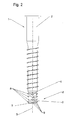
- FIG. 1 shows a foundation device 1 according to the invention, consisting on the one hand of a sleeve 2 open on both sides circular cross-section as a screw with rotating helical and on the other hand of a cup-shaped closure plug 3, which is locked with its side wall 6 in the form of a sleeve-like extension of the sleeve 2 with this and elastic deformable circumferential lamellae 8 has.
- FIG. 2 shows a foundation device 1 according to the invention, the device according to FIG. 1 is similar, but in which the threaded sleeve has a partially conical cross-section and which are formed on the closure plug 3 encircling, elastically deformable blades 8 interrupted.
- FIG. 3 shows a detail of a foundation device 1 according to the invention, consisting of a screw shown in its lower end 2 with indicated helical coil 14 and in the lower opening 4 by means of deformable Lammellen 8 guided pot-shaped closure plug 3 with side wall 6 with further elastically deformable blades 8 and a Bottom plate 7.
- FIG. 4 shows a detail of a foundation device 1 according to the invention, consisting of a sleeve 2 shown in its lower end with latched in the lower opening 4 of the sleeve 2 pot-shaped closure plug 3 with side wall 6 and radially thereabout elastically deformable fins 8 and bottom plate. 7
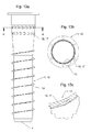
- FIG. 5a shows a cup-shaped closure plug 3 with side wall 6, radially surrounding elastically deformable blades 8 and bottom plate 7 in a perspective view.
- FIG. 5b shows the pot-shaped closure plug 3 after FIG. 5a in section
- FIG. 6a shows a cup-shaped closure plug 3 with side wall 6 with circumferential elastic lamellae 8 and bottom plate 7 and with a latching device for locking the closure plug 3 with the sleeve 2 in a perspective view.
- FIG. 6b shows the pot-shaped closure plug 3 after FIG. 6a in section.
- Figure 7a shows a cup-shaped closure plug 3 with side wall 6 with circumferential, but interrupted elastic blades 8 and bottom 7 and with a latching device for locking the closure plug 3 with the sleeve 2 in a perspective view
- FIG. 7b shows the pot-shaped closure plug 3 after Figure 7a in section.
- FIG. 8 shows a detail of a foundation device 1 according to the invention, consisting of a bottom sleeve 2 shown in its lower end as Einschraubhülse with rotating helix and end anchored cup-shaped closure plug 3 with side wall 6, elastically deformable blades 8 and bottom plate 7 with a cruciform or frustoconical cone-shaped extension 10, 11.
- FIG. 9a shows the pot-shaped closure plug 3 after FIG. 8 with means for non-rotatable anchoring to the ground socket.
- FIG. 9b shows the screw-in sleeve FIG. 8 with means for non-rotatable anchoring of the closure plug.
- FIG. 10a shows a foundation device 1 as a conical, bottom closed ringfundament 13 with helical coil 14 and a surface design in the form of a circumferential tooth-like knurling 15th
- FIG. 10b shows an enlarged section through the tooth-like knurling 15 according to FIG. 10a
- FIG. 11 shows a foundation device 1 as a cone-shaped screw foundation 13 with helical coil 14 and a surface configuration in the form of circumferentially extending scales 16th
- FIG. 12a shows a foundation device 1 as a top and bottom open SSfundament 13 with a surface configuration in the form of circumferentially extending scales 16th
- FIG. 12b shows a section through the screw foundation 13 after FIG. 12a on the line A / A
- FIG. 12c shows an enlarged detail of the section FIG. 12b .
- FIG. 13a shows a foundation device 1 as above and below open SSfundament 13 with helical coil 14 and a surface configuration in the form of circumferentially extending, undercut scales 17th
- FIG. 13b shows a section through the screw foundation 13 after FIG. 13a on the line B / B.
- FIG. 13c shows an enlarged detail of the section FIG. 13b .
- FIG. 14 shows the spatial, partially cutaway view of a foundation device 1 according to the invention after its screwing into the soil 21.
- the foundation device in the form of a sleeve-like body 2 consists of a designed as a displacement body anchoring portion 18 and a holding or plugging portion 19 of the anchoring portion 18 has a conical region 20 with helical screw 14 for screwing into the soil 21, a transition region 29 between the conical portion 20 and upper part 22 and an upper part 22 of the anchoring portion 18 and a molded or attached or plugged this holding part 19, 32 with a receptacle 34.
- Part 19, 32 shown above part can also be interpreted as inserted in a receptacle 34 of the anchoring portion 18 rod, mast, posts or the like.
- the upper part 22 of the anchoring section 18, which is arranged above the conical region 20, has, as the holding part 19, 32 attached to it, a square cross-section, therefore, as also shown on the holding part 19, 32, in at least one, in fact but in two extending through its longitudinal axis 5 cutting planes 23, namely in the diagonal, zones larger diameter 24 than the diameter 25 of the base of the conical portion 20
- By screwing the anchoring portion 18 in the soil 21 are in the range of - here in cross section square -
- Upper part 22 of the anchoring portion 18 produced by displacement generated fillable gaps 26, which are filled with filler 30.
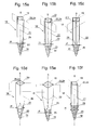
- FIGS. 15 a - f show spatial representations of various anchoring sections 18 according to the invention.
- FIG. 15 Figure a shows an anchoring portion 18 with upper portion 22 of anchoring portion 18 disposed above the conical portion 20 provided with helical coil 14 as a double edge and with a section plane 23 passing through a longitudinal axis 5 and the two edges forming a zone 24 of larger diameter than the diameter 25 of the base of the conical region 20 forms
- FIG. 15b shows an anchoring portion 18 with above the screw head 14 equipped with conical portion 20 arranged upper part 22 of the anchoring portion 18 in the form of a cylinder-like tube with four edges 27 a - d (see also FIG. 16d ), Saw-tooth-like formations in cross-section and with a cutting plane 23 extending through a longitudinal axis 5 defining one of two zones (formed by the two diagonals through the saw-toothed formations) of larger diameter 24 than the diameter 25 of the base of the conical zone 20 and a transitional zone 29 between conical portion 20 and upper part 22 of the anchoring portion 18th
- FIG. 15c shows an anchoring portion 18 with above the screw head 14 equipped with conical portion 20 arranged upper part 22 of the anchoring portion 18 as a square 27 a - d (see also FIG. 16b ) with inwardly deformed sides of the square and with a cutting plane 23 passing through a longitudinal axis 5 of the anchoring section 18 defining one of two zones (formed by the two diagonals) of larger diameter 24 than the diameter 25 of the base of the conical zone 20, and a transition region 29 between conical region 20 and upper part 22 of the anchoring section 18
- FIG. 15d shows a similar design, but without inwardly deformed sides of the square.
- FIG. 15e shows an anchoring portion 18 with above the screw head 14 equipped with conical portion 20 arranged upper part 22 of the anchoring portion 18 as a square 27 a - d (see FIG. 16b ) and with a cutting plane 23 extending through a longitudinal axis 5 defining one of two zones (formed by the two diagonals) of larger diameter 24 than the diameter of the base 25 of the conical zone 20 and a transition zone 29 between the conical zone 20 and the upper part 22 the anchoring portion 18.
- the helical coil 14 extends here into the transition region 29 between the conical region 20 and top 22 of the anchoring portion 18th
- FIG. 15f shows an anchoring portion 18 similar to that FIG. 15a in which the threads of the helical spiral 14 extend up into the transition region 29.
- FIG. 16 a - e show different cross sections through different upper parts 22 of anchoring sections 18, each with the circular indication of the envelope 33, which at the same time indicates the state of the displaced earth 21 in the region of the upper part 22 of the anchoring section 18 after screwing in the anchoring section 18.
- FIG. 16 a shows the state after screwing in an anchoring section 18 with a triangular upper part 22 of the anchoring section 18 with edge regions 27 a, b, longitudinal axis 5 and through them and by edges 27a and 27b extending, a zone 24 of larger diameter forming cutting plane 23 Shown are also formed by screwing the anchoring portion 18 in the region of its upper part 22 filler column 26th
- FIG. 16b shows the state after screwing in an anchoring portion 18 with square top 22 with edge portions 27 a - d, longitudinal axis 5 and through them and two edges 27 a and 27 c and 27 b and 27 d extending, two zones 24 of larger diameter forming cutting planes 23. Also shown are the fillable gaps 26 formed by screwing in the region of the upper part 22 of the anchoring section 18 and the filler material 30 shown here in only one gap segment.
- the representation here is chosen to be axisymmetric, so that all four edges to the same extent Ground 21 displace when screwing in the anchoring portion 18 and the same round, by the dimensions of the upper part 22 from each other largely separate fillable gaps 26 arise. It is understood that - if desired - by appropriate displacement of the longitudinal axis 5 of the anchoring part 18, the number of displacing acting edges 27 can be reduced to two or even one.
- FIG. 16c shows much the same as FIG. 16b However, the side walls of the polygon 27 are here - similar to in FIG. 15c shown - deformed inwards.
- FIG. 16d shows the state after screwing the anchoring portion 18 with upper part 22 according to FIG. 15b with sawtooth edge portions 27 a - d, longitudinal axis 5 and through them and two sawtooth edges 27 a and 27 c and 27 b and 27 d extending, two zones 24 of larger diameter forming cutting planes 23 are shown by the screwing in the area Upper part 22 of the anchoring section 18 formed fillable column 26, the representation here is also chosen axisymmetric, so that all four edges 27 a - d displace the soil 21 to the same extent and all around, by the dimensions of the upper part 22 from each other largely separate fillable gaps 26 arise , It is understood that - if desired - by appropriate displacement of the longitudinal axis 5, the number of displacing acting edges 27 can be reduced to two or even one.
- FIG. 16e finally shows the state after screwing in an anchoring portion 18 with two-edge upper part 22 according to FIG. 15a in which the helical coil 14 is guided into the upper part 22 and in the threads of the helical coils in the region of the upper part 22 - in the region in which fillable gaps 26 are formed when screwing in - passage openings 31 for the filling material 30 are formed.
- FIG. 17 shows a foundation device 1 according to a second embodiment of the invention.
- the fundamen worn according to this embodiment has analogously to FIG. 16e a triangle with a nose-like tip 27 a and another 27 b on.
- the maximum diameter of this cross-sectional profile is equal to the diameter 25, which characterizes the circular cross-section of the base of the conical displacement body This characterized by the diameter 25 maximum diameter of the displacement section encloses the Zweieckform 27 a, 27 b and leaves with respect to the envelopes the retracted areas 35, 36.
- the two retracted areas 35, 36 are separated.
- the cross section of an embodiment according to FIG. 17 can vary and be designed such that in the sense of Einckes only such a cam-shaped projection 27 a is present. Then, a single, almost completely recessed retracted area 35 would be formed. In a larger number of corners correspondingly more retracted areas 35, 36, etc. are present and form column 26 for filling between the surrounding soil 21 and the surface of the retracted upper part 22 of the foundation device first
Landscapes
- Engineering & Computer Science (AREA)
- Architecture (AREA)
- Civil Engineering (AREA)
- Structural Engineering (AREA)
- Foundations (AREA)
- Piles And Underground Anchors (AREA)
Applications Claiming Priority (3)
| Application Number | Priority Date | Filing Date | Title |
|---|---|---|---|
| DE200720004564 DE202007004564U1 (de) | 2007-03-28 | 2007-03-28 | Fundamenteinrichtung für im Erdreich zu verankernde Bauteile |
| DE200720004566 DE202007004566U1 (de) | 2007-03-28 | 2007-03-28 | Befestigungsvorrichtung zum Befestigen von Stäben, Pfosten, Masten o.dgl. im Erdreich und System hierzu |
| DE200720004565 DE202007004565U1 (de) | 2007-03-28 | 2007-03-28 | Fundamenteinrichtung zur Verankerung von Bauteilen im Erdreich |
Publications (2)
| Publication Number | Publication Date |
|---|---|
| EP1975345A2 true EP1975345A2 (fr) | 2008-10-01 |
| EP1975345A3 EP1975345A3 (fr) | 2014-05-14 |
Family
ID=39541999
Family Applications (1)
| Application Number | Title | Priority Date | Filing Date |
|---|---|---|---|
| EP08153478.6A Withdrawn EP1975345A3 (fr) | 2007-03-28 | 2008-03-28 | Dispositif de fondation pour éléments de construction devant être ancrés dans la terre |
Country Status (1)
| Country | Link |
|---|---|
| EP (1) | EP1975345A3 (fr) |
Cited By (2)
| Publication number | Priority date | Publication date | Assignee | Title |
|---|---|---|---|---|
| WO2009130625A2 (fr) | 2008-04-21 | 2009-10-29 | Vortek S.R.L. | Dispositif de fondations pour poteaux, pieux et autres objets similaires |
| CN115191266A (zh) * | 2019-11-06 | 2022-10-18 | 重庆交通大学 | 一种生物钉钉体结构 |
Citations (1)
| Publication number | Priority date | Publication date | Assignee | Title |
|---|---|---|---|---|
| DE102004059632A1 (de) | 2004-12-10 | 2006-06-14 | Krinner Innovation Gmbh | Fundamenteinrichutng für stabförmige Bauteile mit mehrfach verwendbarem Werkzeug sowie Vorrichtung zum einbringen einer derartigen Fundamenteinrichtung |
Family Cites Families (9)
| Publication number | Priority date | Publication date | Assignee | Title |
|---|---|---|---|---|
| US1791368A (en) * | 1929-02-20 | 1931-02-03 | Charles J Mullett | Anchor post |
| US3680274A (en) * | 1970-06-25 | 1972-08-01 | William H Chamberlain | Anchoring device |
| GB2140057B (en) * | 1983-03-14 | 1986-09-03 | Metpost Ltd | Post socket |
| GB2336169B (en) * | 1998-04-06 | 2002-03-06 | Michael Payne | A post / stanchion mounting device |
| DE19821227C2 (de) * | 1998-05-12 | 2000-07-13 | Max Haslinger | Verfahren zum Eintreiben eines Fundaments und Fundament |
| GB0018213D0 (en) * | 2000-07-26 | 2000-09-13 | Aronsson Gary J | Post ground support |
| DE10146140A1 (de) * | 2001-09-19 | 2003-04-03 | Krinner Innovation Gmbh | Befestigungsvorrichtung mit seitlichen Öffnungen |
| DE20220317U1 (de) * | 2001-12-12 | 2003-05-28 | Groß, Manfred, 94344 Wiesenfelden | Straßenleitpfostenfuß |
| BR8301127U (pt) * | 2003-05-08 | 2004-12-14 | Ivan Carta | Dispositivo de autogravação e ancoragem em solos para aplicações diversas |
-
2008
- 2008-03-28 EP EP08153478.6A patent/EP1975345A3/fr not_active Withdrawn
Patent Citations (1)
| Publication number | Priority date | Publication date | Assignee | Title |
|---|---|---|---|---|
| DE102004059632A1 (de) | 2004-12-10 | 2006-06-14 | Krinner Innovation Gmbh | Fundamenteinrichutng für stabförmige Bauteile mit mehrfach verwendbarem Werkzeug sowie Vorrichtung zum einbringen einer derartigen Fundamenteinrichtung |
Cited By (4)
| Publication number | Priority date | Publication date | Assignee | Title |
|---|---|---|---|---|
| WO2009130625A2 (fr) | 2008-04-21 | 2009-10-29 | Vortek S.R.L. | Dispositif de fondations pour poteaux, pieux et autres objets similaires |
| WO2009130625A3 (fr) * | 2008-04-21 | 2010-07-15 | Vortek S.R.L. | Dispositif de fondations pour poteaux, pieux et autres objets similaires |
| CN115191266A (zh) * | 2019-11-06 | 2022-10-18 | 重庆交通大学 | 一种生物钉钉体结构 |
| CN115191266B (zh) * | 2019-11-06 | 2024-01-23 | 重庆交通大学 | 一种生物钉钉体结构 |
Also Published As
| Publication number | Publication date |
|---|---|
| EP1975345A3 (fr) | 2014-05-14 |
Similar Documents
| Publication | Publication Date | Title |
|---|---|---|
| EP2171179B1 (fr) | Fondation forée | |
| WO1987002734A1 (fr) | Dispositif de fixation d'objets en forme de barres, en particulier des poteaux, dans le sol | |
| CH631521A5 (de) | Verankerungsbuchse. | |
| EP0080143A1 (fr) | Fondement pour un poteau, un pilier de soutien ou similaires | |
| EP2003270B1 (fr) | Système et procédé de fixation d'un objet en forme de mât ou de poteau dans le sol en terre avec une partie réceptrice en plusieurs pièces pouvant être vissées sur le sol en terre | |
| EP0590367A1 (fr) | Encrage pour être fixé dans le sol | |
| DE102007001833B4 (de) | System zur Verankerung eines Mastes, Pfostens oder dergleichen im Erdreich und Verwendung einer Befestigungsvorrichtung und eines Mastes, Pfostens oder dergleichen in einem solchen System | |
| DE4002830C2 (fr) | ||
| DE69032252T2 (de) | Verankerung und befestigungsverfahren durch in den boden getriebene seitenstützen | |
| DE60117176T2 (de) | Schutzbarriere, insbesondere im gebirge | |
| EP3190244A1 (fr) | Douille filetée d'ancrage d'éléments de construction dans un ouvrage en béton et entretoise tubulaire | |
| DE102005045574A1 (de) | Drehfundament zur Verankerung im Erdboden | |
| DE3502607A1 (de) | Anker, insbesondere lastabhaengiger duebel | |
| EP2957675A1 (fr) | Ancrage destinée à fixer des objets en forme de tige, en particulier des poteaux dans une zone urbaine (environnement) et procédé et outil pour poser l'ancrage dans la terre | |
| WO2007036263A1 (fr) | Element de fondation visse a ancrer dans le sol | |
| DE202011052381U1 (de) | Pfostenträger | |
| DE202007004564U1 (de) | Fundamenteinrichtung für im Erdreich zu verankernde Bauteile | |
| EP0542692B1 (fr) | Dispositif pour l'ancrage d'éléments de construction dans le sol | |
| DE202007004565U1 (de) | Fundamenteinrichtung zur Verankerung von Bauteilen im Erdreich | |
| DE102021134573A1 (de) | Befestigungselement, insbesondere für Solarpanele | |
| EP2497879B1 (fr) | Fixation d'une plaque de monument sur une fondation | |
| DE102008015780A1 (de) | Mechanische Sperrvorrichtung | |
| DE202007004566U1 (de) | Befestigungsvorrichtung zum Befestigen von Stäben, Pfosten, Masten o.dgl. im Erdreich und System hierzu | |
| CH700761A2 (de) | Bodenhülse und Pfosten einer Hochwasserschutzanlage sowie Hochwasserschutzanlage umfassend Bodenhülsen und Pfosten. | |
| DE9409252U1 (de) | Bodenverankerung für Pfähle, insbesondere Zaunpfähle |
Legal Events
| Date | Code | Title | Description |
|---|---|---|---|
| PUAI | Public reference made under article 153(3) epc to a published international application that has entered the european phase |
Free format text: ORIGINAL CODE: 0009012 |
|
| 17P | Request for examination filed |
Effective date: 20080328 |
|
| AK | Designated contracting states |
Kind code of ref document: A2 Designated state(s): AT BE BG CH CY CZ DE DK EE ES FI FR GB GR HR HU IE IS IT LI LT LU LV MC MT NL NO PL PT RO SE SI SK TR |
|
| AX | Request for extension of the european patent |
Extension state: AL BA MK RS |
|
| RIC1 | Information provided on ipc code assigned before grant |
Ipc: E04H 12/22 20060101AFI20131108BHEP |
|
| PUAL | Search report despatched |
Free format text: ORIGINAL CODE: 0009013 |
|
| AK | Designated contracting states |
Kind code of ref document: A3 Designated state(s): AT BE BG CH CY CZ DE DK EE ES FI FR GB GR HR HU IE IS IT LI LT LU LV MC MT NL NO PL PT RO SE SI SK TR |
|
| AX | Request for extension of the european patent |
Extension state: AL BA MK RS |
|
| RIC1 | Information provided on ipc code assigned before grant |
Ipc: E04H 12/22 20060101AFI20140407BHEP |
|
| AKX | Designation fees paid |
Designated state(s): AT BE BG CH CY CZ DE DK EE ES FI FR GB GR HR HU IE IS IT LI LT LU LV MC MT NL NO PL PT RO SE SI SK TR |
|
| AXX | Extension fees paid |
Extension state: BA Extension state: RS Extension state: MK Extension state: AL |
|
| STAA | Information on the status of an ep patent application or granted ep patent |
Free format text: STATUS: THE APPLICATION IS DEEMED TO BE WITHDRAWN |
|
| 18D | Application deemed to be withdrawn |
Effective date: 20141115 |