EP1975355A2 - Complément d'équipement pour une porte coulissante et installation de porte coulissante - Google Patents
Complément d'équipement pour une porte coulissante et installation de porte coulissante Download PDFInfo
- Publication number
- EP1975355A2 EP1975355A2 EP07023738A EP07023738A EP1975355A2 EP 1975355 A2 EP1975355 A2 EP 1975355A2 EP 07023738 A EP07023738 A EP 07023738A EP 07023738 A EP07023738 A EP 07023738A EP 1975355 A2 EP1975355 A2 EP 1975355A2
- Authority
- EP
- European Patent Office
- Prior art keywords
- sliding door
- profile
- retrofit kit
- kit according
- suspension
- Prior art date
- Legal status (The legal status is an assumption and is not a legal conclusion. Google has not performed a legal analysis and makes no representation as to the accuracy of the status listed.)
- Granted
Links
Images







Classifications
-
- E—FIXED CONSTRUCTIONS
- E05—LOCKS; KEYS; WINDOW OR DOOR FITTINGS; SAFES
- E05F—DEVICES FOR MOVING WINGS INTO OPEN OR CLOSED POSITION; CHECKS FOR WINGS; WING FITTINGS NOT OTHERWISE PROVIDED FOR, CONCERNED WITH THE FUNCTIONING OF THE WING
- E05F15/00—Power-operated mechanisms for wings
- E05F15/60—Power-operated mechanisms for wings using electrical actuators
- E05F15/603—Power-operated mechanisms for wings using electrical actuators using rotary electromotors
- E05F15/632—Power-operated mechanisms for wings using electrical actuators using rotary electromotors for horizontally-sliding wings
- E05F15/643—Power-operated mechanisms for wings using electrical actuators using rotary electromotors for horizontally-sliding wings operated by flexible elongated pulling elements, e.g. belts, chains or cables
-
- E—FIXED CONSTRUCTIONS
- E05—LOCKS; KEYS; WINDOW OR DOOR FITTINGS; SAFES
- E05D—HINGES OR SUSPENSION DEVICES FOR DOORS, WINDOWS OR WINGS
- E05D15/00—Suspension arrangements for wings
- E05D15/06—Suspension arrangements for wings for wings sliding horizontally more or less in their own plane
- E05D15/0621—Details, e.g. suspension or supporting guides
- E05D15/0626—Details, e.g. suspension or supporting guides for wings suspended at the top
- E05D15/0652—Tracks
-
- E—FIXED CONSTRUCTIONS
- E05—LOCKS; KEYS; WINDOW OR DOOR FITTINGS; SAFES
- E05F—DEVICES FOR MOVING WINGS INTO OPEN OR CLOSED POSITION; CHECKS FOR WINGS; WING FITTINGS NOT OTHERWISE PROVIDED FOR, CONCERNED WITH THE FUNCTIONING OF THE WING
- E05F15/00—Power-operated mechanisms for wings
- E05F15/60—Power-operated mechanisms for wings using electrical actuators
-
- E—FIXED CONSTRUCTIONS
- E05—LOCKS; KEYS; WINDOW OR DOOR FITTINGS; SAFES
- E05F—DEVICES FOR MOVING WINGS INTO OPEN OR CLOSED POSITION; CHECKS FOR WINGS; WING FITTINGS NOT OTHERWISE PROVIDED FOR, CONCERNED WITH THE FUNCTIONING OF THE WING
- E05F15/00—Power-operated mechanisms for wings
- E05F15/60—Power-operated mechanisms for wings using electrical actuators
- E05F15/603—Power-operated mechanisms for wings using electrical actuators using rotary electromotors
- E05F15/632—Power-operated mechanisms for wings using electrical actuators using rotary electromotors for horizontally-sliding wings
-
- E—FIXED CONSTRUCTIONS
- E05—LOCKS; KEYS; WINDOW OR DOOR FITTINGS; SAFES
- E05F—DEVICES FOR MOVING WINGS INTO OPEN OR CLOSED POSITION; CHECKS FOR WINGS; WING FITTINGS NOT OTHERWISE PROVIDED FOR, CONCERNED WITH THE FUNCTIONING OF THE WING
- E05F15/00—Power-operated mechanisms for wings
- E05F15/60—Power-operated mechanisms for wings using electrical actuators
- E05F15/603—Power-operated mechanisms for wings using electrical actuators using rotary electromotors
- E05F15/632—Power-operated mechanisms for wings using electrical actuators using rotary electromotors for horizontally-sliding wings
- E05F15/635—Power-operated mechanisms for wings using electrical actuators using rotary electromotors for horizontally-sliding wings operated by push-pull mechanisms, e.g. flexible or rigid rack-and-pinion arrangements
-
- E—FIXED CONSTRUCTIONS
- E05—LOCKS; KEYS; WINDOW OR DOOR FITTINGS; SAFES
- E05Y—INDEXING SCHEME ASSOCIATED WITH SUBCLASSES E05D AND E05F, RELATING TO CONSTRUCTION ELEMENTS, ELECTRIC CONTROL, POWER SUPPLY, POWER SIGNAL OR TRANSMISSION, USER INTERFACES, MOUNTING OR COUPLING, DETAILS, ACCESSORIES, AUXILIARY OPERATIONS NOT OTHERWISE PROVIDED FOR, APPLICATION THEREOF
- E05Y2201/00—Constructional elements; Accessories therefor
- E05Y2201/10—Covers; Housings
-
- E—FIXED CONSTRUCTIONS
- E05—LOCKS; KEYS; WINDOW OR DOOR FITTINGS; SAFES
- E05Y—INDEXING SCHEME ASSOCIATED WITH SUBCLASSES E05D AND E05F, RELATING TO CONSTRUCTION ELEMENTS, ELECTRIC CONTROL, POWER SUPPLY, POWER SIGNAL OR TRANSMISSION, USER INTERFACES, MOUNTING OR COUPLING, DETAILS, ACCESSORIES, AUXILIARY OPERATIONS NOT OTHERWISE PROVIDED FOR, APPLICATION THEREOF
- E05Y2201/00—Constructional elements; Accessories therefor
- E05Y2201/10—Covers; Housings
- E05Y2201/11—Covers
-
- E—FIXED CONSTRUCTIONS
- E05—LOCKS; KEYS; WINDOW OR DOOR FITTINGS; SAFES
- E05Y—INDEXING SCHEME ASSOCIATED WITH SUBCLASSES E05D AND E05F, RELATING TO CONSTRUCTION ELEMENTS, ELECTRIC CONTROL, POWER SUPPLY, POWER SIGNAL OR TRANSMISSION, USER INTERFACES, MOUNTING OR COUPLING, DETAILS, ACCESSORIES, AUXILIARY OPERATIONS NOT OTHERWISE PROVIDED FOR, APPLICATION THEREOF
- E05Y2201/00—Constructional elements; Accessories therefor
- E05Y2201/40—Motors; Magnets; Springs; Weights; Accessories therefor
- E05Y2201/46—Magnets
-
- E—FIXED CONSTRUCTIONS
- E05—LOCKS; KEYS; WINDOW OR DOOR FITTINGS; SAFES
- E05Y—INDEXING SCHEME ASSOCIATED WITH SUBCLASSES E05D AND E05F, RELATING TO CONSTRUCTION ELEMENTS, ELECTRIC CONTROL, POWER SUPPLY, POWER SIGNAL OR TRANSMISSION, USER INTERFACES, MOUNTING OR COUPLING, DETAILS, ACCESSORIES, AUXILIARY OPERATIONS NOT OTHERWISE PROVIDED FOR, APPLICATION THEREOF
- E05Y2201/00—Constructional elements; Accessories therefor
- E05Y2201/60—Suspension or transmission members; Accessories therefor
- E05Y2201/622—Suspension or transmission members elements
- E05Y2201/658—Members cooperating with flexible elongated pulling elements
- E05Y2201/672—Tensioners, tension sensors
-
- E—FIXED CONSTRUCTIONS
- E05—LOCKS; KEYS; WINDOW OR DOOR FITTINGS; SAFES
- E05Y—INDEXING SCHEME ASSOCIATED WITH SUBCLASSES E05D AND E05F, RELATING TO CONSTRUCTION ELEMENTS, ELECTRIC CONTROL, POWER SUPPLY, POWER SIGNAL OR TRANSMISSION, USER INTERFACES, MOUNTING OR COUPLING, DETAILS, ACCESSORIES, AUXILIARY OPERATIONS NOT OTHERWISE PROVIDED FOR, APPLICATION THEREOF
- E05Y2600/00—Mounting or coupling arrangements for elements provided for in this subclass
- E05Y2600/40—Mounting location; Visibility of the elements
- E05Y2600/46—Mounting location; Visibility of the elements in or on the wing
-
- E—FIXED CONSTRUCTIONS
- E05—LOCKS; KEYS; WINDOW OR DOOR FITTINGS; SAFES
- E05Y—INDEXING SCHEME ASSOCIATED WITH SUBCLASSES E05D AND E05F, RELATING TO CONSTRUCTION ELEMENTS, ELECTRIC CONTROL, POWER SUPPLY, POWER SIGNAL OR TRANSMISSION, USER INTERFACES, MOUNTING OR COUPLING, DETAILS, ACCESSORIES, AUXILIARY OPERATIONS NOT OTHERWISE PROVIDED FOR, APPLICATION THEREOF
- E05Y2600/00—Mounting or coupling arrangements for elements provided for in this subclass
- E05Y2600/50—Mounting methods; Positioning
- E05Y2600/52—Toolless
-
- E—FIXED CONSTRUCTIONS
- E05—LOCKS; KEYS; WINDOW OR DOOR FITTINGS; SAFES
- E05Y—INDEXING SCHEME ASSOCIATED WITH SUBCLASSES E05D AND E05F, RELATING TO CONSTRUCTION ELEMENTS, ELECTRIC CONTROL, POWER SUPPLY, POWER SIGNAL OR TRANSMISSION, USER INTERFACES, MOUNTING OR COUPLING, DETAILS, ACCESSORIES, AUXILIARY OPERATIONS NOT OTHERWISE PROVIDED FOR, APPLICATION THEREOF
- E05Y2600/00—Mounting or coupling arrangements for elements provided for in this subclass
- E05Y2600/60—Mounting or coupling members; Accessories therefor
- E05Y2600/626—Plates or brackets
-
- E—FIXED CONSTRUCTIONS
- E05—LOCKS; KEYS; WINDOW OR DOOR FITTINGS; SAFES
- E05Y—INDEXING SCHEME ASSOCIATED WITH SUBCLASSES E05D AND E05F, RELATING TO CONSTRUCTION ELEMENTS, ELECTRIC CONTROL, POWER SUPPLY, POWER SIGNAL OR TRANSMISSION, USER INTERFACES, MOUNTING OR COUPLING, DETAILS, ACCESSORIES, AUXILIARY OPERATIONS NOT OTHERWISE PROVIDED FOR, APPLICATION THEREOF
- E05Y2800/00—Details, accessories and auxiliary operations not otherwise provided for
-
- E—FIXED CONSTRUCTIONS
- E05—LOCKS; KEYS; WINDOW OR DOOR FITTINGS; SAFES
- E05Y—INDEXING SCHEME ASSOCIATED WITH SUBCLASSES E05D AND E05F, RELATING TO CONSTRUCTION ELEMENTS, ELECTRIC CONTROL, POWER SUPPLY, POWER SIGNAL OR TRANSMISSION, USER INTERFACES, MOUNTING OR COUPLING, DETAILS, ACCESSORIES, AUXILIARY OPERATIONS NOT OTHERWISE PROVIDED FOR, APPLICATION THEREOF
- E05Y2800/00—Details, accessories and auxiliary operations not otherwise provided for
- E05Y2800/20—Combinations of elements
- E05Y2800/23—Combinations of elements of elements of different categories
- E05Y2800/232—Combinations of elements of elements of different categories of motors and transmissions
-
- E—FIXED CONSTRUCTIONS
- E05—LOCKS; KEYS; WINDOW OR DOOR FITTINGS; SAFES
- E05Y—INDEXING SCHEME ASSOCIATED WITH SUBCLASSES E05D AND E05F, RELATING TO CONSTRUCTION ELEMENTS, ELECTRIC CONTROL, POWER SUPPLY, POWER SIGNAL OR TRANSMISSION, USER INTERFACES, MOUNTING OR COUPLING, DETAILS, ACCESSORIES, AUXILIARY OPERATIONS NOT OTHERWISE PROVIDED FOR, APPLICATION THEREOF
- E05Y2800/00—Details, accessories and auxiliary operations not otherwise provided for
- E05Y2800/70—Retrofitting of elements
-
- E—FIXED CONSTRUCTIONS
- E05—LOCKS; KEYS; WINDOW OR DOOR FITTINGS; SAFES
- E05Y—INDEXING SCHEME ASSOCIATED WITH SUBCLASSES E05D AND E05F, RELATING TO CONSTRUCTION ELEMENTS, ELECTRIC CONTROL, POWER SUPPLY, POWER SIGNAL OR TRANSMISSION, USER INTERFACES, MOUNTING OR COUPLING, DETAILS, ACCESSORIES, AUXILIARY OPERATIONS NOT OTHERWISE PROVIDED FOR, APPLICATION THEREOF
- E05Y2900/00—Application of doors, windows, wings or fittings thereof
- E05Y2900/10—Application of doors, windows, wings or fittings thereof for buildings or parts thereof
- E05Y2900/13—Type of wing
- E05Y2900/132—Doors
Definitions
- the invention relates to a retrofit kit for a sliding door and a sliding door system.
- the sliding door system is based on a belt drive.
- An endless belt is guided around two pulleys.
- the endless belt is operatively connected via a driver with one of the sliding doors.
- a drive unit is provided, which has an outwardly projecting output shaft.
- the output shaft and one of the pulleys are designed so that the output shaft when attaching the drive unit to this pulley with her in rotational engagement.
- the drive unit is not in single-leaf sliding door systems and sliding door systems that do not have a pulley, usable.
- a sliding door system in which a sliding door can be provided with a drive.
- the drive is based on a friction mechanism.
- the sliding door has a friction surface on an upper edge for this purpose.
- a drive rail is provided above the sliding door, which has a friction surface.
- the sliding door is connected to each other stationary with the drive rail.
- the sliding door or the drive rail with the friction surface is arranged below a ceiling rail. In the case of a drive rail, this is attached to the ceiling rail.
- Friction wheels are arranged pressing against the respective friction surface. The pressure effect can be achieved by means of preloaded springs.
- the drive motor for the friction wheels is also attached to the ceiling rail and drives the friction wheels pressing against the sliding door.
- the drive motor is arranged outside a suspension for the sliding door, ie in front of or behind the suspension, with respect to a walking direction.
- This type of drives is not suitable for sliding door systems that are not mounted on a ceiling but on a building wall.
- the sliding doors are to be provided with a friction surface or to attach a drive rail to the respective sliding door.
- the object of the invention is therefore to provide a universal drive, by means of which in particular manually operated sliding doors of almost any kind can be retrofitted cost and easily with a motor drive.
- the object is achieved by means of a retrofit kit for at least one sliding door.
- a retrofit kit for at least one sliding door When retrofitting the at least one sliding door of the retrofit kit is attached to a suspension of the sliding door.
- the sliding door is mounted rolling on a guide rail of this suspension by means of single rollers or carriages. Alternatively, the sliding door can also be suspended and guided by means of magnetic force.
- the retrofit kit also has a suspension.
- a drive for the sliding door is added.
- retrofitting the drive is connected to a holder of a single role, with a carriage, with a driver or with the at least one sliding door itself.
- the holder, the carriage or the driver are each operatively connected to the at least one sliding door.
- the sliding doors are typically operatively connected to one another via one or more traction means.
- the sliding doors are operatively connected by means of a driver with the one or more traction means.
- this type of sliding door systems according to the invention alternatively provided to connect the drive with one of the drivers in the manner described.
- the invention provides for the drive to be effectively connected to the sliding door itself.
- This offers an even higher versatility, since also sliding door systems can be retrofitted, where there are no single rollers or carriages. This is the case, for example, with purely magnetically held sliding doors.
- An inventive retrofit kit preferably has a profile which is adapted to receive the necessary parts for driving a sliding door.
- the profile can be fixedly attached to an already existing profile of a suspension of the sliding door to be automated. This ensures that in a sliding door system, where the each sliding door is attached, as many parts of the suspension continue to be used as possible, which helps to reduce the cost of retrofitting.
- the attachment of the profile according to the invention is preferably carried out by means of a screw fastening.
- a mounting plate for example by means of a screw to the existing profile of the sliding door system.
- the inventive profile including drive is then hung instead of the profile of the suspension of the sliding door in the mounting plate or inserted and locked to it.
- the locking can be done by means of turn a now accessible screw or by means of a locking mechanism 'preferably by means of Einklipsens. This has the advantage that the profile with inserted drive is possible even if the otherwise provided fastening screws for the profile are difficult to access.
- the profile according to the invention is designed in a region for a suspension of the respective sliding door; it is shaped in the area as the existing profile of the sliding door system. In a region other than the area for the suspension of the sliding door, the profile for receiving a drive is formed.
- the advantage is that apart from the existing profile of the sliding door suspension, all other parts of the existing sliding door system continue to be used. Furthermore, the existing mounting options are used; new ones are not required. This facilitates retrofitting. There must be no holes with a prescribed accuracy drilled into the profile of the suspension and possibly threaded into it, which simplifies assembly.
- the drive is coupled according to the invention with a driver part, which is the connection to the suspension of the sliding door, d. H. to a single roll holder, a carriage, a driver or the sliding door itself, manufactures.
- the driver part may be part of the drive or be formed separately.
- a cover is additionally providable, which is preferably clipped to the profile according to the invention and the profile down and forward and to the sides, d. H. away from the sliding door and thus visually obscured to the outside.
- a protection against contamination may be provided, as it is also used in conventional sliding door systems.
- this protection is effected by means of a brush arrangement which is attached to the cover and is arranged in the direction of the sliding door.
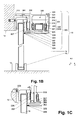
- the sliding door system 10 essentially comprises a suspension 200, on which at least one sliding door 11 is suspended.
- the suspension 200 preferably has a base profile 201, which by means of a fastening screw 203 when in FIG. 1 example shown attached to a wall 12.
- a profile 202 is fixed in place.
- the profile 202 has a roller section or a guide rail 208, on which the rollers 207 roll.
- the rollers 207 may be attached by means of a mounting stop or a holder on the sliding door 11. But you can also, as in FIG. 1 shown to be integrated in a carriage 206, which in turn is fixedly mounted on the sliding door 11. Furthermore, the Profile 202, a brush holder 209, are received in the brush 204. The free ends of the brushes 204, ie the ends of the brushes 204 facing away from the brush holder 209, point in the direction of the sliding door 11 and rest on it. This provides effective protection against pollution. In a bottom region 14, the sliding door 11 is received in a guide 15, whereby a tilting out of the sliding door 11 from the sliding door suspension 200 is prevented.
- a suspension 300 according to a first embodiment of the invention, as in FIG. 1B shown, provided.
- the suspension 300 has a profile 301.
- the profile 202 according to Figure 1A replaced with the profile 301.
- the profile 301 preferably has an intermediate wall section 318.
- the intermediate wall portion 318 divides the profile 301 into two areas.
- FIG. 1B To the left of the intermediate wall portion 318 lying portion of the profile 301 is like that in Figure 1A formed profile 202 and thus configured to perform the same functions as the profile 202.
- the profile 301 analogous to the profile 202 a roller portion or a guide rail 317, are mounted on the rollers 207 of sliding doors 11 rolling.
- FIG. 1B To the right of the intermediate wall section 318 lying portion of the profile 301 serves to accommodate all parts of a drive 303, ie all parts that are required to move the sliding door 11. For this purpose is between the intermediate wall portion 318 and a parallel to him, in the z-coordinate direction in FIG. 1B arranged at a predetermined distance Sidewall portion 319 created a receiving portion 328 in the form of a cavity.
- the intermediate wall section 318, the side wall section 319 and optionally an upper wall section connecting the two wall sections are correspondingly shaped towards the cavity for receiving the parts of the drive 303. Ie. the parts of a drive 300 are held by means of inside wall sections of the receiving section 328.
- the drive 303 is formed as a linear drive by means of a linear motor.
- the linear motor comprises a rotor 320, which preferably consists of a magnetizable or magnetic material and is stored guided by means of rotor rollers 322 guided in the profile 301.
- the linear motor further comprises a stator, not shown, which preferably consists of an arrangement of electric coils.
- the stator preferably extends over an entire travel length of the sliding door 11 to be moved and is arranged in the profile 301 above the rotor 320.
- the sliding door 11 moves by means of the drive 303, d. H. can be moved, a driver part 304 is attached to a bottom of the rotor 320.
- the driver part 304 is part of the rotor 320 itself and is itself moved due to an alternating magnetic field generated in the stator.
- the driver part 304 is arranged so that it is substantially horizontally from the rotor 320, ie in the -z coordinate direction in FIG. 1B extending to the sliding door 11.
- the driver member 304 thereby undermines the intermediate wall portion 318 of the profile 301.
- D. h. the driver part 304 extends below the intermediate wall section 318 and has at least in the region which is below the intermediate wall section 318 is in the y-coordinate direction to this a predetermined, preferably slight distance.
- the driver part 304 has at one end, which faces the sliding door 11, a driver portion 305.
- the driver portion 305 stands, as in FIG. 1B indicated, with a carriage 206 in operative connection.
- a movement of the driver part 304 in at least one travel direction ⁇ x causes a movement of the sliding door 11 in the same direction.
- the side wall portion 319 is outside, d. H. in the z-coordinate direction and / or in the -y coordinate direction, preferably designed so that a cover 302 can be attached.
- the side wall section 319 preferably has latch receptacles 323 or latching sections 324, preferably in the form of latching projections.
- the cover 302 has at the locations opposite the latching receptacles 323 or locking portions 324, latching portions 324 and latching receptacles 323, so that the cover 302 can be clipped onto the profile 301 and also easily removed again.
- the arrangement of locking receptacles 323 and latching portions 324 leads to a locking of the cover 302 in the clip-in state.
- the latching sections 323 and latching receptacles 324 can also be designed as holding projections.
- the cover 302 is preferably designed to optically conceal not only the profile 301 in the z-coordinate direction but also the cam member 304 in the -y coordinate direction and preferably also towards the sides in the ⁇ x coordinate direction. As a result, the parts of the suspension 300 are no longer visible from the outside.
- the cover 302 extends as in FIG FIG. 1B shown in the attachment state preferably from an upper edge of the profile 301 along the side wall 319, "kinks" below the side wall portion 319 in the direction Sliding door 11 and then preferably extends to a sliding door 11 out that the sliding door 11 facing the end of the cover 302 to the sliding door 11 has a predetermined, preferably small distance.
- the cover 302 preferably has a brush arrangement similar to that in FIG Figure 1A shown suspension 200 is provided.
- a brush receptacle 325 extending in the x-coordinate direction is formed, which is open towards the sliding door 11.
- Brushes 326 are received in brush receptacle 325 so that they extend in the direction of sliding door 11. The free ends of the brushes 326 abut the sliding door 11, thus providing protection against contamination.
- a foam insert can be used instead of the brushes 326.
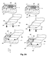
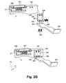
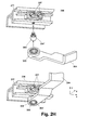
- FIGS. 2A to 2J Different versions of active connections between driver part 304 and carriage 206 are shown.
- FIG. 2A a sliding door carriage 206 is shown in a perspective view.
- the carriage 206 preferably has a device for clamping with a sliding door 11 and a height adjustment. Further, the carriage 206 on rollers 207, which on the in FIG. 1B shown guide rail 317 of the profile 301 are freely rotatable and guided.
- the carriage 206 preferably has a in x coordinate direction seen substantially C-shaped profile 211 on.
- FIG. 2A further shows an operative connection between driver part 304 and carriage 206 according to a first embodiment of the invention.
- threaded holes 307 are formed extending in the y-coordinate direction.
- the driver member 304 in the y-coordinate direction extending through holes 308, the number of which is equal to the number of threaded holes 307.
- the through holes are formed so as to be aligned with the tapped holes 307 in a state where the profile 301 including the driver 303 and the dog member 304 is mounted.
- fastening screws 306 are screwed through the through openings 308 into the threaded bores.
- spacers are preferably arranged in the form of spacers 327, which bridge this distance.
- the spacers may be integrally formed with the driver part 304.
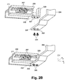
- FIG. 2B shows an operative connection between driver part 304 and carriage 206 according to a second embodiment of the invention.
- one of the side surfaces of the carriage 206 which is in the z-coordinate direction is preferably used as a stop surface.
- the operative connection comprises a stop part 329.
- the stop part 329 has a fastening section 332 in a region facing the driver part 304.
- threaded bores 307 are formed extending in the y-coordinate direction.
- the driver portion 305 of the driver 304 304 extending through openings 308 are formed in the y-coordinate direction. From a side facing away from the mounting portion 332 of the driver portion 305 forth fastening screws 306 are screwed through the through holes 308 passing into the threaded holes 307.
- the abutment part 329 strikes against the carriage 206 during a movement in the -x coordinate direction and takes it along. Ie. the stop member 329 comes to lie on actuation of the drive 303 on the side surface of the profile 211, which is remote from the drive direction of the drive 303. The stop member 329 thus pushes the carriage 206 in the drive direction, in FIG. 2B case shown in -x coordinate direction.
- This embodiment is particularly suitable for sliding door systems that already have a mechanical, mostly spring-based sliding door opening system or sliding door locking system.
- a force directed against a drive direction of the drive 303 is exerted on the carriage 206.
- the stop member 329 is always on the carriage 206. An impact and related shocks and possible damage are thus avoided.
- this embodiment can be used in particular in cases where the carriage 206 in the Area in which the stop member 329 strike, made of magnetizable material.
- the stop member 329 is made in the case of magnetic material, so it is constantly on the carriage 206 at. As a result, striking and related shocks and possible damage are avoided.
- the drive 301 can drive the sliding door or doors 11 in both directions of travel.
- the stop member 329 is preferably formed by means of a high-performance magnet, preferably rare-earth high-performance magnet.
- the rare earth high performance magnet is preferably made of neodymium-iron-boron (NeFeB) or samarium-cobalt (Sm 2 Co) or plastic-bonded magnet materials.
- An advantage of the second embodiment over the first embodiment is that no machining is necessary on the carriage 206, which simplifies the retrofitting and eliminates possible sources of error during assembly.
- the stop member 329 has a receiving space 331, which is preferably complementary to the shape of the part of the carriage 206, which is to be received by the stop member 329 and to be encompassed therewith.
- the receiving space 331 is formed by means of a profile which is substantially U-shaped in cross section in the z-coordinate direction.
- the U is designed to be open in the direction of carriage 206.
- the stop member 329 is pushed from below onto the carriage 206, wherein the two, in the y-coordinate direction extending side legs engage around the carriage 206.
- the legs preferably have a distance from each other which is substantially equal to a dimension of the carriage 206 in the x-coordinate direction.
- the stop member 329 has horizontally, d. H. Parallel to an x-z plane seen on a bottom threaded holes 307 extending in the y-coordinate direction.
- the driver section 305 of the driver part 304 has correspondingly formed through openings 308. By means of fastening screws 306 driver part 304 and stop member 329 are fastened together.
- This embodiment may be modified such that the U is not open in the y-coordinate direction upwards but in -z-coordinate direction in the direction of the sliding door 11. Ie. In this case, the stopper part is pushed from the drive view from the front. This is particularly suitable for an operative connection with a driver of a multi-leaf sliding door system 10.
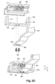
- a fourth embodiment of the invention is provided, the driver part 304 and the carriage 206, as in FIG. 2D shown with to provide a Velcro connection 309.
- a hook tape or a mushroom tape is preferably attached by gluing.
- a fleece band, a suede band or a mushroom band is likewise adhesively attached to the upper side of the driver portion 305 or to the underside of the carriage 206.
- An in the first embodiment with respect to FIG. 2A described distance between the underside of the carriage 206 and driver portion 305 is preferably bridged by the fact that the driver portion 305 in the direction of the carriage 206 toward a larger extent has, that is made thicker.
- the fourth embodiment is particularly suitable for sliding door systems 10, in which no great effort for driving the respective sliding door 11 is required. This is the case, for example, with lightweight sliding doors 11.
- a stop member 329 as in Figure 2E shown horizontally in the x-coordinate direction, preferably formed as a profile with the shape of an inverted U.
- the legs of the U-shaped profile extend with their free ends in the direction of the sliding door eleventh
- the stop member 329 preferably has a length which is equal to the distance between two immediately adjacent carriages 206, on which one and the same sliding door 11 is suspended. The stop member 329 thus abuts the mutually facing side surfaces of these two carriages 206 and can safely take the sliding door 11.
- the distance between the free ends of the legs of the abutment part 329 is preferably a little smaller than a depth dimension of the sliding door 11 in this area, i. H. whose dimensions are horizontal, d. H. in an x-z plane, in the z-coordinate direction.
- a depth dimension of the sliding door 11 in this area i. H. whose dimensions are horizontal, d. H. in an x-z plane, in the z-coordinate direction.
- the clamping force of the stop member 329 may be so large that it alone is sufficient that the stop member 329 can take the sliding door. In that case, the length of the abutment part 329 may be less than the distance between the two immediately adjacent carriages 206 on which one and the same sliding door 11 is suspended.
- a clamping device may be provided on the stop member 329, as they are used, for example, in suspension devices in which, for example, frameless glass sliding doors are hung without mounting holes.
- the abutment part 329 On a side surface of the abutment part 329 facing the drive 303, the abutment part 329 has a preferably centrally arranged attachment section 332.
- the fastening section 332 preferably has an L-shaped cross-sectional shape, viewed horizontally in the x-coordinate direction, that is to say L points in the direction of the drive 303, ie in the z-coordinate direction.
- threaded holes 307 are formed on an underside of the attachment portion 332 extending in the y-coordinate direction.
- the driver portion 305 of the driver 304 has passage openings 308, which are formed analogously to the embodiments already described.
- Driver member 304 and mounting portion 332 are secured together by means of fastening screws 306.
- the stopper member 329 is preferably formed as in FIG Figure 2F shown.
- the stop member 329 has two attachment portions 330, 332.
- the attachment portion 330 is formed so that it preferably rests on the top of a sliding door 11 in an area where there is no carriage 206 and a roller 207, respectively.
- threaded bores 307 are formed, which are arranged so that in each case a through hole 308 is aligned with a threaded bore 307. From the top of the mounting portion 330 in FIG Figure 2F Fastening screws 306 are screwed through the passage openings 308 into the threaded bores 307.
- the fixing portion 332 is formed to be in accordance with Figure 2F preferably rests on the top of a driver portion 305 of the driver 304.
- two threaded bores 307 are preferably provided, which extend in the direction of the driver part 304.
- the driver portion 305 has through holes 308, which are arranged so that in each case a through hole 308 is aligned with a threaded bore 307. From the underside of the driver 305 in Figure 2F Fastening screws 306 are screwed through the passage openings 308 into the threaded bores 307.
- an operative connection according to a seventh embodiment of the invention differs from the described sixth embodiment in the design and attachment of the abutment member 329 to a sliding door 11.
- the stop member 329 has a mounting portion 332, which is formed as in the operative connection according to the sixth embodiment of the invention.
- the stopper member 329 has a fixing portion 330 which is formed so that the stopper member 329 in -z coordinate direction can be fastened to a sliding door 11.
- at least two threaded holes 307 are formed in the sliding door 11, which in z coordinate direction in FIG. 2G extend.
- passage openings 308 are formed in the attachment portion 330. From the front of the attachment portion 333 in FIG. 2G Fastening screws 306 are screwed through the passage openings 308 into the threaded bores 307.
- the stop member 329 and the driver member 304 may also be integrally formed. In that case, the respective threaded holes 307, through holes 308 and fixing screws 306 are omitted.
- the driver portion 305 of the driver 304 has an insertion, which preferably by means of a in FIG. 2H hatched represented, elastically deformable insert is provided.
- a second driver part 304 ' is provided which is fixedly attached to a respective carriage 206, for example by means of screwing.
- a non-circular outer contour preferably in the form of an external hexagon.
- the second driver part 304 ' is first screwed into the carriage 206.
- the driver member 304 is fitted with the driver portion 305 on a driver portion 305 'of the driver 304', whereby both driver parts 304, 304 'engage with each other.
- the elastically deformable insert allows a particularly good fixation of the driver part 304 'in the driver part 304.
- certain movements of the driver 304' can be damped to some extent so that they do not affect the driver member 304 and thus the rotor 320 at least to the same extent ,
- the driver portion 305 has an insertion opening, which is preferably formed continuously. As a result, a screwing or unscrewing of the driver part 304 "from possible when the driver part 304 is attached.
- a slot-shaped insertion opening is provided in the driver part 304 instead of a substantially circular insertion opening, which preferably transverse to a direction of movement of the carriage 206, ie in the ⁇ z-coordinate direction in Figure 2I is formed extending.
- a sliding bearing can be provided instead of an elastic insert.
- the slide bearing is formed by means of an insert made of slip-resistant material, preferably plastic.
- the driver part 304 ' has a driver section 305', which is formed on an end of the driver part 304 'facing the driver part 304.
- the attachment portion has here the shape of a fork, which is preferably provided internally again with an insert made of sliding material. The fork shape simplifies the insertion of the driver 305 in the driver 305 ', it is easy to postpone and not plug in as in the previous embodiments.
- a cylindrical driver portion 305 is formed at the driver part 304.
- the cylinder extends from an underside of the follower part 304 in the downward direction, ie in the -y coordinate direction in FIG Figure 2J .
- a holding portion of a truncated cone facing in -y coordinate direction is arranged at a lower end of the cylinder. This holding section serves to prevent the driver part 304 'from slipping out of the driver section 305 of the driver part 304 in the -y coordinate direction in FIG Figure 2J , In this embodiment too, movements of the actively connected carriage 206 or of the associated driver part 304 'in the ⁇ z coordinate direction in FIG Figure 2J be compensated.
- up and down movements of the driver section 305 ' can be compensated within predetermined limits.
- the cam portion 305 ' slides along a peripheral surface of the cylindrical projection of the cam portion 305 of the cam member 304.
- undesirable movements of the carriage 206, the cam member 304' or its cam portion 305 ' are transmitted in a yz plane in Figure 2J hardly or not at all on the driver part 304 and thus on the rotor 40 of a linear motor, which increases the reliability and reliability.
- FIG. 3 are shown as exemplary provided with reference numeral 304 driver parts.
- FIG. 3A shown driver part 304 is similar to the driver part 304 'in Figure 2I designed. The difference is that the preferably outer hexagonal intermediate section is missing. Instead, the driver part 304 on a side facing away from the threaded portion of the driver portion 305 has a screw portion, for example in the form of a slot with which a screwdriver is rotatably engageable.
- FIG. 3B shown driver member 304 according to another embodiment of the invention is also similar to the driver member 304 'in Figure 2I designed.
- the outer hexagonal section is preferably formed separately and additionally has, at an end pointing to the driver section 305, likewise a threaded section onto which the driver section 305 is designed such that it can be screwed on.
- the driver section 305 has a threaded bore both at an end facing away from the threaded section and at the opposite end. Both threaded holes can alternatively be realized by means of a single, continuous threaded hole. In the foundedsechkantabrough facing threaded bore of the driver portion 305 is screwed.
- FIG. 3C represented driver part 304 according to yet another embodiment of the invention is also similar to the driver part 304 of Figure 2I designed.
- the driver member 304 has no textssechskantabrough.
- no thread is provided.
- a preferably provided with a circular cross-section projection is formed.
- a carriage 206 has at a corresponding point on a through hole, in which the projection is slidably received.
- the driver part 304 is attached by means of its driver portion 305 in a corresponding driver portion 305 'of a corresponding, not shown driver member 304' by means of terminals. Alternatively, it may be attached, for example, by ratcheting, screwing or any other conceivable manner.
- An in Figure 3D represented driver part 304 according to yet another embodiment of the invention is similar to the driver part 304 of FIG. 3B designed.
- the putssechskantabites has at the down, ie in -y coordinate direction end facing no external thread but is designed as a substantially smooth shaft.
- the driver portion 305 'of the driver 304' has, at an end facing the male hexagonal portion, a sleeve portion into which the shaft of the male hexagon is guided.
- a screw is a truncated cone analogous to that in Figure 2J formed embodiment shown.
- driver part 304 and 304 ' may be interchanged.
- a respective driver member 304 is attached to a carriage 206 and extends downwardly.
- the corresponding driver part 304 ' is instead of the carriage 206 formed on the rotor 40 or attached.
- the truncated cone can be replaced by a screw or vice versa. All screw connections can be replaced by other types of connection or fastening.
- the following describes how the driver part 304 on the drive side, d. H. with a drive 303 is coupled.
- the driver part 304 preferably forms part of a rotor 320 of a linear motor 320 in the case of a linear drive as drive 303.
- the driver member 304 may be attached to a separately formed rotor 320 of the linear motor 320 releasably or permanently, for example by means of screwing or gluing.
- FIG. 4A a trained for a traction drive operative connection according to a second embodiment of the invention.
- the operative connection is described by means of a rope drive.
- a rope 313 is at two, substantially at the ends of a sliding door travel 11 arranged pulleys 312 out, of which only one is shown.
- One of the deflection rollers 312 is, as in particular below in FIG. 4A shown, by means of two bevel gears 314 operatively connected to the output shaft of a drive motor 311.
- the driver part 304 may have the same basic shape as in the embodiments described above. It additionally has a preferably integrally formed attachment portion 333.
- the attachment portion 333 is preferably a projection formed in front of or behind the driver part 304, as viewed in the x-coordinate direction.
- the attachment portion 333 has a first recess, the longitudinal extension of which runs parallel to a longitudinal extent of the cable 313 of the cable drive when it comes to rest in the first recess in an assembled state.
- the first recess is further arranged so that the cable 313, when it lies in the first recess, passes by the driver part 304.
- the clamping part 335 preferably has a second recess on the side facing the fastening section 333, the longitudinal extent of which extends in the assembled state like the first recess. Consequently, the cable 313 also comes to lie in the second recess in the assembled state.
- the clamping part 335 is preferably fastened to the fastening section 333 by means of fastening screws 306.
- the first and the second receptacle together form a receptacle for the cable 313 and, in the assembled state, have internal dimensions which are somewhat smaller than the outer dimensions of the cable 313 in the x-coordinate direction.
- the recess can also be unilaterally, d. H. only in the attachment portion 333 or in the clamping part 335, be formed.
- the described second embodiment is particularly applicable to chain drives and any type of belt drives.
- the drive 303 is a spindle drive, as in FIG. 4B is shown, is provided according to a third embodiment of the invention that a spindle 316 of the spindle drive is attached to the driver part 304, for example by means of a screw fastening stationary.
- the spindle 316 is translationally guided on a spindle shaft 315.
- the spindle shaft 315 is either coupled to the output shaft of a drive motor 311 or integrally formed therewith.
- the spindle 316 may also be integrally formed with the driver part 304. Furthermore, any other type of positive and / or positive coupling between spindle 316 and driver member 304 is possible.
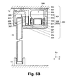
- FIG. 5A illustrates a conventional sliding door system 10, the suspension 200 is attached to a ceiling 13. Unlike the in Figure 1A shown suspension 200 here is the base profile 201 of a plate, due to a screw against a profile 202 is pressed, which rests against the ceiling 13. On a side facing away from the rollers 207 in the z-coordinate direction of the base profile 201, a cover 205 is arranged on this.
- the suspension 300 is designed in this case so that a profile 301 is formed from an intermediate wall portion 318 in the direction of sliding door 11 again as the profile 202 to be replaced.
- the profile 301 is formed as in the first embodiment.
- the suspension 300 can thus be provided with all embodiments of active connections described above.
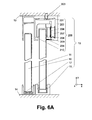
- FIG. 6A shows the sliding door system 10 of FIG. 5A , wherein in addition a side part 16 is present.
- the side part 16 is received at the top in a suspension 200.
- Below the side part 16 is held or stored in a side member receptacle 17.
- an intermediate piece 210 is arranged.
- the intermediate piece 210 separates a sliding door suspension portion of the suspension 200 from a side member receiving portion of the suspension 200.
- a cover portion is formed which optically conceals the upper portion of the side member 16 outwardly.
- the suspension 300 is in turn designed such that a profile 301 is formed from an intermediate wall section 318 in the direction of the sliding door 11 as the profile 202 to be replaced. On the opposite side of the intermediate wall portion 318, the profile 301 is formed as in the first embodiment.
- the suspension 300 can thus be provided with all embodiments of active connections described above.
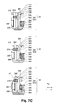
- FIG. 7A shown suspension 300 according to a second embodiment of the invention, a profile 301 and a suspension part 339 for a sliding door 11.
- the suspension part 339 is shaped substantially like the profile 202 to be replaced.
- the suspension part 339 on a side facing away from the sliding door 11 preferably has latching sections 338 at the top and bottom, preferably in the form of projections and / or latching receptacles 337.
- the profile 301 has the suspension part 339 next to a side wall portion 334. Ie. there is no intermediate wall section 318.
- the side wall section 334 has, on the side facing the suspension part 339, according to the design of the suspension part 339, preferably latching receptacles 337 and latching sections 338 at the top and bottom.
- the latching receptacles 337 and / or latching sections 338 are arranged and formed on the suspension part 339 and the profile 301, that the profile 301 mounted or inserted into the suspension part 339 and preferably attached by means of clipping and further preferably due to the locking between locking portions 338 and locking seats 337 safe can be locked.
- This arrangement of latching receptacles 337 and latching projections 338 preferably corresponds to the arrangement of latching receptacles 323 and latching sections 324 with respect to the profile 301 and the cover 302.
- the profile 301 is initially designed as in the second embodiment of the invention described above.
- the side wall section 334 preferably has at least two passage openings 308 which extend in the z-coordinate direction and are arranged one behind the other in the x-coordinate direction.
- preferably threaded bores 212 are formed, which are arranged so that they are aligned with the through holes 308 in the assembled state. Fixing screws 306 are screwed into the threaded bores 212 in the -z coordinate direction through the passage openings 308.
- the passage openings 308 and the threaded bores 212 are selected in number and distributed so that the profile 301, including the drive 303 used and the active connection used, is securely held on the profile 202.
- passage openings 213 are formed, as shown below FIG. 7B shown.
- the fastening screws 306 are screwed through the through-openings 308, 212 at the other end to a nut 214.
- fasteners i. H. Fixing screws 306 in the present case, when attaching the profile 301 on the profile 202 is not or difficult to access.
- a mounting plate 336 is configured to be fixedly attached to the profile 202 of an existing suspension 200.
- the mounting plate 336 has a through hole 308 like the profile 301 according to the third embodiment described above.
- the mounting plate 336 can be fastened by means of fastening screws 306 on the profile 202.
- the mounting plate 336 preferably has latching receptacles 337 and / or latching sections 338 at the top and bottom, similar to the latching receptacles 337 and latching projections 338 in the profile 301 with respect to the in FIG. 7A illustrated suspension part 339.
- the profile 301 On the side facing the mounting plate 336, the profile 301 has correspondingly above and below detent recesses 337 and latching sections 338. This makes it possible to mount or insert and profile the profile 301 into the mounting plate 336 and furthermore preferably to lock it by means of latching.
- the through-holes 308 described herein are preferably countersunk on the side from which a fastening screw 306 is inserted, so countersunk screws can be used and screwed flush.
- passage openings 213, 308 are also possible, as space permits, as shown below, for example FIG. 7B shown.
- the respective fastening screw 306 is arranged to pass through the passage openings 213, 308 and at the other end to be screwed to a nut 214.
- each single roll 207 is typically operatively connected to the respective sliding door 11 via a downwardly facing support.
- the seen in the direction of travel front and rear surfaces of the holder can be used in each case as a stop surface.
- a sliding door with any type of drives can be retrofitted; Retrofitting is independent of the type of suspension of the respective sliding door (s).
- the profile of the retrofit kit according to the embodiments described above is designed so that it can be fixed to a wall or ceiling. This can be done by the retrofit kit also has a wall or ceiling mounting stop for the profile. This makes it possible to continue to use the existing guide rail.
- the embodiments have been described with respect to a respective sliding door.
- the embodiments are each directly operatively connected to a carriage, a single roller holder, a driver or a sliding door.
- each individual sliding door can be retrofitted with its own retrofit kit.
- the covers 302 In the case of a plurality of retrofit sets arranged next to one another in the direction of access, provision can be made for the covers 302 to be connected to one another or to be replaced by a single cover 302 covering all profiles 301.
- a separate rotor can alternatively be provided for each sliding door.
- the coils of the stator which are responsible for a runner at a given moment, must be appropriately controlled in order to move the sliding doors as desired.
- a spindle drive several spindles can be provided. For example, if two sliding doors are to be moved in the same direction, only two spindles with drivers are to be attached to the spindle drive and each operatively connected to a sliding door. If, in this example, the two sliding doors are to be moved in opposite directions, a pitch of the threaded spindle in the respective direction of travel is formed on the spindle for each travel of the respective sliding door. Ie. the gradients for the two sliding doors point in opposite directions.
- Sliding door systems in which several sliding doors are operatively connected to each other, for example, multi-leaf sliding door systems and telescopic sliding door systems.
- These sliding door systems have in common that the sliding doors are usually operatively connected to each other via a cable system and / or a transmission gear, so that the movement of a sliding door causes a predetermined movement of the other sliding door (s).
- the sliding doors are typically each operatively connected by means of a driver with the traction means of the cable system, such as a rope or pull strap, or with the transmission gear.
- the retrofit kit can be operatively connected to one of the drivers.
Landscapes
- Engineering & Computer Science (AREA)
- Mechanical Engineering (AREA)
- Support Devices For Sliding Doors (AREA)
- Power-Operated Mechanisms For Wings (AREA)
Applications Claiming Priority (2)
| Application Number | Priority Date | Filing Date | Title |
|---|---|---|---|
| DE102006061820 | 2006-12-21 | ||
| DE102007041360A DE102007041360B4 (de) | 2006-12-21 | 2007-08-30 | Nachrüstsatz für eine Schiebetür und Schiebetüranlage |
Publications (3)
| Publication Number | Publication Date |
|---|---|
| EP1975355A2 true EP1975355A2 (fr) | 2008-10-01 |
| EP1975355A3 EP1975355A3 (fr) | 2013-10-23 |
| EP1975355B1 EP1975355B1 (fr) | 2015-04-08 |
Family
ID=39431950
Family Applications (1)
| Application Number | Title | Priority Date | Filing Date |
|---|---|---|---|
| EP07023738.3A Revoked EP1975355B1 (fr) | 2006-12-21 | 2007-12-07 | Complément d'équipement pour une porte coulissante et installation de porte coulissante |
Country Status (3)
| Country | Link |
|---|---|
| EP (1) | EP1975355B1 (fr) |
| DE (1) | DE102007041360B4 (fr) |
| ES (1) | ES2539512T3 (fr) |
Cited By (6)
| Publication number | Priority date | Publication date | Assignee | Title |
|---|---|---|---|---|
| EP2549040B1 (fr) | 2011-07-20 | 2017-10-18 | Gebr. Willach GmbH | Structure de support pour une porte coulissante |
| CN108179945A (zh) * | 2017-10-26 | 2018-06-19 | 中山市欧派克五金制品有限公司 | 一种滑动门用直线电机系统 |
| CN113404401A (zh) * | 2021-04-08 | 2021-09-17 | 佛山市磁家有导科技有限公司 | 一种基于链条传动的门窗直线驱动结构 |
| EP3910145A1 (fr) | 2020-05-12 | 2021-11-17 | dormakaba Deutschland GmbH | Installation de porte coulissante |
| CN114207241A (zh) * | 2019-08-08 | 2022-03-18 | 海蒂诗-海因策有限及两合公司 | 滑动门配件、家具和用于组装滑动门配件的方法 |
| JP2023017218A (ja) * | 2021-07-26 | 2023-02-07 | Ykk Ap株式会社 | 建具 |
Families Citing this family (6)
| Publication number | Priority date | Publication date | Assignee | Title |
|---|---|---|---|---|
| DE102009043544B4 (de) * | 2009-09-30 | 2017-01-19 | Dorma Deutschland Gmbh | Sicherung für Anlagen mit zumindest einem entlang eines Verfahrwegs bewegbaren Flügel |
| DE102011056513A1 (de) | 2011-12-16 | 2013-06-20 | Krauss-Maffei Wegmann Gmbh & Co. Kg | Munitionsdepot |
| US10676978B2 (en) * | 2017-06-16 | 2020-06-09 | Todd A. Hohwart | Actuatable sliding panel assembly; retrofit kit and method for retrofitting a sliding panel for mechanically assisted movement between open and closed positions |
| FR3076848B1 (fr) * | 2018-01-12 | 2020-09-11 | Composants Architecturaux Ind Pour Le Batiment | Menuiserie pour une baie de batiment, comprenant un coffre interieur muni de moyens de manœuvre en coulissement d'au moins un organe de transmission |
| CH718059B1 (de) | 2021-12-14 | 2022-07-29 | Gilgen Door Systems Ag | Aufhänganordnung für eine Schiebetür. |
| WO2025099336A1 (fr) * | 2023-11-10 | 2025-05-15 | C3 Systems, S.L. | Fermeture motorisée de panneaux coulissants vitrés |
Citations (2)
| Publication number | Priority date | Publication date | Assignee | Title |
|---|---|---|---|---|
| DE8800862U1 (de) | 1988-01-26 | 1988-03-10 | Hamacher, Walter, 5100 Aachen | Schiebetür |
| DE19842567A1 (de) | 1997-10-10 | 1999-04-15 | Geze Grundstueck Beteiligung | Führungs- und Antriebssystem |
Family Cites Families (7)
| Publication number | Priority date | Publication date | Assignee | Title |
|---|---|---|---|---|
| DE2336310A1 (de) * | 1973-07-17 | 1975-02-06 | Schuermann & Co Heinz | Schiebetuer mit mindestens einem durch einen linearmotor verschiebbaren tuerfluegel |
| EP0883726B1 (fr) * | 1996-03-01 | 1999-09-01 | GEZE Grundstücks- und Beteiligungsgesellschaft mbH | Systeme de porte coulissante |
| DE29607216U1 (de) * | 1996-04-20 | 1997-05-22 | Automatik-Tür-Systeme GmbH, 33378 Rheda-Wiedenbrück | Schiebetüranlage |
| FR2764929B1 (fr) * | 1997-06-20 | 1999-09-03 | Cordver | Porte comprenant au moins un vantail coulissant, notamment pour batiment, a actionnement automatique |
| DE19881621D2 (de) * | 1997-10-29 | 1999-10-28 | Geze Grundstueck Beteiligung | Baukastensystem zur Erstellung von Tür- oder Fensterantrieben |
| US20040074046A1 (en) * | 2002-10-18 | 2004-04-22 | Mimnaugh Gary T. | Adaptable sliding door hanging system |
| ES2246673B1 (es) * | 2003-12-18 | 2007-02-16 | Klein Iberica, S.A. | Dispositivo para el accionamiento sincronizado de puertas correderas. |
-
2007
- 2007-08-30 DE DE102007041360A patent/DE102007041360B4/de not_active Revoked
- 2007-12-07 ES ES07023738.3T patent/ES2539512T3/es active Active
- 2007-12-07 EP EP07023738.3A patent/EP1975355B1/fr not_active Revoked
Patent Citations (2)
| Publication number | Priority date | Publication date | Assignee | Title |
|---|---|---|---|---|
| DE8800862U1 (de) | 1988-01-26 | 1988-03-10 | Hamacher, Walter, 5100 Aachen | Schiebetür |
| DE19842567A1 (de) | 1997-10-10 | 1999-04-15 | Geze Grundstueck Beteiligung | Führungs- und Antriebssystem |
Cited By (10)
| Publication number | Priority date | Publication date | Assignee | Title |
|---|---|---|---|---|
| EP2549040B1 (fr) | 2011-07-20 | 2017-10-18 | Gebr. Willach GmbH | Structure de support pour une porte coulissante |
| EP2549040B2 (fr) † | 2011-07-20 | 2022-09-28 | Gebr. Willach GmbH | Combinaison d'une structure de support et d'un chariot pour une porte coulissante |
| CN108179945A (zh) * | 2017-10-26 | 2018-06-19 | 中山市欧派克五金制品有限公司 | 一种滑动门用直线电机系统 |
| CN108179945B (zh) * | 2017-10-26 | 2023-11-03 | 中山市欧派克五金制品有限公司 | 一种滑动门用直线电机系统 |
| CN114207241A (zh) * | 2019-08-08 | 2022-03-18 | 海蒂诗-海因策有限及两合公司 | 滑动门配件、家具和用于组装滑动门配件的方法 |
| CN114207241B (zh) * | 2019-08-08 | 2023-12-15 | 海蒂诗-海因策有限及两合公司 | 滑动门配件、家具和用于组装滑动门配件的方法 |
| EP3910145A1 (fr) | 2020-05-12 | 2021-11-17 | dormakaba Deutschland GmbH | Installation de porte coulissante |
| DE102020112883A1 (de) | 2020-05-12 | 2021-11-18 | Dormakaba Deutschland Gmbh | Schiebetüranlage |
| CN113404401A (zh) * | 2021-04-08 | 2021-09-17 | 佛山市磁家有导科技有限公司 | 一种基于链条传动的门窗直线驱动结构 |
| JP2023017218A (ja) * | 2021-07-26 | 2023-02-07 | Ykk Ap株式会社 | 建具 |
Also Published As
| Publication number | Publication date |
|---|---|
| EP1975355A3 (fr) | 2013-10-23 |
| EP1975355B1 (fr) | 2015-04-08 |
| ES2539512T3 (es) | 2015-07-01 |
| DE102007041360B4 (de) | 2013-05-08 |
| DE102007041360A1 (de) | 2008-06-26 |
Similar Documents
| Publication | Publication Date | Title |
|---|---|---|
| EP1975355B1 (fr) | Complément d'équipement pour une porte coulissante et installation de porte coulissante | |
| DE102007013446B4 (de) | Elektrisches Stellglied | |
| EP1550784B1 (fr) | Dispositif d'entraînement de gâche pour une serrure de véhicule | |
| EP2176487A1 (fr) | Suspension de porte coulissante avec entraînement linéaire intégré | |
| EP2161400A2 (fr) | Ensemble de rééquipement doté d'une unité d'entraînement, notamment pour une porte coulissante automatique | |
| DE102009011120B4 (de) | Einstelleinrichtung für die Fensterscheibe eines Fensterhebers | |
| DE29606992U1 (de) | Für eine Rastmontage eingerichteter Stangenverschluß | |
| EP2176483A1 (fr) | Dispositif d'entraînement pour porte coulissante | |
| EP3859107B1 (fr) | Porte coulissante | |
| DE202012012514U1 (de) | Spiraltor | |
| DE102011056416B4 (de) | Anordnung einer Antriebseinheit einer Ausstell- oder Verriegelungseinrichtung | |
| DE202010001159U1 (de) | Mitnehmer für eine Verstellvorrichtung zum Verstellen eines Fahrzeugteils | |
| DE19842567C5 (de) | Führungs- und Antriebssystem | |
| WO2012016689A1 (fr) | Chariot de porte coulissante modulaire | |
| EP2341201B1 (fr) | Bloc d'armature pour une fenêtre, une porte, un clapet ou analogue | |
| DE102008046518A1 (de) | Rollenförderer mit Zugmittelantrieb | |
| DE202016001381U1 (de) | Antrieb mit einer Verstellvorrichtung für einen verschiebbaren Flügel als Hebe-Schiebekippflügel oder Hebe-Schiebeflügel | |
| EP2161401B1 (fr) | Agencement de liaison d'un moyen de traction et d'un élément d'entraîneur | |
| EP1840312A2 (fr) | Porte coulissante | |
| DE1555632B2 (fr) | ||
| EP4532877B1 (fr) | Unité fonctionnelle dotée d'un compartiment de porte pour une porte maintenue coulissante | |
| DE102007030139B4 (de) | Verstellantrieb zur Bewegung eines Funktionselementes in oder an einer Kraftfahrzeugkarosserie | |
| DE102013000178A1 (de) | Automatische Schiebetür | |
| DE102008040842A1 (de) | Antriebsgehäuse für einen Treibstangenbeschlag | |
| DE2417101B2 (de) | Kantenverschluß für Türen o.dgl. |
Legal Events
| Date | Code | Title | Description |
|---|---|---|---|
| PUAI | Public reference made under article 153(3) epc to a published international application that has entered the european phase |
Free format text: ORIGINAL CODE: 0009012 |
|
| AK | Designated contracting states |
Kind code of ref document: A2 Designated state(s): AT BE BG CH CY CZ DE DK EE ES FI FR GB GR HU IE IS IT LI LT LU LV MC MT NL PL PT RO SE SI SK TR |
|
| AX | Request for extension of the european patent |
Extension state: AL BA HR MK RS |
|
| RAP1 | Party data changed (applicant data changed or rights of an application transferred) |
Owner name: DORMA GMBH + CO. KG |
|
| RIC1 | Information provided on ipc code assigned before grant |
Ipc: E05F 15/14 20060101ALI20130611BHEP Ipc: E05D 15/06 20060101AFI20130611BHEP |
|
| PUAL | Search report despatched |
Free format text: ORIGINAL CODE: 0009013 |
|
| AK | Designated contracting states |
Kind code of ref document: A3 Designated state(s): AT BE BG CH CY CZ DE DK EE ES FI FR GB GR HU IE IS IT LI LT LU LV MC MT NL PL PT RO SE SI SK TR |
|
| AX | Request for extension of the european patent |
Extension state: AL BA HR MK RS |
|
| RIC1 | Information provided on ipc code assigned before grant |
Ipc: E05F 15/14 20060101ALI20130916BHEP Ipc: E05D 15/06 20060101AFI20130916BHEP |
|
| 17P | Request for examination filed |
Effective date: 20140423 |
|
| RBV | Designated contracting states (corrected) |
Designated state(s): AT BE BG CH CY CZ DE DK EE ES FI FR GB GR HU IE IS IT LI LT LU LV MC MT NL PL PT RO SE SI SK TR |
|
| AKX | Designation fees paid |
Designated state(s): AT BE BG CH CY CZ DE DK EE ES FI FR GB GR HU IE IS IT LI LT LU LV MC MT NL PL PT RO SE SI SK TR |
|
| GRAP | Despatch of communication of intention to grant a patent |
Free format text: ORIGINAL CODE: EPIDOSNIGR1 |
|
| INTG | Intention to grant announced |
Effective date: 20150121 |
|
| RIC1 | Information provided on ipc code assigned before grant |
Ipc: E05F 15/643 20150101ALI20150115BHEP Ipc: E05F 15/652 20150101ALI20150115BHEP Ipc: E05F 15/632 20150101ALI20150115BHEP Ipc: E05D 15/06 20060101AFI20150115BHEP |
|
| GRAS | Grant fee paid |
Free format text: ORIGINAL CODE: EPIDOSNIGR3 |
|
| GRAA | (expected) grant |
Free format text: ORIGINAL CODE: 0009210 |
|
| AK | Designated contracting states |
Kind code of ref document: B1 Designated state(s): AT BE BG CH CY CZ DE DK EE ES FI FR GB GR HU IE IS IT LI LT LU LV MC MT NL PL PT RO SE SI SK TR |
|
| RAP1 | Party data changed (applicant data changed or rights of an application transferred) |
Owner name: DORMA DEUTSCHLAND GMBH |
|
| REG | Reference to a national code |
Ref country code: GB Ref legal event code: FG4D Free format text: NOT ENGLISH |
|
| REG | Reference to a national code |
Ref country code: CH Ref legal event code: EP |
|
| REG | Reference to a national code |
Ref country code: IE Ref legal event code: FG4D Free format text: LANGUAGE OF EP DOCUMENT: GERMAN |
|
| REG | Reference to a national code |
Ref country code: AT Ref legal event code: REF Ref document number: 720717 Country of ref document: AT Kind code of ref document: T Effective date: 20150515 |
|
| REG | Reference to a national code |
Ref country code: DE Ref legal event code: R096 Ref document number: 502007013850 Country of ref document: DE Effective date: 20150521 |
|
| REG | Reference to a national code |
Ref country code: ES Ref legal event code: FG2A Ref document number: 2539512 Country of ref document: ES Kind code of ref document: T3 Effective date: 20150701 |
|
| REG | Reference to a national code |
Ref country code: NL Ref legal event code: VDEP Effective date: 20150408 |
|
| REG | Reference to a national code |
Ref country code: LT Ref legal event code: MG4D |
|
| PG25 | Lapsed in a contracting state [announced via postgrant information from national office to epo] |
Ref country code: NL Free format text: LAPSE BECAUSE OF FAILURE TO SUBMIT A TRANSLATION OF THE DESCRIPTION OR TO PAY THE FEE WITHIN THE PRESCRIBED TIME-LIMIT Effective date: 20150408 |
|
| PG25 | Lapsed in a contracting state [announced via postgrant information from national office to epo] |
Ref country code: LT Free format text: LAPSE BECAUSE OF FAILURE TO SUBMIT A TRANSLATION OF THE DESCRIPTION OR TO PAY THE FEE WITHIN THE PRESCRIBED TIME-LIMIT Effective date: 20150408 Ref country code: FI Free format text: LAPSE BECAUSE OF FAILURE TO SUBMIT A TRANSLATION OF THE DESCRIPTION OR TO PAY THE FEE WITHIN THE PRESCRIBED TIME-LIMIT Effective date: 20150408 Ref country code: PT Free format text: LAPSE BECAUSE OF FAILURE TO SUBMIT A TRANSLATION OF THE DESCRIPTION OR TO PAY THE FEE WITHIN THE PRESCRIBED TIME-LIMIT Effective date: 20150810 |
|
| PG25 | Lapsed in a contracting state [announced via postgrant information from national office to epo] |
Ref country code: IS Free format text: LAPSE BECAUSE OF FAILURE TO SUBMIT A TRANSLATION OF THE DESCRIPTION OR TO PAY THE FEE WITHIN THE PRESCRIBED TIME-LIMIT Effective date: 20150808 Ref country code: LV Free format text: LAPSE BECAUSE OF FAILURE TO SUBMIT A TRANSLATION OF THE DESCRIPTION OR TO PAY THE FEE WITHIN THE PRESCRIBED TIME-LIMIT Effective date: 20150408 Ref country code: GR Free format text: LAPSE BECAUSE OF FAILURE TO SUBMIT A TRANSLATION OF THE DESCRIPTION OR TO PAY THE FEE WITHIN THE PRESCRIBED TIME-LIMIT Effective date: 20150709 |
|
| REG | Reference to a national code |
Ref country code: FR Ref legal event code: PLFP Year of fee payment: 9 |
|
| REG | Reference to a national code |
Ref country code: DE Ref legal event code: R026 Ref document number: 502007013850 Country of ref document: DE |
|
| PLBI | Opposition filed |
Free format text: ORIGINAL CODE: 0009260 |
|
| PG25 | Lapsed in a contracting state [announced via postgrant information from national office to epo] |
Ref country code: EE Free format text: LAPSE BECAUSE OF FAILURE TO SUBMIT A TRANSLATION OF THE DESCRIPTION OR TO PAY THE FEE WITHIN THE PRESCRIBED TIME-LIMIT Effective date: 20150408 Ref country code: DK Free format text: LAPSE BECAUSE OF FAILURE TO SUBMIT A TRANSLATION OF THE DESCRIPTION OR TO PAY THE FEE WITHIN THE PRESCRIBED TIME-LIMIT Effective date: 20150408 |
|
| PLAB | Opposition data, opponent's data or that of the opponent's representative modified |
Free format text: ORIGINAL CODE: 0009299OPPO |
|
| PLAX | Notice of opposition and request to file observation + time limit sent |
Free format text: ORIGINAL CODE: EPIDOSNOBS2 |
|
| 26 | Opposition filed |
Opponent name: GEZE GMBH Effective date: 20160107 |
|
| PG25 | Lapsed in a contracting state [announced via postgrant information from national office to epo] |
Ref country code: PL Free format text: LAPSE BECAUSE OF FAILURE TO SUBMIT A TRANSLATION OF THE DESCRIPTION OR TO PAY THE FEE WITHIN THE PRESCRIBED TIME-LIMIT Effective date: 20150408 Ref country code: CZ Free format text: LAPSE BECAUSE OF FAILURE TO SUBMIT A TRANSLATION OF THE DESCRIPTION OR TO PAY THE FEE WITHIN THE PRESCRIBED TIME-LIMIT Effective date: 20150408 Ref country code: RO Free format text: LAPSE BECAUSE OF NON-PAYMENT OF DUE FEES Effective date: 20150408 Ref country code: SK Free format text: LAPSE BECAUSE OF FAILURE TO SUBMIT A TRANSLATION OF THE DESCRIPTION OR TO PAY THE FEE WITHIN THE PRESCRIBED TIME-LIMIT Effective date: 20150408 |
|
| R26 | Opposition filed (corrected) |
Opponent name: GEZE GMBH Effective date: 20160107 |
|
| PG25 | Lapsed in a contracting state [announced via postgrant information from national office to epo] |
Ref country code: BE Free format text: LAPSE BECAUSE OF NON-PAYMENT OF DUE FEES Effective date: 20151231 Ref country code: SI Free format text: LAPSE BECAUSE OF FAILURE TO SUBMIT A TRANSLATION OF THE DESCRIPTION OR TO PAY THE FEE WITHIN THE PRESCRIBED TIME-LIMIT Effective date: 20150408 |
|
| PLBB | Reply of patent proprietor to notice(s) of opposition received |
Free format text: ORIGINAL CODE: EPIDOSNOBS3 |
|
| PG25 | Lapsed in a contracting state [announced via postgrant information from national office to epo] |
Ref country code: LU Free format text: LAPSE BECAUSE OF FAILURE TO SUBMIT A TRANSLATION OF THE DESCRIPTION OR TO PAY THE FEE WITHIN THE PRESCRIBED TIME-LIMIT Effective date: 20151207 Ref country code: MC Free format text: LAPSE BECAUSE OF FAILURE TO SUBMIT A TRANSLATION OF THE DESCRIPTION OR TO PAY THE FEE WITHIN THE PRESCRIBED TIME-LIMIT Effective date: 20150408 |
|
| REG | Reference to a national code |
Ref country code: CH Ref legal event code: PL |
|
| REG | Reference to a national code |
Ref country code: IE Ref legal event code: MM4A |
|
| PG25 | Lapsed in a contracting state [announced via postgrant information from national office to epo] |
Ref country code: CH Free format text: LAPSE BECAUSE OF NON-PAYMENT OF DUE FEES Effective date: 20151231 Ref country code: IE Free format text: LAPSE BECAUSE OF NON-PAYMENT OF DUE FEES Effective date: 20151207 Ref country code: LI Free format text: LAPSE BECAUSE OF NON-PAYMENT OF DUE FEES Effective date: 20151231 |
|
| REG | Reference to a national code |
Ref country code: FR Ref legal event code: PLFP Year of fee payment: 10 |
|
| REG | Reference to a national code |
Ref country code: AT Ref legal event code: MM01 Ref document number: 720717 Country of ref document: AT Kind code of ref document: T Effective date: 20151207 |
|
| REG | Reference to a national code |
Ref country code: DE Ref legal event code: R082 Ref document number: 502007013850 Country of ref document: DE Representative=s name: BALDER IP LAW, S.L., ES Ref country code: DE Ref legal event code: R081 Ref document number: 502007013850 Country of ref document: DE Owner name: DORMAKABA DEUTSCHLAND GMBH, DE Free format text: FORMER OWNER: DORMA DEUTSCHLAND GMBH, 58256 ENNEPETAL, DE |
|
| PG25 | Lapsed in a contracting state [announced via postgrant information from national office to epo] |
Ref country code: HU Free format text: LAPSE BECAUSE OF FAILURE TO SUBMIT A TRANSLATION OF THE DESCRIPTION OR TO PAY THE FEE WITHIN THE PRESCRIBED TIME-LIMIT; INVALID AB INITIO Effective date: 20071207 Ref country code: BG Free format text: LAPSE BECAUSE OF FAILURE TO SUBMIT A TRANSLATION OF THE DESCRIPTION OR TO PAY THE FEE WITHIN THE PRESCRIBED TIME-LIMIT Effective date: 20150408 Ref country code: AT Free format text: LAPSE BECAUSE OF NON-PAYMENT OF DUE FEES Effective date: 20151207 |
|
| PG25 | Lapsed in a contracting state [announced via postgrant information from national office to epo] |
Ref country code: SE Free format text: LAPSE BECAUSE OF FAILURE TO SUBMIT A TRANSLATION OF THE DESCRIPTION OR TO PAY THE FEE WITHIN THE PRESCRIBED TIME-LIMIT Effective date: 20150408 Ref country code: CY Free format text: LAPSE BECAUSE OF FAILURE TO SUBMIT A TRANSLATION OF THE DESCRIPTION OR TO PAY THE FEE WITHIN THE PRESCRIBED TIME-LIMIT Effective date: 20150408 |
|
| PG25 | Lapsed in a contracting state [announced via postgrant information from national office to epo] |
Ref country code: MT Free format text: LAPSE BECAUSE OF FAILURE TO SUBMIT A TRANSLATION OF THE DESCRIPTION OR TO PAY THE FEE WITHIN THE PRESCRIBED TIME-LIMIT Effective date: 20150408 Ref country code: TR Free format text: LAPSE BECAUSE OF FAILURE TO SUBMIT A TRANSLATION OF THE DESCRIPTION OR TO PAY THE FEE WITHIN THE PRESCRIBED TIME-LIMIT Effective date: 20150408 |
|
| REG | Reference to a national code |
Ref country code: ES Ref legal event code: PC2A Owner name: DORMAKABA DEUTSCHLAND GMBH Effective date: 20171004 |
|
| REG | Reference to a national code |
Ref country code: FR Ref legal event code: CD Owner name: DORMA DEUTSCHLAND GMBH, DE Effective date: 20171003 |
|
| PLCK | Communication despatched that opposition was rejected |
Free format text: ORIGINAL CODE: EPIDOSNREJ1 |
|
| STAA | Information on the status of an ep patent application or granted ep patent |
Free format text: STATUS: THE PATENT HAS BEEN GRANTED |
|
| REG | Reference to a national code |
Ref country code: FR Ref legal event code: PLFP Year of fee payment: 11 |
|
| APBM | Appeal reference recorded |
Free format text: ORIGINAL CODE: EPIDOSNREFNO |
|
| APBP | Date of receipt of notice of appeal recorded |
Free format text: ORIGINAL CODE: EPIDOSNNOA2O |
|
| APAH | Appeal reference modified |
Free format text: ORIGINAL CODE: EPIDOSCREFNO |
|
| APAH | Appeal reference modified |
Free format text: ORIGINAL CODE: EPIDOSCREFNO |
|
| APBQ | Date of receipt of statement of grounds of appeal recorded |
Free format text: ORIGINAL CODE: EPIDOSNNOA3O |
|
| PGFP | Annual fee paid to national office [announced via postgrant information from national office to epo] |
Ref country code: GB Payment date: 20211221 Year of fee payment: 15 Ref country code: FR Payment date: 20211224 Year of fee payment: 15 Ref country code: DE Payment date: 20211210 Year of fee payment: 15 |
|
| REG | Reference to a national code |
Ref country code: DE Ref legal event code: R103 Ref document number: 502007013850 Country of ref document: DE Ref country code: DE Ref legal event code: R064 Ref document number: 502007013850 Country of ref document: DE |
|
| APBU | Appeal procedure closed |
Free format text: ORIGINAL CODE: EPIDOSNNOA9O |
|
| PGFP | Annual fee paid to national office [announced via postgrant information from national office to epo] |
Ref country code: IT Payment date: 20211224 Year of fee payment: 15 Ref country code: ES Payment date: 20220218 Year of fee payment: 15 |
|
| RDAF | Communication despatched that patent is revoked |
Free format text: ORIGINAL CODE: EPIDOSNREV1 |
|
| STAA | Information on the status of an ep patent application or granted ep patent |
Free format text: STATUS: PATENT REVOKED |
|
| RDAG | Patent revoked |
Free format text: ORIGINAL CODE: 0009271 |
|
| REG | Reference to a national code |
Ref country code: FI Ref legal event code: MGE |
|
| 27W | Patent revoked |
Effective date: 20220506 |
|
| GBPR | Gb: patent revoked under art. 102 of the ep convention designating the uk as contracting state |
Effective date: 20220506 |