EP1975452A2 - Capteur d'usure - Google Patents
Capteur d'usure Download PDFInfo
- Publication number
- EP1975452A2 EP1975452A2 EP08152811A EP08152811A EP1975452A2 EP 1975452 A2 EP1975452 A2 EP 1975452A2 EP 08152811 A EP08152811 A EP 08152811A EP 08152811 A EP08152811 A EP 08152811A EP 1975452 A2 EP1975452 A2 EP 1975452A2
- Authority
- EP
- European Patent Office
- Prior art keywords
- fact
- sensor according
- block
- friction material
- electrical wiring
- Prior art date
- Legal status (The legal status is an assumption and is not a legal conclusion. Google has not performed a legal analysis and makes no representation as to the accuracy of the status listed.)
- Granted
Links
Images

Classifications
-
- F—MECHANICAL ENGINEERING; LIGHTING; HEATING; WEAPONS; BLASTING
- F16—ENGINEERING ELEMENTS AND UNITS; GENERAL MEASURES FOR PRODUCING AND MAINTAINING EFFECTIVE FUNCTIONING OF MACHINES OR INSTALLATIONS; THERMAL INSULATION IN GENERAL
- F16D—COUPLINGS FOR TRANSMITTING ROTATION; CLUTCHES; BRAKES
- F16D66/00—Arrangements for monitoring working conditions, e.g. wear, temperature
- F16D66/02—Apparatus for indicating wear
- F16D66/021—Apparatus for indicating wear using electrical detection or indication means
- F16D66/022—Apparatus for indicating wear using electrical detection or indication means indicating that a lining is worn to minimum allowable thickness
- F16D66/023—Apparatus for indicating wear using electrical detection or indication means indicating that a lining is worn to minimum allowable thickness directly sensing the position of braking members
- F16D66/024—Sensors mounted on braking members adapted to contact the brake disc or drum, e.g. wire loops severed on contact
-
- F—MECHANICAL ENGINEERING; LIGHTING; HEATING; WEAPONS; BLASTING
- F16—ENGINEERING ELEMENTS AND UNITS; GENERAL MEASURES FOR PRODUCING AND MAINTAINING EFFECTIVE FUNCTIONING OF MACHINES OR INSTALLATIONS; THERMAL INSULATION IN GENERAL
- F16D—COUPLINGS FOR TRANSMITTING ROTATION; CLUTCHES; BRAKES
- F16D2250/00—Manufacturing; Assembly
- F16D2250/0084—Assembly or disassembly
Definitions
- the present invention relates to a wear sensor for a braking member, in particular a brake pad for vehicles, to which the following description will explicitly refer without any loss of its generality.
- a brake pad for vehicles comprises a support plate, a block of friction material carried by the support plate, and a wear sensor to detect a wear limit condition of the block of friction material and order the emission of an acoustic or optical signal informing the driver of the need to replace the friction material.
- the wear sensor comprises electrical wiring that may or may not be insulated, a terminal section of the free extremity of which is housed in a blind hole obtained in the block of friction material and is retained within said hole, for example, by means of gluing material interposed between the terminal section and the block of friction material.
- the terminal section of the electrical wiring may end up in a functional position in which it is partially extracted and thus different from the normal fully inserted position. It follows that, when the terminal section is arranged in said partially extracted position, the sensor does not send signals or sends them after a delay in relation to the moment in which the friction material reaches its wear limit condition compromising, in this way, the proper functioning of the braking members but, above all, putting the safety of the persons on board the vehicle at risk.
- the aim of the present invention is to provide a wear sensor with constructional characteristics that are able to overcome the disadvantages described above in a simple and cost-effective manner, and which continues to be efficient and functionally reliable over time, and also involves limited implementation costs.
- a wear sensor is produced for a braking member of a vehicle, comprising a block of friction material suitable to cooperate frictionally with a relative metal braking member; the sensor comprising electrical wiring and a detection portion connected to said electrical wiring and suitable to be joined to said block of friction material in a fixed operating position of reference for the detection of a wear limit state of the block of friction material, and characterized by the fact of further comprising a collar member distinct from said electrical wiring and from said braking member to visibly detect from the outside when said detection portion is in a position other than said fixed operating position of reference.
- the detection portion consists of a terminal section of said electrical wiring, and the collar member is only connected to an intermediate portion of said wiring.
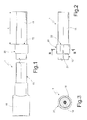
- number 1 indicates, as a whole, a wear sensor for the detection of a wear limit condition of a braking member 2 for a vehicle, for example, a brake pad.
- the braking member 2 comprises a block 4 of friction material, and a supporting member 5 of said block 4 of friction material.
- the block 4 of friction material is delimited, on one side, by a friction surface 6 suitable to cooperate frictionally with a brake disk 7, and is provided with a blind hole 8 extending for a predefined length A starting at the surface 10 opposite the surface 6 orthogonal to said surface 6.
- the sensor 1 comprises insulated electrical wiring 13 in turn comprising ( Figure 3 ) a core 14 of conductor material and an external sheath 15 made of insulating material.
- the electrical wiring 13 has one extremity connected to an electrical connector 16 for the connection of the electrical wiring 13 to a cable bundle of the vehicle (not illustrated), and an opposite terminal section 18, the length L of which approximated by defect corresponds to the depth A of the hole 8 and which is completely inserted in said hole 8 and conveniently retained therein in a fixed position of reference, through the interposition of gluing material.
- the terminal section 18 is retained within the blind hole 8 by elastic devices or metal brackets, of a known type.
- the senor 1 further comprises a collar member 20 suitable to enable an operator to visibly detect from the outside an irregular positioning of the section 18, that is, a condition of insertion or operation in which the terminal section 18 is partially or completely extracted from the blind hole 8 and therefore arranged in a position that is different from the correct fixed operating position of reference.
- the collar member 20 consists of an open ring fitted on an intermediate portion 21 of the electrical wiring 13 close to the terminal section 18, has an outside diameter greater than that of the hole 8, and is delimited, on the part facing the terminal section 18, by an annular frontal surface or shoulder 22. In this way, when the terminal section 18 is inserted in the hole 8 and placed in its fixed operating position of reference, the surface 22 rests against the surface 10 of the block 4 of friction material.
- the annular surface 22 is arranged at a distance from the free extremity of the terminal section 18 greater than the distance L and the length A, and therefore, when completely inserted, the surface 22 is distanced from the surface 10.
- the collar member 20 comprises a radial appendage 25 which, when the section 18 is arranged in its fixed operating position of reference, rests against the supporting member 5.
- the radial appendage 25 rests against a sound-reducing plate of the braking member.
- the collar member 20 is made of plastically deformable material, conveniently metal and preferably a brass or aluminum alloy, and is plastically deformed directly above said electrical wiring 13.
- the collar member 20 is joined to the wiring 13 by means of an interference coupling exploiting the elasticity of the insulating sheathing of said wiring 13 or of said collar member 20.
- the collar member 20 is permanently connected to the wiring 13 by means of the interposition of a gluing material or by means of a thermobonding operation.
- the constructional characteristics of the wear sensor 1 and, in particular, the presence of the collar member 20 permanently connected to the electrical wiring 13 enable a technician to visibly detect from the outside and in an extremely simple and immediate manner and, above all, at any time during the functional life of the braking member 2 starting from the time of insertion of the terminal section 18 in the blind hole 8, the possible irregular position of the terminal section 18 in relation to the block 4 of friction material.
- the collar member 20 enables a technician to detect from the time of assembly when the terminal section 18 is in a position different from the predetermined operating position of reference so as to report production defects or those emerging during use.
- the collar member 20 When the terminal section 18 is in a position different from the fixed position of reference, the collar member 20 is spaced away from the block 4 of material and the deviation of the surface 22 from the surface 10 of the block 4 of said friction material or the deviation of the appendage 25 from the supporting body 5 or from the sound-reducing plate should the appendage 25 be arranged so as to rest against the latter, is clear.
- the collar member 20 precisely because it is made of metal, is practically insensitive to temperature, unlike other materials, and therefore its physical and mechanical properties remain unchanged even when it operates at high temperatures and in the presence of water and/or external contaminants.
- the collar member 20 can be secured to the electrical wiring 13 of the sensor 1 without the need to modify the current moulds used to make said sensor and/or to use plastic materials other than those normally used for the forming of the sensor.
- the particular collar or ring shape combined with the metal facilitates, on the one hand, the coupling of the member 20 to the wiring 13 and, on the other hand, the blocking by means of simple plastic deformation, as this operation can be carried out during a completely automatic forming cycle and thus keeping costs particularly low.
- the described wear sensor 1 can be modified and varied without departing from the scope of the invention as defined by the claims.
- the collar member 20 could be embodied in a way that is different from that indicated by way of example.
- the sensor 1 could comprise a connection portion permanently connected to the wiring, and a stop portion that simply rests against a surface of reference that is fixed in relation to the braking member. In this respect it is clear that said stop portion could also rest against connection appendages or brackets already present or foreseeable on the braking member.
- collar member 20 could be made only partially of metal and the material used could be different from that indicated by way of example.
Landscapes
- Engineering & Computer Science (AREA)
- General Engineering & Computer Science (AREA)
- Mechanical Engineering (AREA)
- Braking Arrangements (AREA)
- Investigating Or Analyzing Materials By The Use Of Fluid Adsorption Or Reactions (AREA)
Applications Claiming Priority (1)
| Application Number | Priority Date | Filing Date | Title |
|---|---|---|---|
| ITTO20070041 ITTO20070041U1 (it) | 2007-03-16 | 2007-03-16 | Sensore d'usura |
Publications (3)
| Publication Number | Publication Date |
|---|---|
| EP1975452A2 true EP1975452A2 (fr) | 2008-10-01 |
| EP1975452A3 EP1975452A3 (fr) | 2009-04-08 |
| EP1975452B1 EP1975452B1 (fr) | 2014-08-27 |
Family
ID=39639349
Family Applications (1)
| Application Number | Title | Priority Date | Filing Date |
|---|---|---|---|
| EP20080152811 Active EP1975452B1 (fr) | 2007-03-16 | 2008-03-14 | Capteur d'usure |
Country Status (3)
| Country | Link |
|---|---|
| EP (1) | EP1975452B1 (fr) |
| ES (1) | ES2520040T3 (fr) |
| IT (1) | ITTO20070041U1 (fr) |
Cited By (2)
| Publication number | Priority date | Publication date | Assignee | Title |
|---|---|---|---|---|
| WO2017109282A1 (fr) * | 2015-12-21 | 2017-06-29 | Outotec (Finland) Oy | Procédé et système pour le suivi de l'état d'un élément d'usure, utilisation du procédé et du système et four de frittage sur bande |
| IT202200008516A1 (it) * | 2022-04-28 | 2023-10-28 | Fca Italy Spa | Pastiglia freno per veicoli, e procedimento per montare un sensore in tale pastiglia freno |
Family Cites Families (2)
| Publication number | Priority date | Publication date | Assignee | Title |
|---|---|---|---|---|
| FR2266056A1 (en) * | 1974-03-25 | 1975-10-24 | Cama Michel | Wear detector for disc brakes - has insulating probe cover worn away to close signal circuit |
| JP4011169B2 (ja) * | 1997-12-12 | 2007-11-21 | 曙ブレーキ工業株式会社 | ウェアインジケータ付ブレーキ素子 |
-
2007
- 2007-03-16 IT ITTO20070041 patent/ITTO20070041U1/it unknown
-
2008
- 2008-03-14 ES ES08152811.9T patent/ES2520040T3/es active Active
- 2008-03-14 EP EP20080152811 patent/EP1975452B1/fr active Active
Non-Patent Citations (1)
| Title |
|---|
| None |
Cited By (2)
| Publication number | Priority date | Publication date | Assignee | Title |
|---|---|---|---|---|
| WO2017109282A1 (fr) * | 2015-12-21 | 2017-06-29 | Outotec (Finland) Oy | Procédé et système pour le suivi de l'état d'un élément d'usure, utilisation du procédé et du système et four de frittage sur bande |
| IT202200008516A1 (it) * | 2022-04-28 | 2023-10-28 | Fca Italy Spa | Pastiglia freno per veicoli, e procedimento per montare un sensore in tale pastiglia freno |
Also Published As
| Publication number | Publication date |
|---|---|
| EP1975452A3 (fr) | 2009-04-08 |
| EP1975452B1 (fr) | 2014-08-27 |
| ES2520040T3 (es) | 2014-11-11 |
| ITTO20070041U1 (it) | 2008-09-17 |
Similar Documents
| Publication | Publication Date | Title |
|---|---|---|
| US11259416B2 (en) | Fitting element | |
| US10197251B2 (en) | Fastening element for fixating two components at each other | |
| CN101513867B (zh) | 用于电动停车制动器的停车线缆的连接装置 | |
| KR101977714B1 (ko) | 브레이크 마찰 패드의 마모감지장치 | |
| US20100281684A1 (en) | Cable harness production system | |
| WO2008132407A3 (fr) | Dispositif d'insertion et de sertissage de bague pour fixation a bague sertie sur une tige | |
| CA2747668C (fr) | Dispositif de soupape | |
| US11332170B2 (en) | Triggering monitoring device for a deformation tube for a coupling; and train coupling | |
| EP1975452A2 (fr) | Capteur d'usure | |
| US20180306256A1 (en) | Multiple function brake caliper guide pin | |
| US8708429B2 (en) | Hydraulic braking assembly for a vehicle comprising a hydraulic fluid level sensor | |
| EP1798440A1 (fr) | Capteur d'usure de garniture de frein | |
| JP2013101932A (ja) | 電子ユニットの電気的コンタクトを行うための装置 | |
| JP2016038378A5 (fr) | ||
| WO2002012004A1 (fr) | Connecteur electrique tracteur / remorque muni d'un detecteur de connexion electrique | |
| EP1978273B1 (fr) | Capteur d'usure | |
| US5584216A (en) | Tool with breakage sensor and method | |
| EP0830696B1 (fr) | Composant dote d'une terminaison electrique a la fois rigide et flexible | |
| WO2015122267A1 (fr) | Structure de fixation d'électroaimant | |
| JP5662355B2 (ja) | リバーシブルベルトテンショナ | |
| EP1474619A2 (fr) | Systeme de fixation d'un element de connexion electrique sur un etrier de frein a disque | |
| CN211869357U (zh) | 卡簧自锁式连接件及应用该连接件的感应头 | |
| JP2003050162A (ja) | 光ファイバー折曲器 | |
| CN202676200U (zh) | 一种皮带轮反装检测装置 | |
| EP4249335A1 (fr) | Étrier de frein, dispositif d'indication d'usure correspondant et frein de véhicule |
Legal Events
| Date | Code | Title | Description |
|---|---|---|---|
| PUAI | Public reference made under article 153(3) epc to a published international application that has entered the european phase |
Free format text: ORIGINAL CODE: 0009012 |
|
| AK | Designated contracting states |
Kind code of ref document: A2 Designated state(s): AT BE BG CH CY CZ DE DK EE ES FI FR GB GR HR HU IE IS IT LI LT LU LV MC MT NL NO PL PT RO SE SI SK TR |
|
| AX | Request for extension of the european patent |
Extension state: AL BA MK RS |
|
| PUAL | Search report despatched |
Free format text: ORIGINAL CODE: 0009013 |
|
| AK | Designated contracting states |
Kind code of ref document: A3 Designated state(s): AT BE BG CH CY CZ DE DK EE ES FI FR GB GR HR HU IE IS IT LI LT LU LV MC MT NL NO PL PT RO SE SI SK TR |
|
| AX | Request for extension of the european patent |
Extension state: AL BA MK RS |
|
| 17P | Request for examination filed |
Effective date: 20091007 |
|
| AKX | Designation fees paid |
Designated state(s): AT BE BG CH CY CZ DE DK EE ES FI FR GB GR HR HU IE IS IT LI LT LU LV MC MT NL NO PL PT RO SE SI SK TR |
|
| 17Q | First examination report despatched |
Effective date: 20091124 |
|
| RAP1 | Party data changed (applicant data changed or rights of an application transferred) |
Owner name: I.C.P. S.R.L. |
|
| GRAP | Despatch of communication of intention to grant a patent |
Free format text: ORIGINAL CODE: EPIDOSNIGR1 |
|
| INTG | Intention to grant announced |
Effective date: 20140307 |
|
| GRAS | Grant fee paid |
Free format text: ORIGINAL CODE: EPIDOSNIGR3 |
|
| GRAA | (expected) grant |
Free format text: ORIGINAL CODE: 0009210 |
|
| AK | Designated contracting states |
Kind code of ref document: B1 Designated state(s): AT BE BG CH CY CZ DE DK EE ES FI FR GB GR HR HU IE IS IT LI LT LU LV MC MT NL NO PL PT RO SE SI SK TR |
|
| REG | Reference to a national code |
Ref country code: GB Ref legal event code: FG4D |
|
| REG | Reference to a national code |
Ref country code: CH Ref legal event code: EP |
|
| REG | Reference to a national code |
Ref country code: AT Ref legal event code: REF Ref document number: 684677 Country of ref document: AT Kind code of ref document: T Effective date: 20140915 |
|
| REG | Reference to a national code |
Ref country code: IE Ref legal event code: FG4D |
|
| REG | Reference to a national code |
Ref country code: DE Ref legal event code: R096 Ref document number: 602008034072 Country of ref document: DE Effective date: 20141009 |
|
| REG | Reference to a national code |
Ref country code: ES Ref legal event code: FG2A Ref document number: 2520040 Country of ref document: ES Kind code of ref document: T3 Effective date: 20141111 |
|
| REG | Reference to a national code |
Ref country code: AT Ref legal event code: MK05 Ref document number: 684677 Country of ref document: AT Kind code of ref document: T Effective date: 20140827 |
|
| REG | Reference to a national code |
Ref country code: LT Ref legal event code: MG4D |
|
| REG | Reference to a national code |
Ref country code: NL Ref legal event code: VDEP Effective date: 20140827 |
|
| PG25 | Lapsed in a contracting state [announced via postgrant information from national office to epo] |
Ref country code: NO Free format text: LAPSE BECAUSE OF FAILURE TO SUBMIT A TRANSLATION OF THE DESCRIPTION OR TO PAY THE FEE WITHIN THE PRESCRIBED TIME-LIMIT Effective date: 20141127 Ref country code: SE Free format text: LAPSE BECAUSE OF FAILURE TO SUBMIT A TRANSLATION OF THE DESCRIPTION OR TO PAY THE FEE WITHIN THE PRESCRIBED TIME-LIMIT Effective date: 20140827 Ref country code: LT Free format text: LAPSE BECAUSE OF FAILURE TO SUBMIT A TRANSLATION OF THE DESCRIPTION OR TO PAY THE FEE WITHIN THE PRESCRIBED TIME-LIMIT Effective date: 20140827 Ref country code: PT Free format text: LAPSE BECAUSE OF FAILURE TO SUBMIT A TRANSLATION OF THE DESCRIPTION OR TO PAY THE FEE WITHIN THE PRESCRIBED TIME-LIMIT Effective date: 20141229 Ref country code: BG Free format text: LAPSE BECAUSE OF FAILURE TO SUBMIT A TRANSLATION OF THE DESCRIPTION OR TO PAY THE FEE WITHIN THE PRESCRIBED TIME-LIMIT Effective date: 20141127 Ref country code: FI Free format text: LAPSE BECAUSE OF FAILURE TO SUBMIT A TRANSLATION OF THE DESCRIPTION OR TO PAY THE FEE WITHIN THE PRESCRIBED TIME-LIMIT Effective date: 20140827 Ref country code: GR Free format text: LAPSE BECAUSE OF FAILURE TO SUBMIT A TRANSLATION OF THE DESCRIPTION OR TO PAY THE FEE WITHIN THE PRESCRIBED TIME-LIMIT Effective date: 20141128 |
|
| PG25 | Lapsed in a contracting state [announced via postgrant information from national office to epo] |
Ref country code: IS Free format text: LAPSE BECAUSE OF FAILURE TO SUBMIT A TRANSLATION OF THE DESCRIPTION OR TO PAY THE FEE WITHIN THE PRESCRIBED TIME-LIMIT Effective date: 20141227 Ref country code: HR Free format text: LAPSE BECAUSE OF FAILURE TO SUBMIT A TRANSLATION OF THE DESCRIPTION OR TO PAY THE FEE WITHIN THE PRESCRIBED TIME-LIMIT Effective date: 20140827 Ref country code: AT Free format text: LAPSE BECAUSE OF FAILURE TO SUBMIT A TRANSLATION OF THE DESCRIPTION OR TO PAY THE FEE WITHIN THE PRESCRIBED TIME-LIMIT Effective date: 20140827 Ref country code: LV Free format text: LAPSE BECAUSE OF FAILURE TO SUBMIT A TRANSLATION OF THE DESCRIPTION OR TO PAY THE FEE WITHIN THE PRESCRIBED TIME-LIMIT Effective date: 20140827 Ref country code: CY Free format text: LAPSE BECAUSE OF FAILURE TO SUBMIT A TRANSLATION OF THE DESCRIPTION OR TO PAY THE FEE WITHIN THE PRESCRIBED TIME-LIMIT Effective date: 20140827 |
|
| PG25 | Lapsed in a contracting state [announced via postgrant information from national office to epo] |
Ref country code: NL Free format text: LAPSE BECAUSE OF FAILURE TO SUBMIT A TRANSLATION OF THE DESCRIPTION OR TO PAY THE FEE WITHIN THE PRESCRIBED TIME-LIMIT Effective date: 20140827 |
|
| PG25 | Lapsed in a contracting state [announced via postgrant information from national office to epo] |
Ref country code: SK Free format text: LAPSE BECAUSE OF FAILURE TO SUBMIT A TRANSLATION OF THE DESCRIPTION OR TO PAY THE FEE WITHIN THE PRESCRIBED TIME-LIMIT Effective date: 20140827 Ref country code: IT Free format text: LAPSE BECAUSE OF FAILURE TO SUBMIT A TRANSLATION OF THE DESCRIPTION OR TO PAY THE FEE WITHIN THE PRESCRIBED TIME-LIMIT Effective date: 20140827 Ref country code: RO Free format text: LAPSE BECAUSE OF FAILURE TO SUBMIT A TRANSLATION OF THE DESCRIPTION OR TO PAY THE FEE WITHIN THE PRESCRIBED TIME-LIMIT Effective date: 20140827 Ref country code: CZ Free format text: LAPSE BECAUSE OF FAILURE TO SUBMIT A TRANSLATION OF THE DESCRIPTION OR TO PAY THE FEE WITHIN THE PRESCRIBED TIME-LIMIT Effective date: 20140827 Ref country code: EE Free format text: LAPSE BECAUSE OF FAILURE TO SUBMIT A TRANSLATION OF THE DESCRIPTION OR TO PAY THE FEE WITHIN THE PRESCRIBED TIME-LIMIT Effective date: 20140827 Ref country code: DK Free format text: LAPSE BECAUSE OF FAILURE TO SUBMIT A TRANSLATION OF THE DESCRIPTION OR TO PAY THE FEE WITHIN THE PRESCRIBED TIME-LIMIT Effective date: 20140827 |
|
| REG | Reference to a national code |
Ref country code: DE Ref legal event code: R097 Ref document number: 602008034072 Country of ref document: DE |
|
| PG25 | Lapsed in a contracting state [announced via postgrant information from national office to epo] |
Ref country code: PL Free format text: LAPSE BECAUSE OF FAILURE TO SUBMIT A TRANSLATION OF THE DESCRIPTION OR TO PAY THE FEE WITHIN THE PRESCRIBED TIME-LIMIT Effective date: 20140827 |
|
| PLBE | No opposition filed within time limit |
Free format text: ORIGINAL CODE: 0009261 |
|
| STAA | Information on the status of an ep patent application or granted ep patent |
Free format text: STATUS: NO OPPOSITION FILED WITHIN TIME LIMIT |
|
| 26N | No opposition filed |
Effective date: 20150528 |
|
| PG25 | Lapsed in a contracting state [announced via postgrant information from national office to epo] |
Ref country code: LU Free format text: LAPSE BECAUSE OF FAILURE TO SUBMIT A TRANSLATION OF THE DESCRIPTION OR TO PAY THE FEE WITHIN THE PRESCRIBED TIME-LIMIT Effective date: 20150314 Ref country code: MC Free format text: LAPSE BECAUSE OF FAILURE TO SUBMIT A TRANSLATION OF THE DESCRIPTION OR TO PAY THE FEE WITHIN THE PRESCRIBED TIME-LIMIT Effective date: 20140827 |
|
| REG | Reference to a national code |
Ref country code: CH Ref legal event code: PL |
|
| GBPC | Gb: european patent ceased through non-payment of renewal fee |
Effective date: 20150314 |
|
| PG25 | Lapsed in a contracting state [announced via postgrant information from national office to epo] |
Ref country code: SI Free format text: LAPSE BECAUSE OF FAILURE TO SUBMIT A TRANSLATION OF THE DESCRIPTION OR TO PAY THE FEE WITHIN THE PRESCRIBED TIME-LIMIT Effective date: 20140827 |
|
| REG | Reference to a national code |
Ref country code: IE Ref legal event code: MM4A |
|
| PG25 | Lapsed in a contracting state [announced via postgrant information from national office to epo] |
Ref country code: LI Free format text: LAPSE BECAUSE OF NON-PAYMENT OF DUE FEES Effective date: 20150331 Ref country code: GB Free format text: LAPSE BECAUSE OF NON-PAYMENT OF DUE FEES Effective date: 20150314 Ref country code: IE Free format text: LAPSE BECAUSE OF NON-PAYMENT OF DUE FEES Effective date: 20150314 Ref country code: CH Free format text: LAPSE BECAUSE OF NON-PAYMENT OF DUE FEES Effective date: 20150331 |
|
| REG | Reference to a national code |
Ref country code: FR Ref legal event code: PLFP Year of fee payment: 9 |
|
| PG25 | Lapsed in a contracting state [announced via postgrant information from national office to epo] |
Ref country code: BE Free format text: LAPSE BECAUSE OF FAILURE TO SUBMIT A TRANSLATION OF THE DESCRIPTION OR TO PAY THE FEE WITHIN THE PRESCRIBED TIME-LIMIT Effective date: 20140827 |
|
| PG25 | Lapsed in a contracting state [announced via postgrant information from national office to epo] |
Ref country code: MT Free format text: LAPSE BECAUSE OF FAILURE TO SUBMIT A TRANSLATION OF THE DESCRIPTION OR TO PAY THE FEE WITHIN THE PRESCRIBED TIME-LIMIT Effective date: 20140827 |
|
| REG | Reference to a national code |
Ref country code: FR Ref legal event code: PLFP Year of fee payment: 10 |
|
| PG25 | Lapsed in a contracting state [announced via postgrant information from national office to epo] |
Ref country code: HU Free format text: LAPSE BECAUSE OF FAILURE TO SUBMIT A TRANSLATION OF THE DESCRIPTION OR TO PAY THE FEE WITHIN THE PRESCRIBED TIME-LIMIT; INVALID AB INITIO Effective date: 20080314 |
|
| PG25 | Lapsed in a contracting state [announced via postgrant information from national office to epo] |
Ref country code: TR Free format text: LAPSE BECAUSE OF FAILURE TO SUBMIT A TRANSLATION OF THE DESCRIPTION OR TO PAY THE FEE WITHIN THE PRESCRIBED TIME-LIMIT Effective date: 20140827 |
|
| REG | Reference to a national code |
Ref country code: FR Ref legal event code: PLFP Year of fee payment: 11 |
|
| P01 | Opt-out of the competence of the unified patent court (upc) registered |
Effective date: 20230518 |
|
| PGFP | Annual fee paid to national office [announced via postgrant information from national office to epo] |
Ref country code: ES Payment date: 20250415 Year of fee payment: 18 |
|
| PGFP | Annual fee paid to national office [announced via postgrant information from national office to epo] |
Ref country code: DE Payment date: 20260320 Year of fee payment: 19 |
|
| PGFP | Annual fee paid to national office [announced via postgrant information from national office to epo] |
Ref country code: FR Payment date: 20260323 Year of fee payment: 19 |