EP1975536A2 - Dispositif pour refroidir et/ou chauffer une matière en vrac - Google Patents
Dispositif pour refroidir et/ou chauffer une matière en vrac Download PDFInfo
- Publication number
- EP1975536A2 EP1975536A2 EP20080004260 EP08004260A EP1975536A2 EP 1975536 A2 EP1975536 A2 EP 1975536A2 EP 20080004260 EP20080004260 EP 20080004260 EP 08004260 A EP08004260 A EP 08004260A EP 1975536 A2 EP1975536 A2 EP 1975536A2
- Authority
- EP
- European Patent Office
- Prior art keywords
- heat exchanger
- inlet
- tubes
- gas
- gap
- Prior art date
- Legal status (The legal status is an assumption and is not a legal conclusion. Google has not performed a legal analysis and makes no representation as to the accuracy of the status listed.)
- Withdrawn
Links
- 239000013590 bulk material Substances 0.000 title claims description 39
- 238000001816 cooling Methods 0.000 title claims description 19
- 238000010438 heat treatment Methods 0.000 title claims description 17
- 230000007704 transition Effects 0.000 claims abstract description 15
- 239000013529 heat transfer fluid Substances 0.000 claims description 8
- 230000005484 gravity Effects 0.000 claims description 4
- 239000012530 fluid Substances 0.000 claims description 3
- 238000004891 communication Methods 0.000 claims description 2
- 239000007789 gas Substances 0.000 description 89
- 238000013461 design Methods 0.000 description 6
- 238000009826 distribution Methods 0.000 description 5
- IJGRMHOSHXDMSA-UHFFFAOYSA-N Atomic nitrogen Chemical compound N#N IJGRMHOSHXDMSA-UHFFFAOYSA-N 0.000 description 4
- 239000000463 material Substances 0.000 description 4
- 238000004519 manufacturing process Methods 0.000 description 3
- 229910052751 metal Inorganic materials 0.000 description 3
- 239000002184 metal Substances 0.000 description 3
- 239000002245 particle Substances 0.000 description 3
- 229920003023 plastic Polymers 0.000 description 3
- 239000004033 plastic Substances 0.000 description 3
- CURLTUGMZLYLDI-UHFFFAOYSA-N Carbon dioxide Chemical compound O=C=O CURLTUGMZLYLDI-UHFFFAOYSA-N 0.000 description 2
- 229920000426 Microplastic Polymers 0.000 description 2
- 229910000831 Steel Inorganic materials 0.000 description 2
- KKEYFWRCBNTPAC-UHFFFAOYSA-N Terephthalic acid Chemical compound OC(=O)C1=CC=C(C(O)=O)C=C1 KKEYFWRCBNTPAC-UHFFFAOYSA-N 0.000 description 2
- 230000001413 cellular effect Effects 0.000 description 2
- 238000001035 drying Methods 0.000 description 2
- 230000002349 favourable effect Effects 0.000 description 2
- 239000003337 fertilizer Substances 0.000 description 2
- -1 for example Substances 0.000 description 2
- 229910052757 nitrogen Inorganic materials 0.000 description 2
- 238000007789 sealing Methods 0.000 description 2
- 239000007787 solid Substances 0.000 description 2
- 239000010959 steel Substances 0.000 description 2
- 230000003746 surface roughness Effects 0.000 description 2
- 238000012546 transfer Methods 0.000 description 2
- XSQUKJJJFZCRTK-UHFFFAOYSA-N Urea Chemical compound NC(N)=O XSQUKJJJFZCRTK-UHFFFAOYSA-N 0.000 description 1
- 238000009825 accumulation Methods 0.000 description 1
- 238000005054 agglomeration Methods 0.000 description 1
- 230000002776 aggregation Effects 0.000 description 1
- 229910052782 aluminium Inorganic materials 0.000 description 1
- XAGFODPZIPBFFR-UHFFFAOYSA-N aluminium Chemical compound [Al] XAGFODPZIPBFFR-UHFFFAOYSA-N 0.000 description 1
- 239000011324 bead Substances 0.000 description 1
- 230000015572 biosynthetic process Effects 0.000 description 1
- 239000004202 carbamide Substances 0.000 description 1
- 229910002092 carbon dioxide Inorganic materials 0.000 description 1
- 239000001569 carbon dioxide Substances 0.000 description 1
- 238000004140 cleaning Methods 0.000 description 1
- 238000011161 development Methods 0.000 description 1
- 230000000694 effects Effects 0.000 description 1
- 238000005243 fluidization Methods 0.000 description 1
- 239000011521 glass Substances 0.000 description 1
- 235000021552 granulated sugar Nutrition 0.000 description 1
- 229930195733 hydrocarbon Natural products 0.000 description 1
- 150000002430 hydrocarbons Chemical class 0.000 description 1
- 239000012535 impurity Substances 0.000 description 1
- 238000007689 inspection Methods 0.000 description 1
- 150000002739 metals Chemical class 0.000 description 1
- 238000000034 method Methods 0.000 description 1
- 210000000056 organ Anatomy 0.000 description 1
- 238000012856 packing Methods 0.000 description 1
- 239000008188 pellet Substances 0.000 description 1
- 239000000843 powder Substances 0.000 description 1
- 239000002243 precursor Substances 0.000 description 1
- 238000002360 preparation method Methods 0.000 description 1
- 230000002265 prevention Effects 0.000 description 1
- 238000012545 processing Methods 0.000 description 1
- 230000010349 pulsation Effects 0.000 description 1
- 238000007711 solidification Methods 0.000 description 1
- 230000008023 solidification Effects 0.000 description 1
- 238000009827 uniform distribution Methods 0.000 description 1
- 238000009423 ventilation Methods 0.000 description 1
- XLYOFNOQVPJJNP-UHFFFAOYSA-N water Substances O XLYOFNOQVPJJNP-UHFFFAOYSA-N 0.000 description 1
Images


Classifications
-
- F—MECHANICAL ENGINEERING; LIGHTING; HEATING; WEAPONS; BLASTING
- F28—HEAT EXCHANGE IN GENERAL
- F28F—DETAILS OF HEAT-EXCHANGE AND HEAT-TRANSFER APPARATUS, OF GENERAL APPLICATION
- F28F9/00—Casings; Header boxes; Auxiliary supports for elements; Auxiliary members within casings
- F28F9/02—Header boxes; End plates
- F28F9/0229—Double end plates; Single end plates with hollow spaces
-
- F—MECHANICAL ENGINEERING; LIGHTING; HEATING; WEAPONS; BLASTING
- F28—HEAT EXCHANGE IN GENERAL
- F28D—HEAT-EXCHANGE APPARATUS, NOT PROVIDED FOR IN ANOTHER SUBCLASS, IN WHICH THE HEAT-EXCHANGE MEDIA DO NOT COME INTO DIRECT CONTACT
- F28D7/00—Heat-exchange apparatus having stationary tubular conduit assemblies for both heat-exchange media, the media being in contact with different sides of a conduit wall
- F28D7/16—Heat-exchange apparatus having stationary tubular conduit assemblies for both heat-exchange media, the media being in contact with different sides of a conduit wall the conduits being arranged in parallel spaced relation
-
- F—MECHANICAL ENGINEERING; LIGHTING; HEATING; WEAPONS; BLASTING
- F28—HEAT EXCHANGE IN GENERAL
- F28F—DETAILS OF HEAT-EXCHANGE AND HEAT-TRANSFER APPARATUS, OF GENERAL APPLICATION
- F28F19/00—Preventing the formation of deposits or corrosion, e.g. by using filters or scrapers
-
- F—MECHANICAL ENGINEERING; LIGHTING; HEATING; WEAPONS; BLASTING
- F28—HEAT EXCHANGE IN GENERAL
- F28D—HEAT-EXCHANGE APPARATUS, NOT PROVIDED FOR IN ANOTHER SUBCLASS, IN WHICH THE HEAT-EXCHANGE MEDIA DO NOT COME INTO DIRECT CONTACT
- F28D21/00—Heat-exchange apparatus not covered by any of the groups F28D1/00 - F28D20/00
- F28D2021/0019—Other heat exchangers for particular applications; Heat exchange systems not otherwise provided for
- F28D2021/0038—Other heat exchangers for particular applications; Heat exchange systems not otherwise provided for for drying or dehumidifying gases or vapours
-
- F—MECHANICAL ENGINEERING; LIGHTING; HEATING; WEAPONS; BLASTING
- F28—HEAT EXCHANGE IN GENERAL
- F28D—HEAT-EXCHANGE APPARATUS, NOT PROVIDED FOR IN ANOTHER SUBCLASS, IN WHICH THE HEAT-EXCHANGE MEDIA DO NOT COME INTO DIRECT CONTACT
- F28D21/00—Heat-exchange apparatus not covered by any of the groups F28D1/00 - F28D20/00
- F28D2021/0019—Other heat exchangers for particular applications; Heat exchange systems not otherwise provided for
- F28D2021/0045—Other heat exchangers for particular applications; Heat exchange systems not otherwise provided for for granular materials
-
- F—MECHANICAL ENGINEERING; LIGHTING; HEATING; WEAPONS; BLASTING
- F28—HEAT EXCHANGE IN GENERAL
- F28F—DETAILS OF HEAT-EXCHANGE AND HEAT-TRANSFER APPARATUS, OF GENERAL APPLICATION
- F28F13/00—Arrangements for modifying heat-transfer, e.g. increasing, decreasing
- F28F13/06—Arrangements for modifying heat-transfer, e.g. increasing, decreasing by affecting the pattern of flow of the heat-exchange media
- F28F13/10—Arrangements for modifying heat-transfer, e.g. increasing, decreasing by affecting the pattern of flow of the heat-exchange media by imparting a pulsating motion to the flow, e.g. by sonic vibration
Definitions
- Such a device is known from DE 10 2004 041 375 A1 known.
- Such cooling and / or heating devices are used, for example, for cooling bulk materials after fluidized-bed agglomeration, as described, for. B. used for the production of various fertilizers and urea as a pre-production of fertilizers.
- Such cooling and / or heating devices are also used in pelleting processes in which, among other things, moisture contributes to a better solidification of the pellets.
- Other bulk materials may be used, which emerge from a drying process, in particular with a certain residual moisture and then cooled, for example. These bulk solids include, for example, granulated sugar.
- Such a cooling and / or heating device can also for plastic granules or plastic powder and their precursors such. B.
- terephthalic acid are used.
- bulk material bridges can form in the known device in the heat exchanger tube plate, which impair an inflow into individual heat exchanger tubes.
- the bulk material in the region above the heat exchanger tube plate ie in particular in the region of the inlet tube plate or in an overlying buffer section
- the gas supply can also serve to drive off a residual moisture from the bulk material in the region of the feed pipes and the optionally arranged above the buffer section.
- the gas can also take on leaving the bulk material fines, which are then removed together with the exhaust gas. This also has a favorable effect on avoiding deposits in the heat exchanger section.
- the heat exchanger tube plate Since a further tube plate, namely the inlet tube plate, is arranged above the heat exchanger tubesheet, the heat exchanger tube plate does not have to be particularly shaped in order to favor an inlet of the bulk material. This simplifies the production of the heat exchanger tube plate, in particular, as far as the heat exchanger tube plate is welded to the heat exchanger tubes.
- a covering section does not necessarily have to be formed between the feed pipes and the heat exchanger pipes assigned to them.
- the gap may also be formed between the inlet pipes and receptacles in the heat exchanger tube plate for the heat exchanger tubes. This can simplify the structural design of the device in the region of the heat exchanger tube plate.
- designs of the gas passage transition are possible in which inlet pipes and heat exchanger tubes can be used with identical diameter dimensioning.
- the inner diameter of the inlet tubes may be smaller, equal to or greater than the inner diameter of the heat exchanger tubes.
- a smaller inner diameter of the feed pipes compared to the inner diameter of the heat exchanger tubes can be advantageous for avoiding unwanted projections along the bulk material conveying in the device.
- Gap widths according to claim 4 have been found to be particularly favorable for efficient and uniform gas distribution. For non-sealed nested pipes also allows a gap width near zero, d. H. if the tubes are directly against each other, still a gas passage.
- Lengths of the cover sections according to claim 9 also favor a uniform distribution of the gas supply over all supply pipes of the cooling and / or heating device.
- a flange connection according to claim 10 facilitates inspection and cleaning of the entire cooling and / or heating device.
- a gas source according to claim 11 also avoids bulk bridges in the inlet area, if the bulk material tends to such bridges.
- An interspace subdivision according to claim 12 simplifies the provision of a defined gas supply and distribution over the entire cross section of the device.
- the various partial spaces can be acted upon individually in particular with gas.
- the design of the gas passage transition according to claim 13 is structurally particularly simple.
- An inlet tube plate according to claim 14 can be made comparatively easily and with little design effort.
- a connection of the inlet pipe end portions according to claim 15 is inexpensive and safe.
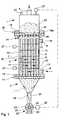
- FIG. 1 One in the Fig. 1 Overall illustrated apparatus for cooling and / or heating of bulk material has an upper buffer section 1, a middle heat exchange section 2 and a lower discharge section 3.
- the sections 1 to 3 each have a circular cross section.
- the housing-like, substantially enclosed buffer section 1 is provided with an upper inlet nozzle 4 for supplying a bulk material to be cooled or heated.
- the heat exchange section 2 has a housing 5, in the interior of which 6 are mutually parallel heat exchanger tubes 7 are arranged at a distance from each other, which extend substantially in the direction of gravity, which thus allow a promotion of bulk material under the influence of gravity.
- the interior 6 is therefore a heat exchange space.
- Typical inner diameters of the heat exchanger tubes 7 are 10 to 300 mm, preferably 15 to 170 mm.
- Adjacent to the discharge section 3 opens into the interior 6 of the housing 5 of the heat exchange section 2, a supply nozzle 8 for heat transfer fluid.
- the heat transfer fluid may be water, steam, a thermal oil or air.
- Adjacent to the buffer section 1 opens a discharge nozzle 9 from the interior 6 of the housing 5.
- deflection plates 10 are each transversely to the longitudinal direction of the tubes 7 at a distance from each other mounted such that a supplied via the supply nozzle 8 heat transfer fluid according to the flow direction arrow 11 meandering through the interior 6 each transverse to the longitudinal direction the heat exchanger tubes 7 gradually upward to the discharge nozzle 9 flows.
- the heat exchange section 2 is thus for a cross-countercurrent of the heat transfer fluid designed.
- the interior 6 can be filled with a tube 7 enveloping bed 12 of glass beads, steel balls and plastic granules, which contributes to the improvement of the heat transfer between the heat transfer fluid and the tubes 7.
- removable retaining sieves 13 are arranged in the socket 8, 9.
- the size of the particles of the bed 12 is such that they can be introduced after the preparation of the heat exchange section 2 in this.
- the particles of the bed 12 are thus smaller than the pitch of the tubes 7.
- the particles of the bed 12 are preferably spherical, lens or cylindrical shape.
- the heat exchanger tubes 7 are at the top in a fixedly connected to the housing 5 heat exchanger tube plate 14 (see. Fig. 2 ) and down with a spout tube bottom 15 connected so that they are open to the buffer section 1 and 3 to the discharge section. Between the buffer section 1 and the heat exchange section 2 on the one hand and the heat exchange section 2 and the discharge section 3 there are flange connections 16 and 17, respectively.
- the heat exchanger tubes 7 associated inlet pipes 14 b are arranged, which will be described below.
- the inlet tube bottom 14a is configured such that each inlet tube 14b has an inlet funnel 18 that widens toward the buffer section 1 and thus narrows towards the respective inlet tube 14b, wherein adjacent funnels 18 are dimensioned such that they are at the top in one to hit relatively sharp edge 19.
- the inlet tube bottom 14a can be designed to be vibrating with respect to the heat exchanger tube plate 14.
- an agitator can also be arranged in this.
- discharge aids may be appropriate for the bulk material such.
- the discharge section 3 is in the form of a downwardly tapered cone-shaped funnel. Such a shape causes the bulk material 20 flows in the discharge section 3 at all points of an arbitrarily selected cross section with almost the same speed, in this consideration, the immediate wall area does not take into account is because there is always a delay due to wall friction.
- a rotary valve 22 is provided, the housing 23 is connected via a downpipe 24 with the discharge section 3.
- the rotary valve 22 seals the discharge section 3 substantially fluid-tight.
- a cellular wheel 25 is arranged, which is rotatably driven by a motor 26.
- the motor 26 is driven by a level detector 27, which in turn detects the level of the bulk material 20 in the buffer section 1.
- a guide surface 28 is formed, which directs the bulk material 20 from the discharge section 3 to the revolving side of the rotational direction in the direction of rotation 29 driven cellular wheel 25.
- the directed over the guide surface 28 bulk flow is therefore already fully directed to a cell 30 of the cell wheel 25 when the cell 30 is opened during rotation in the direction of rotation 29 to the downpipe 24 out. This ensures a uniform withdrawal of the bulk material 20 over the entire inlet cross section of the rotary valve 22.
- essentially fluid-tight discharge organs can be used instead of the rotary valve 22.
- Such alternative dispensing devices are, for example, a double flap lock or a screw conveyor in which the product can be compacted to achieve a fluid seal.
- Another variant of a discharge is a long downpipe with an arranged metering slide. In this case, the bulk material can take over the substantially fluid-sealing effect in the downpipe.
- the upper ends of the heat exchanger tubes 7 are connected to one another via the heat exchanger tube plate 14.
- the Heat exchanger tubes 7 are fluid-tight welded to the heat exchanger tube plate 14.
- the heat exchanger tubes 7 may be soldered or rolled into the heat exchanger tube sheet 14.
- the inlet pipes 14b are interconnected.
- the inlet pipes 14b are inserted into corresponding openings in the inlet tube bottom 14a.
- the feed pipes 14b can be inserted in a fluid-tight manner into the inlet tube bottom 14a.
- the connection points between the inlet tubes 14b and the inlet tube plate 14a can be designed so that a certain gas passage through these joints is possible. Also a connection via a press fit is possible.
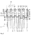
- the Fig. 2 shows three alternative possible variants of plug-in arrangements of the inlet pipes 14b in their associated heat exchanger tubes 7.
- the in the Fig. 2 On the left three connections shown with intermediate gap 31 extend the heat exchanger tubes 7 and the inlet tubes 14b in a cover section 32 straight.
- the overlap section 32 is a pipe section.
- a plug-in section 33 which is longer than the cover section 32, is present at the far right.
- a lower end 34 of the inlet tube 14b is widened conically in the cover section 33, so that a gap 35 present there between the inlet tube 14b and the heat exchanger tube 7 is reduced in relation to the other distance of the inlet tube 14b to the heat exchanger tube 7 in its width.
- second inlet pipe 14b from the right shows a further variant of a cover section 36.
- the latter is again extended compared to the covering section 33.
- a lower end 37 of the inlet pipe 14b is widened in the covering section 36 in at least one bulging section 38.
- a gap 39 between the inlet pipe 14b and the heat exchanger tube 7 in the region of the covering portion 36 with respect to the other distance between the two tubes 7, 14b in the covering pipe section 36 is reduced in its width.
- more than one such bulging portion 38 may be provided.
- the inlet tubes 14b have a smaller diameter than the heat exchanger tubes 7, so that the inlet tubes 14b are inserted into the cover sections 32, 33, 36 in the heat exchanger tubes 7.
- the gaps 31, 35, 39 have an average width in the range between 0 and 15 mm. Medium widths in the range 0 and 5 mm, between 0 and 3 mm and between 0 and 1 mm are preferred. The width is averaged around the circumference of the annular gaps 31, 35, 39.
- the covering sections 32, 33, 36 have a length between 1 and 1000 mm along the tubes 7, 14b, with lengths of the covering sections 32, 33, 36 between 10 and 500 mm, in particular between 50 and 500 mm, being preferred ,
- the gaps 31, 35, 39 form gas passage transitions.
- Gas can be supplied via the gas supply connecting piece 41 to a gap 43, which is bounded at the top by the inlet tube bottom 14a, is bounded at the bottom by the heat exchanger tube plate 14 and is bounded laterally by the inlet pipes 14b and the jacket wall 40.
- the gas is in particular air, which is preferably predried. Instead of air as a gas, for example, nitrogen, off-gas, so nitrogen with impurities such. As hydrocarbons, or carbon dioxide can be used.
- the gas may in particular in a preferably closed circuit, for. B. for processing, are performed.
- the longitudinal section of the Fig. 2 shown parts of the intermediate space 43 are all in fluid communication with each other around the inlet pipes 14b.
- the gas source 42 may be controlled to supply gas to the gap 43 via the gas supply port 41 in a pulsating manner.
- the lower ends of the supply pipes 14b communicate with the upper ends of the heat exchanger tubes 7.
- the passage formed by the gaps 31, 35, 39 is a passage of the gas supplied through the gas supply nozzle 41 from the gap 43 into the interior of the inlet pipes 14b possible.
- the path of the gas supplied from the gas source 42 to the gas supply port 41 is as follows: First, the gas from the gas supply port 41 enters the gap 43 and spreads there, so that all the supply pipes 14b of gas are surrounded to a good approximation to the same pressure. Then the gas flows, as in Fig. 2 illustrated by arrows 45, down and then, as illustrated by arrows 46, through the column 31 or, as in the other two embodiments, through the gaps 35 and 39.
- the gas flows after passing through the column 31 and 35, 39 upward through the inlet pipes 14b and the buffer section 1.
- the flowing through the bulk material 20 from the bottom up gas allows loosening and moisture in a drying of the bulk material 20.
- the now moist gas can the buffer section. 1 then leave via an exhaust port 47.
- the inlet tube bottom 14a is detachably connected to the heat exchanger tube plate 14 via a flange 48. In this way, the inlet tube bottom 14a can be removed together with the associated with this inlet pipes 14b from the heat exchanger tube plate 14 after loosening the flange 48.
- gas supply connection piece 41 instead of a single gas supply connection piece 41, it is also possible to provide a plurality of gas supply connection pieces which, for example, communicate with one another via a ring line which surrounds the outer wall 40 on the outside. For example, three or four circumferentially around the casing wall 40 equally distributed gas supply connection piece 41 may be provided. This reduces a gas pressure gradient in the gap 43 over the cross section of the inlet tube bottom 14a practically to zero.
- the intermediate space 43 can also be subdivided according to the number of the gas supply connection pieces, wherein each part space then communicates with one of the gas supply connection pieces.
- Each partial space then has a separate gas supply.
- a permanent gas flow based on the total cross section of the cooling and / or heating device with simultaneous pause times in individual segments be maintained.
- the gas admission of the partial spaces can be individually controlled, which extends the possibilities of controlling the gas flow in the inlet area.
- a subdivision of the intermediate space 43 into partial spaces facilitates a uniform gas distribution over the cross section of the cooling and / or heating device.
- partial spaces When individual gas is applied, individual partial spaces may be supplied with gas and others may not. This can be used for a targeted influencing of the flow behavior within the cooling and / or heating device over the cross section.
- the partial interstices, apart from supply line sections, may be substantially concentric with one another or may be shaped in the shape of a sector.
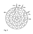
- Fig. 3 shows a concentric subdivision of the gap 43 into partial spaces 43a, 43b and 43c.
- the innermost part-space 43 a is assigned to a gas supply connection piece 41 a.
- the middle sub-space 43b is associated with a gas supply port 41b.
- the outer part-space 43c is associated with a gas supply port 41 c.
- Fig. 4 shows a sector-shaped subdivision of the gap 43 with four subspaces 43a to 43d covering the four quadrants of the circular cross-section of the device 1.
- the partial gap 43a encloses as the only partial gap the centrally along the central longitudinal axis extending inlet pipe 14b.
- the partial spaces 43a to 43d are associated with gas supply ports 41a to 41d.
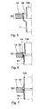
- Fig. 5 to 7 show further variants of constructive embodiments of the heat exchanger tubes 7 and the inlet tubes 14b in the region of the heat exchanger bottom 14th
- the heat exchanger tube 7 is expanded in the region of a cover portion 50.
- the axial extent of the cover portion 50 corresponds approximately to the thickness of the heat exchanger tube bottom 14th
- a gas passage transition is formed by a gap 51 at the level of the heat exchanger tube bottom 14.
- the heat exchanger tube plate 14 is used to realize an overlap and thus the gap 51 between the inlet tube 14b and the heat exchanger tube plate 14 in a cover section 52, in which the inlet tube 14b is inserted into the heat exchanger tube plate 14 .
- the heat exchanger tubes 7 are in the execution after Fig. 6 in the heat exchanger tube sheet 14 so welded that the upper ends of the heat exchanger tubes 7 are offset from their associated openings in the heat exchanger tube sheet 14 down. This offset makes it possible to insert the inlet pipe 14b assigned to the respective heat exchanger tube 7 from above into a receptacle of the heat exchanger tube bottom 14.
- the outer diameter of the inlet pipe 14b is smaller than the inner diameter of the associated receptacle in the heat exchanger tube plate 14, so that the gap 51 is formed.
- the mutually facing ends of the tubes 7, 14b are also spaced from each other in a defined manner, so that there is a gas passage transition between these ends.
- a further variant of the inlet pipe 14b is shown in dashed lines, whose outer diameter is greater than the inner diameter of the receptacle in the heat exchanger tube plate 14 for the heat exchanger tube 7.
- the lower end of the inlet tube 14b is defined by the top of the heat exchanger tube plate 14 facing it spaced so that a gap 53 is formed, which forms the gas passage transition in this variant.
- the heat exchanger tube plate 14 has a stepped receptacle 54 for the tubes 7, 14b. In an upper portion of the receptacle 54, this has an enlarged diameter, which is in particular greater than the outer diameter of the associated inlet pipe 14b, so that here a gap 55 between the inlet pipe 14b and the heat exchanger tube sheet 14 is formed.
- a gap 55 between the inlet pipe 14b and the heat exchanger tube sheet 14 is formed.
- Fig. 7 can be used for the heat exchanger tube 7 of the same type of tube with the same diameter dimensions as for the inlet pipe 14b.
- Inlet openings 55 of the inlet tube bottom 14a can be arranged on mutually concentric partial circles about a central center longitudinal axis of the housing 5.
- triangular arrangements, z. B. a 30 ° triangle arrangement of the inlet openings 55 of the inlet tube bottom 14 a are possible.
- Arrangements of the inlet openings 55 in a square or rectangular grid are also possible.
- the inlet tube bottom 14a may also consist of inlet-side end sections of the inlet tubes 14b which are hexagonally, triangularly, rectangularly or quadratically widened at their upper end and welded together.
- the inlet pipes 14b are widened hexagonally in each case in their upper end section 56. Adjacent upper edge portions 57 are welded together as shown in FIG Fig. 8 indicated by a weld.
- Fig. 10 shows accordingly in one too Fig. 8 a similar representation, a square arrangement of the inlet tubes 14b with end portions 56 and edge portions 57, which function in their corresponding components of the embodiment of the 8 and 9 correspond.
- Fig. 11 shows accordingly in one too Fig. 8 Similarly, a triangular arrangement of the inlet tubes 14b with end portions 56 and edge portions 57, which function in their corresponding components of the embodiment of the 8 and 9 correspond.
- the feed tubes 14b can be welded into the feed tube bottom 14a.
- the inlet pipes 14b may be glued, soldered, rolled or pressed into the inlet tube bottom 14a.
- the inlet tube bottom 14 a and the inlet tubes 14 b need not be made of steel, as is preferred for the heat exchanger tube plate 14 and the heat exchanger tubes 7.
- the inlet tube bottom 14a and the inlet tubes 14b may alternatively be made of plastic, aluminum or other non-ferrous metals.
- the inlet tube bottom 14a and the inlet tubes 14b of sintered materials such. As sintered metals or sintered plastics. This allows, in particular by the sintered material, a uniform gas supply and prevents caking of the bulk material 20th
- the inlet tubes 14b and the heat exchanger tubes 7 may be seamless tubes or also welded tubes.
- the amount of gas supplied via the gas source 42 to the feed pipes 14b and the overlying buffer section 1 is particularly high so that the bulk material 20 is fluidized over the cross section of the feed pipes 14b or in the inlet region of the feed pipes 14b, ie in the region of the feed openings 49 , The amount of gas can even be so high that the whole in Buffer section 1 located bulk material 20 is fluidized. Since the inlet pipes 14b have a smaller cross section than the heat exchanger pipes 7, the velocity of the gas through the inlet pipes 14b is increased.
- the amounts of gas fed in may lead to a gas velocity, based on the empty tube gas velocity in the feed tubes 14b or up to 20 times, more preferably up to 5 times, more preferably up to 5 times, based on the empty tube gas velocity in the buffer section 1 the minimum fluidization velocity of the bulk material 20. Due to the high gas velocity, in particular the formation of bulk material bridges in the region of the inlet openings 49 is prevented. This prevention is also the pulsating gas supply via the gas source 42. In the pulsation, the supplied amount of gas is varied. In particular, the supplied gas quantity can be interrupted intermittently, so that the intermediate space 43 is subjected to pressure surges. A continuous gas supply is possible.
- predrying the gas it can also be tempered in order to use the gas stream for cooling or for heating the bulk material 20 in the region of the feed pipes 14b or in the buffer section 1.
- a targeted pressure setting can be specified in the region of the inlet pipes 14b.
- gas which is supplied via the gas supply connection stub 41 is guided essentially completely through the inlet pipes 14b upwards and thus completely through the bulk material 20 in the buffer section 1.
Landscapes
- Engineering & Computer Science (AREA)
- Physics & Mathematics (AREA)
- Thermal Sciences (AREA)
- Mechanical Engineering (AREA)
- General Engineering & Computer Science (AREA)
- Heat-Exchange Devices With Radiators And Conduit Assemblies (AREA)
Applications Claiming Priority (1)
| Application Number | Priority Date | Filing Date | Title |
|---|---|---|---|
| DE102007015060A DE102007015060A1 (de) | 2007-03-26 | 2007-03-26 | Vorrichtung zum Kühlen und/oder Heizen von Schüttgut |
Publications (1)
| Publication Number | Publication Date |
|---|---|
| EP1975536A2 true EP1975536A2 (fr) | 2008-10-01 |
Family
ID=39632471
Family Applications (1)
| Application Number | Title | Priority Date | Filing Date |
|---|---|---|---|
| EP20080004260 Withdrawn EP1975536A2 (fr) | 2007-03-26 | 2008-03-07 | Dispositif pour refroidir et/ou chauffer une matière en vrac |
Country Status (2)
| Country | Link |
|---|---|
| EP (1) | EP1975536A2 (fr) |
| DE (1) | DE102007015060A1 (fr) |
Cited By (7)
| Publication number | Priority date | Publication date | Assignee | Title |
|---|---|---|---|---|
| EP2273221A3 (fr) * | 2009-07-08 | 2011-08-17 | Coperion GmbH | Dispositif de refroidissement de produits en vrac et procédé de traitement de produits en vrac |
| JP2013082892A (ja) * | 2011-09-30 | 2013-05-09 | Metawater Co Ltd | 炭化物の製造方法及び炭化物の製造システム |
| JP2013185116A (ja) * | 2012-03-09 | 2013-09-19 | Tsukishima Kikai Co Ltd | 固形物用熱交換器および有機性廃棄物の処理設備 |
| CN105066757A (zh) * | 2015-08-13 | 2015-11-18 | 北方民族大学 | 一种固体颗粒的空气蓄热放热装置 |
| CN112146352A (zh) * | 2020-09-29 | 2020-12-29 | 嘉施利(宁陵)化肥有限公司 | 复合肥生产用冷却机 |
| CN112871120A (zh) * | 2021-02-04 | 2021-06-01 | 中国特种设备检测研究院 | 一种高压反应釜 |
| CN117597562A (zh) * | 2021-06-08 | 2024-02-23 | 巴塞尔聚烯烃股份有限公司 | 用于气相聚合的热交换器 |
Families Citing this family (1)
| Publication number | Priority date | Publication date | Assignee | Title |
|---|---|---|---|---|
| DE102015013516B4 (de) * | 2015-10-20 | 2018-01-18 | Frank Brucker | Rohrbündelwärmeübertrager und Fertigungsverfahren für Rohrbündelwärmeübertrager |
Citations (1)
| Publication number | Priority date | Publication date | Assignee | Title |
|---|---|---|---|---|
| DE102004041375A1 (de) | 2004-03-24 | 2005-10-13 | Coperion Waeschle Gmbh & Co. Kg | Vorrichtung zum Temperieren von Schüttgut |
Family Cites Families (4)
| Publication number | Priority date | Publication date | Assignee | Title |
|---|---|---|---|---|
| GB501765A (en) * | 1936-09-05 | 1939-03-06 | Heinrich Koppers Ind Mij N V | Process and device for the supply and withdrawal of heat for granular material in chemical, especially catalytic furnaces and the like |
| US2417393A (en) * | 1942-11-04 | 1947-03-11 | Socony Vacuum Oil Co Inc | Apparatus for hydrocarbon reaction |
| US2458498A (en) * | 1946-08-31 | 1949-01-11 | Socony Vacuum Oil Co Inc | Method and apparatus for conversion of fluid hydrocarbons |
| US4307773A (en) * | 1978-08-28 | 1981-12-29 | Smith Richard D | Fluid bed heat exchanger for contaminated gas |
-
2007
- 2007-03-26 DE DE102007015060A patent/DE102007015060A1/de not_active Withdrawn
-
2008
- 2008-03-07 EP EP20080004260 patent/EP1975536A2/fr not_active Withdrawn
Patent Citations (1)
| Publication number | Priority date | Publication date | Assignee | Title |
|---|---|---|---|---|
| DE102004041375A1 (de) | 2004-03-24 | 2005-10-13 | Coperion Waeschle Gmbh & Co. Kg | Vorrichtung zum Temperieren von Schüttgut |
Cited By (8)
| Publication number | Priority date | Publication date | Assignee | Title |
|---|---|---|---|---|
| EP2273221A3 (fr) * | 2009-07-08 | 2011-08-17 | Coperion GmbH | Dispositif de refroidissement de produits en vrac et procédé de traitement de produits en vrac |
| JP2013082892A (ja) * | 2011-09-30 | 2013-05-09 | Metawater Co Ltd | 炭化物の製造方法及び炭化物の製造システム |
| JP2013185116A (ja) * | 2012-03-09 | 2013-09-19 | Tsukishima Kikai Co Ltd | 固形物用熱交換器および有機性廃棄物の処理設備 |
| CN105066757A (zh) * | 2015-08-13 | 2015-11-18 | 北方民族大学 | 一种固体颗粒的空气蓄热放热装置 |
| CN112146352A (zh) * | 2020-09-29 | 2020-12-29 | 嘉施利(宁陵)化肥有限公司 | 复合肥生产用冷却机 |
| CN112146352B (zh) * | 2020-09-29 | 2021-05-18 | 嘉施利(宁陵)化肥有限公司 | 复合肥生产用冷却机 |
| CN112871120A (zh) * | 2021-02-04 | 2021-06-01 | 中国特种设备检测研究院 | 一种高压反应釜 |
| CN117597562A (zh) * | 2021-06-08 | 2024-02-23 | 巴塞尔聚烯烃股份有限公司 | 用于气相聚合的热交换器 |
Also Published As
| Publication number | Publication date |
|---|---|
| DE102007015060A1 (de) | 2008-10-02 |
Similar Documents
| Publication | Publication Date | Title |
|---|---|---|
| EP1580511B1 (fr) | Dispositif pour maintenir la température de matière en vrac | |
| DE102007015060A1 (de) | Vorrichtung zum Kühlen und/oder Heizen von Schüttgut | |
| DE2012645A1 (de) | Vorrichtung zum Extrudieren von schwer extrudierbaren Materialien, insbesondere von Kunststoffabfällen | |
| DE102016007221B4 (de) | Drehrohrkühler und Verfahren zum Betreiben eines Drehrohrkühlers | |
| DE3144863C2 (de) | Wärmetauscher mit Fließbett | |
| DE69001804T2 (de) | Methode und vorrichtung zur kuehlung von festen teilchen. | |
| DE19648875B4 (de) | Fermenter für Biomasse | |
| EP2159526A2 (fr) | Installation de traitement pour produits en vrac | |
| DE2160962B2 (de) | Trommeltrockner zum Trocknen von Schlamm | |
| DE2634072B2 (de) | Trommeltrockner | |
| EP2468084A1 (fr) | Dispositif de dosage pour le dosage de semences | |
| DE2241264A1 (de) | Trockentrommel | |
| EP0087641A1 (fr) | Echantillonneur pour marchandises en vrac contenues dans un réservoir | |
| EP2273221B1 (fr) | Dispositif de refroidissement de produits en vrac et procédé de traitement de produits en vrac | |
| EP2006628B1 (fr) | Dispositif de refroidissement ou de chauffage de produits en vrac ainsi que procédé de fonctionnement d'un tel dispositif | |
| EP0089486B1 (fr) | Colonne à plusieurs enceintes fluidisées | |
| EP1288600B1 (fr) | Dispositif de séchage d'un matériau en vrac en contre-courant avec un fluide gazeux | |
| DE10138333A1 (de) | Vorrichtung zum Auspressen fließfähiger Substanzen | |
| AT403033B (de) | Materialschleuse für schüttgüter oder flüssigkeiten | |
| WO2017173473A1 (fr) | Vis sans fin à thermorégulation interne, installation et procédé de mise en oeuvre d'une telle vis sans fin | |
| DE3424841A1 (de) | Vorrichtung zur erzeugung einer gerichteten feststoffstroemung in wirbelschichten | |
| DE20010671U1 (de) | Wärmetauscher für rieselfähige Feststoffe | |
| DE102006002582B4 (de) | Fluidisiereinheit für einen Pulverförderer und Pulverförderer mit Fluidisiereinheit | |
| DE19709425C1 (de) | Vorrichtung zum Fluidisieren und Transportieren von feinkörnigen, pulverförmigen oder kurzfaserigen Materialien innerhalb eines Schlauches, Rohres oder Behälters | |
| DE60102677T2 (de) | Gefäss zum Ermöglichen von gleichmassigem Schwerkraftabfluss von Schüttgut und Direktreduktionsreaktor derselben enthaltend |
Legal Events
| Date | Code | Title | Description |
|---|---|---|---|
| PUAI | Public reference made under article 153(3) epc to a published international application that has entered the european phase |
Free format text: ORIGINAL CODE: 0009012 |
|
| AK | Designated contracting states |
Kind code of ref document: A2 Designated state(s): AT BE BG CH CY CZ DE DK EE ES FI FR GB GR HR HU IE IS IT LI LT LU LV MC MT NL NO PL PT RO SE SI SK TR |
|
| AX | Request for extension of the european patent |
Extension state: AL BA MK RS |
|
| RIN1 | Information on inventor provided before grant (corrected) |
Inventor name: ZECHNER, EGON Inventor name: DEHM, GUENTHER Inventor name: HUSTERT, OLAF Inventor name: DUERR, MICHAEL, DIPL.-ING. Inventor name: STARK, BERNHARD, DR. |
|
| RAP1 | Party data changed (applicant data changed or rights of an application transferred) |
Owner name: COPERION GMBH |
|
| STAA | Information on the status of an ep patent application or granted ep patent |
Free format text: STATUS: THE APPLICATION IS DEEMED TO BE WITHDRAWN |
|
| 18D | Application deemed to be withdrawn |
Effective date: 20101001 |