EP1976136A1 - Rake-Empfänger und Verfahren zur Anordnung der Finger in einem Rake-Empfänger - Google Patents
Rake-Empfänger und Verfahren zur Anordnung der Finger in einem Rake-Empfänger Download PDFInfo
- Publication number
- EP1976136A1 EP1976136A1 EP07105225A EP07105225A EP1976136A1 EP 1976136 A1 EP1976136 A1 EP 1976136A1 EP 07105225 A EP07105225 A EP 07105225A EP 07105225 A EP07105225 A EP 07105225A EP 1976136 A1 EP1976136 A1 EP 1976136A1
- Authority
- EP
- European Patent Office
- Prior art keywords
- delay
- antenna
- fingers
- rake receiver
- threshold
- Prior art date
- Legal status (The legal status is an assumption and is not a legal conclusion. Google has not performed a legal analysis and makes no representation as to the accuracy of the status listed.)
- Withdrawn
Links
- 238000000034 method Methods 0.000 title claims description 35
- 230000001934 delay Effects 0.000 claims description 14
- 239000006185 dispersion Substances 0.000 claims 10
- 238000010295 mobile communication Methods 0.000 claims 1
- 238000005562 fading Methods 0.000 description 10
- 230000008569 process Effects 0.000 description 10
- 230000000875 corresponding effect Effects 0.000 description 6
- 238000013461 design Methods 0.000 description 5
- 230000006735 deficit Effects 0.000 description 4
- 238000013459 approach Methods 0.000 description 3
- 230000015556 catabolic process Effects 0.000 description 3
- 230000008859 change Effects 0.000 description 3
- 230000002596 correlated effect Effects 0.000 description 3
- 238000006731 degradation reaction Methods 0.000 description 3
- 230000008878 coupling Effects 0.000 description 2
- 238000010168 coupling process Methods 0.000 description 2
- 238000005859 coupling reaction Methods 0.000 description 2
- 230000007246 mechanism Effects 0.000 description 2
- 230000008901 benefit Effects 0.000 description 1
- 230000005540 biological transmission Effects 0.000 description 1
- 230000001010 compromised effect Effects 0.000 description 1
- 230000003111 delayed effect Effects 0.000 description 1
- 230000001419 dependent effect Effects 0.000 description 1
- 238000010586 diagram Methods 0.000 description 1
- 230000000694 effects Effects 0.000 description 1
- 230000003993 interaction Effects 0.000 description 1
- 230000007774 longterm Effects 0.000 description 1
- 238000005259 measurement Methods 0.000 description 1
- 230000000116 mitigating effect Effects 0.000 description 1
- 238000012545 processing Methods 0.000 description 1
- 230000004044 response Effects 0.000 description 1
- 230000035945 sensitivity Effects 0.000 description 1
- 230000007480 spreading Effects 0.000 description 1
Images


Classifications
-
- H—ELECTRICITY
- H04—ELECTRIC COMMUNICATION TECHNIQUE
- H04B—TRANSMISSION
- H04B1/00—Details of transmission systems, not covered by a single one of groups H04B3/00 - H04B13/00; Details of transmission systems not characterised by the medium used for transmission
- H04B1/69—Spread spectrum techniques
- H04B1/707—Spread spectrum techniques using direct sequence modulation
- H04B1/7097—Interference-related aspects
- H04B1/711—Interference-related aspects the interference being multi-path interference
- H04B1/7115—Constructive combining of multi-path signals, i.e. RAKE receivers
- H04B1/7117—Selection, re-selection, allocation or re-allocation of paths to fingers, e.g. timing offset control of allocated fingers
-
- H—ELECTRICITY
- H04—ELECTRIC COMMUNICATION TECHNIQUE
- H04B—TRANSMISSION
- H04B7/00—Radio transmission systems, i.e. using radiation field
- H04B7/02—Diversity systems; Multi-antenna system, i.e. transmission or reception using multiple antennas
- H04B7/04—Diversity systems; Multi-antenna system, i.e. transmission or reception using multiple antennas using two or more spaced independent antennas
- H04B7/08—Diversity systems; Multi-antenna system, i.e. transmission or reception using multiple antennas using two or more spaced independent antennas at the receiving station
- H04B7/0837—Diversity systems; Multi-antenna system, i.e. transmission or reception using multiple antennas using two or more spaced independent antennas at the receiving station using pre-detection combining
- H04B7/0842—Weighted combining
- H04B7/086—Weighted combining using weights depending on external parameters, e.g. direction of arrival [DOA], predetermined weights or beamforming
-
- H—ELECTRICITY
- H04—ELECTRIC COMMUNICATION TECHNIQUE
- H04B—TRANSMISSION
- H04B7/00—Radio transmission systems, i.e. using radiation field
- H04B7/02—Diversity systems; Multi-antenna system, i.e. transmission or reception using multiple antennas
- H04B7/04—Diversity systems; Multi-antenna system, i.e. transmission or reception using multiple antennas using two or more spaced independent antennas
- H04B7/08—Diversity systems; Multi-antenna system, i.e. transmission or reception using multiple antennas using two or more spaced independent antennas at the receiving station
- H04B7/0891—Space-time diversity
- H04B7/0897—Space-time diversity using beamforming per multi-path, e.g. to cope with different directions of arrival [DOA] at different multi-paths
Definitions
- the present invention relates to a RAKE receiver and a method for allocating a number of despreading fingers in a RAKE receiver, which is adapted to receive input from at least a first and a second antenna, to a number of delay positions of a signal transmitted over a channel.
- the physical channel between the transmitter and the receiver is formed by a radio link.
- CDMA Code Division Multiple Access
- a RAKE receiver includes various 'fingers', or despreaders, each finger having an assigned path delay for receiving a particular image of a multipath signal and a correlator for despreading the received image.
- the fingers despread multiple signal images of a received multipath signal, thus mitigating the effect of the multipath channel fading phenomenon.
- each multipath component is assigned a finger, or despreader, whose reference copy of the spreading code is delayed equally to the path delay of the corresponding multipath component.
- the outputs of the RAKE fingers are coherently combined to produce a symbol estimate.
- the RAKE receiver requires knowledge of the multipath delays and the values of the channel impulse response for all paths. The best performance is achieved if the signal energy from all paths is utilized.
- the combining of the outputs performed by the RAKE receiver improves the signal-to-noise ratio (SNR) since it allows the desired signal components to be summed coherently, while the interference and noise components are summed non-coherently.
- SNR signal-to-noise ratio
- the combining is made by a Maximal-Ratio Combining (MRC) procedure, wherein the different signal components are weighted according to their respective SNR.
- MRC Maximal-Ratio Combining
- One such advanced receiver type is the dual-antenna receiver, where the signal is received via two separate antennas, RF (Radio Frequency) and front end processing branches. If the two branches are sufficiently separated (electrically and spatially), the fading processes and the noise and interference signal components on the two branches, as seen by the RAKE receiver, will be substantially uncorrelated.
- RF Radio Frequency
- the dual-antenna RAKE receiver (RAKE2) will then exhibit improved performance, due to the array gain (more signal energy is received) and the diversity gain (reduced probability of deep fades). As a result, the Block Error Rate (BLER) performance of the receiver will be improved.
- RAKE2 The dual-antenna RAKE receiver
- the finger placement is the same as in a single-antenna receiver.
- the RAKE2 fingers are placed on the strongest paths, without regard to which antenna branch they belong to. For a well-separated multi-branch architecture, this would be the best way of utilizing the available diversity and array gain.
- cross-talk may occur due to spatial limitations, i.e. that the two receiver antennas may not be sufficiently separated due to terminal size constraints.
- electrical coupling may occur when the circuits and conducting surfaces in the mechanical design of the terminal introduce coupling between the signal paths of the receiver branches.
- the impairment components on the two fingers are correlated, they accumulate coherently, together with the signal component, which in turn means that the array gain is compromised.
- Embodiments of the present invention recognize the fact that the indiscriminate RAKE2 finger placement with up to two fingers per delay may lead to performance degradation, and that it therefore is desirable to find an approach to diversity RAKE combining which accounts for the qualitative change in behavior at high antenna correlations.
- Embodiments of the invention alleviate the above mentioned problems by providing a finger placement strategy which adapts to the situation at hand, while not requiring considerable additional complexity in the receiver.
- a RAKE receiver which is adapted to receive input from at least a first and a second antenna, comprises
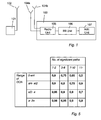
- a transmitter 101 is shown, which, via a transmitter antenna 102, transmits a signal.
- a receiver 103 receives the signal via two receiver antennas 104a and 104b.
- the signals received by the first and the second antenna are first processed in a radio processor or unit 105, then in a baseband processor or unit 106 and then in some additional processor or unit 107.
- the method according to embodiments of the invention takes place in the baseband unit.
- Embodiments of the present invention relates to a multiple antenna RAKE receiver for CDMA where the receive antenna correlation may assume high values.
- the receive antenna correlation may assume high values.
- a dual-antenna embodiment is described but the extension to a multiple antenna receiver would from this disclosure be obvious for a skilled person.
- the radio unit 105 is connected to a channel estimation unit 301, a path searcher 302 and a RAKE despreader or despreading unit 303.
- the RAKE despreader 303 is connected to a RAKE combiner or combining unit 304.
- the path searcher 302 is connected to the channel estimation unit and to a delay position selection unit 305.
- the channel estimation unit 301 is also connected to the delay position selection unit 305, which in turn is connected to the RAKE despreader 303.
- the path searcher 302 processes the received output from the radio unit to find a Power Delay Profile (PDP) and extract relevant paths, in a manner known to a skilled person.
- PDP Power Delay Profile
- the channel estimation unit 301 produces channel estimates also in a known manner. The channel estimates are input to the combiner 304 together with the despread data from the despreading unit.
- data from the path searcher 302 and the channel estimation unit 301 are processed in order to select a strategy for placing or allocating a number N f of despreading fingers in the despreading unit 303 on a number of delay positions that are received from the two antennas 104a and 104b through the radio unit 105.
- the despreading unit then despreads, in a known manner, the data from the radio unit 105 corresponding to the delay positions chosen by the delay position selection unit 305.
- the delay positions may be illustrated as in Fig 4 .
- the delay positions d11, d12 and d13 might have been received from the first antenna 104a and the delay positions d21, d22 and d23 from the second antenna 104b.
- the total number of delay positions equals six. If, for instance, the number of despreading fingers N f equals three, the receiver will have to choose three of the six delay positions for placing the fingers.
- the current reception conditions are taken into account when choosing which delay positions to use when only a limited number of fingers are available for despreading.
- a finger allocating strategy is applied that is optimal for the conditions.
- the RAKE fingers should be placed on the paths with largest magnitude, regardless of which receiver antenna they correspond to, or whether one or several fingers are placed on the same delay on different antennas. This may be referred to as an unconstrained placement strategy. For "high” correlation", only one finger per delay should be allowed selecting the antenna with instantaneously higher path magnitude, if possible. This may be denoted as constrained placement.
- the delays d11, d21 and d23 would be chosen.
- the delays d21, d12 and d23 would be chosen.
- the receiver might, for certain reasons, in the case of "high” antenna correlation, choose delays from one antenna only. Then the delays belonging to the - in some sense - strongest, or first, antenna are chosen.
- the strongest antenna may be defined e.g. as the antenna providing the highest average received SNR or sensitivity.
- the appropriate threshold between "low” and “high” correlation is situation-dependent. Factors that lower the threshold are e.g. few available RAKE fingers, strongly dispersive channels, and a narrow range of direction of arrivals. All these parameters, as well as the effective signal correlation value, are available at the receiver or may be estimated.
- One possible way to implement the method is in the form of a pre-computed table look-up, where the number of the available RAKE fingers determines the table, the number of significant paths in the channel realization the column, and the range of directions of arrival the row. The table entry then provides the threshold value with which the current estimated correlation value is compared, and the appropriate finger placement strategy is applied.
- the number of significant paths is determined using the Power Delay Profile (PDP) of the channel, preferably with a 1-chip resolution. This shows the number of paths that strongly contribute to the dispersiveness. To that end, the number of peaks that significantly exceed the noise floor (e.g. their power is at least 10 times that of the noise floor) may be counted.
- the path searcher 302 may be configured to report the number of paths and this may be taken as a simple measure of the richness of the channel.
- DOA range of direction of arrivals
- , max ⁇ ⁇ ⁇ n ⁇ ⁇ n - min ⁇ ⁇ ⁇ n ⁇ ⁇ n , with ⁇ ' n mod( ⁇ n + ⁇ , 2 ⁇ ), where only the paths with a non-negligible correlation magnitude are taken into account,
- the threshold is chosen empirically, e.g.
- ⁇ 0.1 ⁇ max (
- the measurement period K may be chosen long (e.g. the order of several seconds). For the same reason, "block sums over K" may be stored for the purpose of updating the moving average process, to avoid storing all correlation products over K slots.
- step 205 the threshold value ⁇ is determined in step 206 and the estimated correlation ⁇ is compared to the threshold value ⁇ in step 207. If the correlation ⁇ is smaller than the threshold value ⁇ , the NO path is taken and a first, or unconstrained, placement strategy is applied in step 208. If the correlation ⁇ is larger than the threshold value ⁇ , the YES path is taken and a second, or constrained, placement strategy is instead applied in step 209.
- N f 6 RAKE fingers being available and the chosen table could look like that depicted in Fig. 5 .
- the threshold values for the table entries may be pre-determined off-line, e.g. based on simulated or measured RAKE performance in the relevant scenarios, using the candidate finger placement approaches.
- the process of selecting an appropriate strategy needs to be executed relatively seldom, e.g. the order of once a few seconds.
- the correlation threshold values in Fig 5 are merely examples, and should not be interpreted as exact values for an implementation. Also, the chosen ranges of DOA and numbers of paths are only exemplary. The structure of the tables may also be changed without changing the spirit of the invention. Different quantities may of course be used to label the tables, rows, and columns, and additional parameters may be added, without deviating from the fundamental idea of the invention.
- the constrained and unconstrained finger placement strategies may be applied to both instantaneous channel magnitude-based and average PDP-based placement processes.
- the channel estimates for all delay position on both antennas are first computed. Then, for the unconstrained placement option, the delay positions are sorted in a descending order according to their channel estimate magnitudes, irrespective of which antenna they belong to. The N f largest magnitudes are then selected and the fingers are placed on the corresponding delay positions and antennas.
- the delay positions are first reviewed and if, for some delay position, there are corresponding delay positions on both antennas, then the delay position with the lower instantaneous channel estimate magnitude is removed from the list. The remaining delay positions are then sorted and the fingers are placed on the N f largest remaining delay positions.
- the finger placement may be based on the long-term average path strengths.
- the delay positions are instead sorted by the average signal strength.
- the average signal strength is the same for two delay positions on different antennas that correspond to the same input path.
- the N f delays having the strongest average signal strengths are selected and the fingers are placed on these delays. Since the average signal strength is the same for pairs of delay positions, this option could also be described as: the delays corresponding to the N f / 2 strongest average signal strengths are selected, and the RAKE2 fingers are placed these delays on both antennas.
- the candidate delays are sorted by the average signal strength in the same way.
- the N f strongest are selected, and the RAKE2 fingers are placed on those delays on one of the antennas, e.g. the strongest one.
- the strongest antenna may be known by design or may be determined e.g. by comparing the actual Signal to Noise Ratio (SNR) values per antenna that are measured as part of standard User Equipment (UE) procedures.
- SNR Signal to Noise Ratio
- the correlation threshold values may depend on whether the instantaneous, i.e. the current channel estimates, or average path strengths are used as placement criteria.
Landscapes
- Engineering & Computer Science (AREA)
- Computer Networks & Wireless Communication (AREA)
- Signal Processing (AREA)
- Radio Transmission System (AREA)
- Mobile Radio Communication Systems (AREA)
Priority Applications (3)
| Application Number | Priority Date | Filing Date | Title |
|---|---|---|---|
| EP07105225A EP1976136A1 (de) | 2007-03-29 | 2007-03-29 | Rake-Empfänger und Verfahren zur Anordnung der Finger in einem Rake-Empfänger |
| PCT/EP2008/052331 WO2008119603A1 (en) | 2007-03-29 | 2008-02-27 | A rake receiver and a method of allocating fingers in a rake receiver |
| US12/529,185 US8565706B2 (en) | 2007-03-29 | 2008-02-27 | Rake receiver and a method of allocating fingers in a RAKE receiver |
Applications Claiming Priority (1)
| Application Number | Priority Date | Filing Date | Title |
|---|---|---|---|
| EP07105225A EP1976136A1 (de) | 2007-03-29 | 2007-03-29 | Rake-Empfänger und Verfahren zur Anordnung der Finger in einem Rake-Empfänger |
Publications (1)
| Publication Number | Publication Date |
|---|---|
| EP1976136A1 true EP1976136A1 (de) | 2008-10-01 |
Family
ID=38330190
Family Applications (1)
| Application Number | Title | Priority Date | Filing Date |
|---|---|---|---|
| EP07105225A Withdrawn EP1976136A1 (de) | 2007-03-29 | 2007-03-29 | Rake-Empfänger und Verfahren zur Anordnung der Finger in einem Rake-Empfänger |
Country Status (3)
| Country | Link |
|---|---|
| US (1) | US8565706B2 (de) |
| EP (1) | EP1976136A1 (de) |
| WO (1) | WO2008119603A1 (de) |
Families Citing this family (2)
| Publication number | Priority date | Publication date | Assignee | Title |
|---|---|---|---|---|
| US8565685B2 (en) * | 2011-01-28 | 2013-10-22 | Nokia Corporation | Utilization-based threshold for choosing dynamically between eager and lazy scheduling strategies in RF resource allocation |
| WO2023085848A1 (ko) * | 2021-11-12 | 2023-05-19 | 삼성전자 주식회사 | 신호 제어 방법 및 이를 지원하는 웨어러블 장치 |
Citations (3)
| Publication number | Priority date | Publication date | Assignee | Title |
|---|---|---|---|---|
| US20030210670A1 (en) * | 2002-05-07 | 2003-11-13 | Matsushita Electric Industrial Co., Ltd. | Radio communication device and arrival direction estimation method |
| US20060203894A1 (en) * | 2005-03-10 | 2006-09-14 | Nokia Corporation | Method and device for impulse response measurement |
| US20060256842A1 (en) | 2003-05-21 | 2006-11-16 | Nec Corporation | Reception device and radio communication system using the same |
Family Cites Families (8)
| Publication number | Priority date | Publication date | Assignee | Title |
|---|---|---|---|---|
| US7085310B2 (en) * | 2001-01-29 | 2006-08-01 | Qualcomm, Incorporated | Method and apparatus for managing finger resources in a communication system |
| JP3880437B2 (ja) * | 2001-08-31 | 2007-02-14 | 松下電器産業株式会社 | 送受信装置及び送受信方法 |
| US7239677B2 (en) * | 2003-04-29 | 2007-07-03 | Telefonaktiebolaget L M Ericsson (Publ) | Method and apparatus for soft symbol scaling |
| US7116998B2 (en) * | 2003-05-14 | 2006-10-03 | Telefonaktiebolaget L M Ericsson (Publ) | Subtractive multipath delay detection |
| US7469024B2 (en) * | 2003-09-02 | 2008-12-23 | Telefonaktiebolaget Lm Ericsson (Publ) | Method and apparatus for finger placement in rake receiver |
| JP4389704B2 (ja) * | 2004-07-16 | 2009-12-24 | 日本電気株式会社 | Cdma受信装置、およびcdma受信装置における同期タイミング検出方法 |
| US7508863B2 (en) * | 2004-12-13 | 2009-03-24 | Alcatel-Lucent Usa Inc. | Method of processing multi-path signals |
| US7680176B2 (en) * | 2005-11-21 | 2010-03-16 | Telefonaktiebolaget Lm Ericsson (Publ) | Simplified generalized rake receiver method and apparatus |
-
2007
- 2007-03-29 EP EP07105225A patent/EP1976136A1/de not_active Withdrawn
-
2008
- 2008-02-27 WO PCT/EP2008/052331 patent/WO2008119603A1/en not_active Ceased
- 2008-02-27 US US12/529,185 patent/US8565706B2/en not_active Expired - Fee Related
Patent Citations (3)
| Publication number | Priority date | Publication date | Assignee | Title |
|---|---|---|---|---|
| US20030210670A1 (en) * | 2002-05-07 | 2003-11-13 | Matsushita Electric Industrial Co., Ltd. | Radio communication device and arrival direction estimation method |
| US20060256842A1 (en) | 2003-05-21 | 2006-11-16 | Nec Corporation | Reception device and radio communication system using the same |
| US20060203894A1 (en) * | 2005-03-10 | 2006-09-14 | Nokia Corporation | Method and device for impulse response measurement |
Non-Patent Citations (2)
| Title |
|---|
| FUJII ET AL.: "Rake received characteristics considering antenna diversity and path diversity for wideband DC-CDMA system", ELECTRONICS & COMMUNICATIONS IN JAPAN, vol. 84, no. 10, 2001, pages 36 - 54, XP001065737, DOI: doi:10.1002/ecja.1046.abs |
| FUJII T ET AL: "RAKE RECEIVED CHARACTERISTICS CONSIDERING ANTENNA DIVERSITY AND PATH DIVERSITY FOR WIDEBAND DS-CDMA SYSTEM", ELECTRONICS & COMMUNICATIONS IN JAPAN, PART I - COMMUNICATIONS, WILEY, HOBOKEN, NJ, US, vol. 84, no. 10, PART 1, 2001, pages 36 - 54, XP001065737, ISSN: 8756-6621 * |
Also Published As
| Publication number | Publication date |
|---|---|
| US8565706B2 (en) | 2013-10-22 |
| WO2008119603A1 (en) | 2008-10-09 |
| US20100081403A1 (en) | 2010-04-01 |
Similar Documents
| Publication | Publication Date | Title |
|---|---|---|
| EP1858175B1 (de) | Verfahren und geräte zum realisieren einer intelligenten antenne in einem wcdma-system | |
| KR101256695B1 (ko) | 일반화된 레이크 수신을 통한 적응형 타이밍 회복 | |
| US6385181B1 (en) | Array antenna system of wireless base station | |
| US20040048593A1 (en) | Adaptive antenna receiver | |
| JP3619729B2 (ja) | 無線受信装置および無線受信方法 | |
| US7006042B2 (en) | Antenna array system, method of controlling the directivity pattern thereof, and mobile terminal | |
| EP1365521B1 (de) | Wegzeitdetektionsverfahren in einem adaptiven Gruppenantennensystem | |
| JP2011524124A (ja) | 無線受信器における干渉の効率的推定のための方法と装置 | |
| US8335273B2 (en) | Control apparatus for and control method of equalizer, and wireless terminal having that control apparatus | |
| EP2012439B1 (de) | Empfänger und Empfangsverarbeitungsverfahren | |
| KR100818465B1 (ko) | 다중 수신기 안테나용 레이크 기반 cdma 수신기 | |
| US7535970B2 (en) | Wireless communication apparatus and method for multiple transmit and receive antenna system using multiple codes | |
| US6983172B2 (en) | Method and apparatus for transmitting a traffic signal using an adaptive antenna array | |
| US8565706B2 (en) | Rake receiver and a method of allocating fingers in a RAKE receiver | |
| US7978751B2 (en) | Interpolating GRAKE with two step delay hypothesis testing | |
| EP2119157B1 (de) | Interferenzvarianzkalkulation für signalerfassung | |
| US20030130012A1 (en) | Method and device for evaluating an uplink radio signal | |
| EP1511187A2 (de) | Sendeleistungsregelung für ein Mehrkodemehrantennensystem | |
| HK1120945A (en) | Adaptive timing recovery via generalized rake conception |
Legal Events
| Date | Code | Title | Description |
|---|---|---|---|
| PUAI | Public reference made under article 153(3) epc to a published international application that has entered the european phase |
Free format text: ORIGINAL CODE: 0009012 |
|
| AK | Designated contracting states |
Kind code of ref document: A1 Designated state(s): AT BE BG CH CY CZ DE DK EE ES FI FR GB GR HU IE IS IT LI LT LU LV MC MT NL PL PT RO SE SI SK TR |
|
| AX | Request for extension of the european patent |
Extension state: AL BA HR MK RS |
|
| 17P | Request for examination filed |
Effective date: 20081020 |
|
| 17Q | First examination report despatched |
Effective date: 20081120 |
|
| AKX | Designation fees paid |
Designated state(s): AT BE BG CH CY CZ DE DK EE ES FI FR GB GR HU IE IS IT LI LT LU LV MC MT NL PL PT RO SE SI SK TR |
|
| GRAP | Despatch of communication of intention to grant a patent |
Free format text: ORIGINAL CODE: EPIDOSNIGR1 |
|
| INTG | Intention to grant announced |
Effective date: 20160314 |
|
| STAA | Information on the status of an ep patent application or granted ep patent |
Free format text: STATUS: THE APPLICATION IS DEEMED TO BE WITHDRAWN |
|
| 18D | Application deemed to be withdrawn |
Effective date: 20160726 |