EP1976149B1 - Procédé et dispositif pour transmettre des signaux dans un système de communication sans fil, dispositif de réception et procédé pour la réception de signaux dans un système de communication sans fil - Google Patents
Procédé et dispositif pour transmettre des signaux dans un système de communication sans fil, dispositif de réception et procédé pour la réception de signaux dans un système de communication sans fil Download PDFInfo
- Publication number
- EP1976149B1 EP1976149B1 EP07105275A EP07105275A EP1976149B1 EP 1976149 B1 EP1976149 B1 EP 1976149B1 EP 07105275 A EP07105275 A EP 07105275A EP 07105275 A EP07105275 A EP 07105275A EP 1976149 B1 EP1976149 B1 EP 1976149B1
- Authority
- EP
- European Patent Office
- Prior art keywords
- path
- frames
- beacon
- frame
- narrow beam
- Prior art date
- Legal status (The legal status is an assumption and is not a legal conclusion. Google has not performed a legal analysis and makes no representation as to the accuracy of the status listed.)
- Not-in-force
Links
Images




Classifications
-
- H—ELECTRICITY
- H04—ELECTRIC COMMUNICATION TECHNIQUE
- H04B—TRANSMISSION
- H04B7/00—Radio transmission systems, i.e. using radiation field
- H04B7/02—Diversity systems; Multi-antenna system, i.e. transmission or reception using multiple antennas
- H04B7/04—Diversity systems; Multi-antenna system, i.e. transmission or reception using multiple antennas using two or more spaced independent antennas
- H04B7/0408—Diversity systems; Multi-antenna system, i.e. transmission or reception using multiple antennas using two or more spaced independent antennas using two or more beams, i.e. beam diversity
-
- H—ELECTRICITY
- H01—ELECTRIC ELEMENTS
- H01Q—ANTENNAS, i.e. RADIO AERIALS
- H01Q1/00—Details of, or arrangements associated with, antennas
- H01Q1/12—Supports; Mounting means
- H01Q1/22—Supports; Mounting means by structural association with other equipment or articles
- H01Q1/24—Supports; Mounting means by structural association with other equipment or articles with receiving set
- H01Q1/241—Supports; Mounting means by structural association with other equipment or articles with receiving set used in mobile communications, e.g. GSM
- H01Q1/246—Supports; Mounting means by structural association with other equipment or articles with receiving set used in mobile communications, e.g. GSM specially adapted for base stations
-
- H—ELECTRICITY
- H04—ELECTRIC COMMUNICATION TECHNIQUE
- H04B—TRANSMISSION
- H04B7/00—Radio transmission systems, i.e. using radiation field
- H04B7/02—Diversity systems; Multi-antenna system, i.e. transmission or reception using multiple antennas
- H04B7/04—Diversity systems; Multi-antenna system, i.e. transmission or reception using multiple antennas using two or more spaced independent antennas
- H04B7/06—Diversity systems; Multi-antenna system, i.e. transmission or reception using multiple antennas using two or more spaced independent antennas at the transmitting station
- H04B7/0686—Hybrid systems, i.e. switching and simultaneous transmission
- H04B7/0695—Hybrid systems, i.e. switching and simultaneous transmission using beam selection
-
- H—ELECTRICITY
- H04—ELECTRIC COMMUNICATION TECHNIQUE
- H04B—TRANSMISSION
- H04B7/00—Radio transmission systems, i.e. using radiation field
- H04B7/02—Diversity systems; Multi-antenna system, i.e. transmission or reception using multiple antennas
- H04B7/04—Diversity systems; Multi-antenna system, i.e. transmission or reception using multiple antennas using two or more spaced independent antennas
- H04B7/08—Diversity systems; Multi-antenna system, i.e. transmission or reception using multiple antennas using two or more spaced independent antennas at the receiving station
- H04B7/0868—Hybrid systems, i.e. switching and combining
- H04B7/088—Hybrid systems, i.e. switching and combining using beam selection
-
- H—ELECTRICITY
- H04—ELECTRIC COMMUNICATION TECHNIQUE
- H04L—TRANSMISSION OF DIGITAL INFORMATION, e.g. TELEGRAPHIC COMMUNICATION
- H04L1/00—Arrangements for detecting or preventing errors in the information received
- H04L1/0001—Systems modifying transmission characteristics according to link quality, e.g. power backoff
- H04L1/0006—Systems modifying transmission characteristics according to link quality, e.g. power backoff by adapting the transmission format
-
- H—ELECTRICITY
- H04—ELECTRIC COMMUNICATION TECHNIQUE
- H04L—TRANSMISSION OF DIGITAL INFORMATION, e.g. TELEGRAPHIC COMMUNICATION
- H04L1/00—Arrangements for detecting or preventing errors in the information received
- H04L1/02—Arrangements for detecting or preventing errors in the information received by diversity reception
- H04L1/06—Arrangements for detecting or preventing errors in the information received by diversity reception using space diversity
-
- H—ELECTRICITY
- H04—ELECTRIC COMMUNICATION TECHNIQUE
- H04L—TRANSMISSION OF DIGITAL INFORMATION, e.g. TELEGRAPHIC COMMUNICATION
- H04L5/00—Arrangements affording multiple use of the transmission path
- H04L5/003—Arrangements for allocating sub-channels of the transmission path
-
- H—ELECTRICITY
- H04—ELECTRIC COMMUNICATION TECHNIQUE
- H04W—WIRELESS COMMUNICATION NETWORKS
- H04W48/00—Access restriction; Network selection; Access point selection
- H04W48/08—Access restriction or access information delivery, e.g. discovery data delivery
Definitions
- the present invention relates to a transmitting device for transmitting signals in a wireless communication system, to a receiving device for receiving signals in a wireless communication system, to a method for transmitting signals in a wireless communication system as well as to a method for receiving signals in a wireless communication system.
- Wireless communication is used in a large variety of technical fields, such as mobile telephones, wireless LAN, broadcast radio systems, point-to-point radio systems and many other known and future applications.
- the communication radius covered by a respective wireless communication system basically depends on the technique used. Whereas cellular communication systems, such as the GSM and the UMTS system, are adapted for a communication radius up to about 10 km (or more), wireless LAN is in the range of about 100 m (or more) and the Bluetooth system is in the range of several 10 m (or more).
- the mayor influences on the communication range of a wireless communication system are the radio frequency and the output power used.
- LOS direct line of sight
- reflection paths between the transmitter and the receiver, i. e. transmission paths in which the transmitted electromagnetic wave is reflected at least once by objects before it reaches the receiver.
- the transmitter In the state of art therefore for the transmitter, the receiver or for both several narrow beam antennas are used.
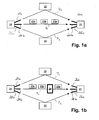
- An example for such a communication system is shown in Fig. 1 a.
- the shown communication system comprises a transmitter 20 and a receiver 21.
- the transmitter comprises three narrow beam antennas 25a, 25b and 25c and the receiver 21 as well comprises three narrow beam antennas 26a, 26b and 26c.
- the transmitter 20 or the receiver 21 comprises a single wide beam antenna.
- Fig. 1 a The shown communication system comprises a transmitter 20 and a receiver 21.
- the transmitter comprises three narrow beam antennas 25a, 25b and 25c and the receiver 21 as well comprises three narrow beam antennas 26a, 26b and 26c.
- the transmitter 20 or the receiver 21 comprises a single wide beam antenna.
- a first transmission path P 0 is the line of sight path and two other paths P 1 and P 2 are none line of sight paths, in which the transmitted electromagnetic wave is reflected by objects 22.
- the communication then is started over the transmission path having the best transmission characteristics.
- the direct line of sight path P 0 has the best characteristics and therefore the data frames 23a, 23b and 23c are transmitted over this path.
- the communication goes then on over the selected path until due to any reason, e. g. a moving human being, a vehicle or the like, the actual used transmission path gets blocked. In this case, the communication is then switched to a further path, for example to path P 1 .
- the problem that arises with the shown state of the art communication system is shown in Fig. 1b .
- the shown communication system again comprises a transmitter 20 and a receiver 21 each having several narrow beam antennas 25a, 25b, 25c, 26a, 26b and 26c.
- the communication is started with the transmission of the first data frame 23a via the active path P 0 .
- an obstacle 24 blocks the actual transmission path P 0 at least some of the further data frames 23b, 23c will get blocked by the obstacle and will not arive at the receiver 21.
- the communication will then switch to another path P 1 or P 2 .
- WO 20061031495 A2 discloses a method and system for establishing association between a station and an access point in a wireless local area network. For this purpose a beacon frame is transmitted by the access point on one antenna beam.
- the beacon frame is received at the station, which measures the signal quality of the beacon frame.
- the access point switches to a different antenna beam and repeats the method until the beacon frame has been transmitted on all antenna beams.
- the station associates to the access point which transmits the beacon frame with the highest signal quality on one of its antenna beams.
- Document EP 1 659 813 A1 discloses a communication system and method comprising several possible communication paths. According to this document, the communicating stations are adapted to automatically establish at least one communication path alternative to the present communication path, wherein said alternative communication path is spatially different from said first communication path.
- a transmitting device for transmitting signals in a wireless communication system, wherein said signals are transmitted in consecutive frames, each frame comprising a beacon and data frames, said transmitting device comprising a first set of narrow beam antennas, each narrow beam antenna having a different beaming direction corresponding to one of a number of different transmission paths from said transmitting device to a receiving device, and a first control means adapted to control the transmission of said frames, whereby the data frames of respectively two consecutive frames are transmitted via different narrow beam antennas.
- a receiving device for receiving signals in a wireless communication system, wherein said signals are received in consecutive frames, each frame comprising a beacon and data frames, said receiving device comprising a second set of narrow beam antennas, each narrow beam antenna having a different beaming direction corresponding to one of a number of different transmission paths from a transmitting device to said receiving device, and a second control means adapted to control the reception of said frames, whereby the data frames of respectively two consecutive frames are received via different narrow beam antennas.
- a method for transmitting signals in a wireless communication system wherein said signals are transmitted in consecutive frames, each frame comprising a beacon and data frames, said transmitting method comprising the steps of providing a first set of narrow beam antennas, each narrow beam antenna having a different beaming direction corresponding to one of a number of different transmission paths from a transmitting device to a receiving device, and transmitting the data frames of respectively two consecutive frames via different narrow beam antennas.
- a method for receiving signals in a wireless communication system, wherein said signals are received in consecutive frames, each frame comprising a beacon and data frames, said receiving method comprising the steps of providing a second set of narrow beam antennas, each narrow beam antenna having a different beaming direction corresponding to one of a number of different transmission paths from a transmitting device to a receiving device, and receiving the data frames of respectively two consecutive frames via different narrow beam antennas.
- a beacon generator generates the beacon for estimating the path quality.
- a first memory is adapted to store a list of paths that can be used as transmission paths.
- the first control means updates the path list stored in the first memory depending on a change of the path quality.
- the first control means removes a path with a decreased path quality from the path list stored in the first memory.
- the first control means adds a path with an increased path quality to the path list stored in the first memory.
- the beacon and the data frames of a frame are sent via different narrow beam antennas.
- At least one additional beacon is sent between two frames.
- a path estimator estimates the path quality based on the received beacon.
- a second memory is adapted to store a list of paths that can be used as transmission paths.
- the second control means updates the path list stored in the second memory depending on a change of the path quality.
- the second control means removes a path with a decreased path quality from the path list stored in the second memory.
- the second control means adds a path with an increased path quality to the path list stored in the second memory.
- the beacon and the frames of a frame are received via different narrow beam antennas.
- At least one additional beacon is received between two frames.
- the present invention can be applied to any kind of wireless communication system which enables the transmission and reception of signals over any kind of range. Further, the present invention is not restricted to any kind of modulation schemes or technical implementation of the wireless communication. Some embodiments and implementations of the present invention, however, might be advantageous in short and/or midrange wireless communication systems in which signals are transmitted in the millimetre wave range, as e. g. the 60 GHz transmission range. Further, the transmitting device and the receiving device of the present invention can be any kind of device adapted to transmit and receive, respectively, signals in a wireless communication system.
- the terms "transmitting device” and “receiving device” are hereby intended to comprise any kind of portable and/or stationary communication equipment, unit, means, system and so forth.
- the signals to be transmitted from the transmitting device to the receiving device may comprise any kind of information, data, symbols and so forth which can be transmitted from a transmitter to a receiver for any kind of reason and utility.
- at least one of the transmitting device and the receiving device comprises at least two narrow beam antennas.
- a transmitting device and a receiving device comprise a narrow beam antenna which is adapted to be steered to different positions.
- the term "narrow beam antenna” is hereby intended to comprise and cover all kinds of antennas which, in contrary to omni-directional antennas which do not have a specific transmission and/or reception direction, have a specific transmission and/or reception direction without any limitation of the specific shape of the antenna beam.
- the narrow beam antenna of the present invention is not restricted to any specific steering type, i. e. the specific technical implementation which enables the steering or a switching of the narrow beam antenna to different beaming directions as long as the transmitting and/or receiving direction of the narrow beam antenna can be changed, switched, varied and the like.
- a narrow beam antenna according to the present invention may be an antenna with a fixed narrow beam radiation pattern, which can be varied by mechanically or electrically shifting the antennas so that the beam direction is varied.
- the narrow beam antenna could be any antenna type which can be steered by changing the phase and/or the gain of the antenna so that the beam direction changes.
- the narrow beam antenna could consist of an antenna pattern whereby each of the antenna elements of the antenna pattern has a specific narrow beam antenna direction and the elements can be controlled in a way that the beaming direction of the antenna is changed.
- steerable narrow beam antennas can be made, which are currently known or which may be developed in the future, but which would fall under the scope of the present invention.
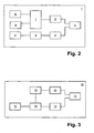
- Fig. 2 shows a schematic block diagram of a transmitting device 1 for transmitting signals in a wireless communication system according to the present invention.
- the transmitting device 1 of the present invention as shown in Fig. 2 is only displayed with elements which are necessary for the implementation and the understanding of the present invention. All other necessary elements enabling the transmitting device 1 to transmit signals in a wireless communication system are not shown for the sake of clarity. However, in a practical implementation, all such elements, for example a power supply and the like would be implemented.
- the transmitting device 1 comprises a first set 2 of narrow beam antennas which is adapted to allow a transmission of signals into different directions.
- a first antenna control means 4 is provided which controls the first set 2 of narrow beam antennas either by steering the narrow beam antennas to different positions or by switching between the different narrow beam antennas.
- the first antenna control means itself is controlled by a first control means 5.
- the first control means 5 can be a base-stand processing and/or controlling means of the transmitting device 1 or any other suitable control unit.
- the first control means 5 is connected to a first memory 6 for storing data, information, applications, software codes and so forth.
- the transmitting device 1 is adapted to transmit signals in consecutive time frames, whereby examples of such frames are shown in Figs. 7a and 7b and will be explained later.
- the term "consecutive" does not necessarily mean that the frames are transmitted immediately one after the other.
- there might be an interval between two consecutive frames which e. g. can be used to handle the clock difference between a transmitting device 1 and a receiving side, such as the receiving device 10 as shown and explained in Fig. 3 , in order to support long time and high rate wireless communications, such as wireless high definition television or the like.
- the frame comprises a beacon and data frames.
- a beacon generator 9 for generating the beacon and a data means 8 are provided in the transmitting device.
- the data means 8 generates, collects, or obtains the data in any kind of suitable way and forwards the data to the frame generator 7.
- the beacon generator 9 also forwards the generated beacon to the frame generator 7 where the frames are formed. After a frame has been generated by the frame generator 7, the generated frames are then further processed in the usual manner, e. g. by modulating the frame information or the like, which are then upconverted and transmitted via first high frequency means 3 through the first set 2 of narrow beam antennas.
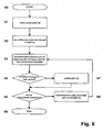
- FIG. 3 An example of a receiving device 10 for receiving signals in a wireless communication system according to the present invention is schematically shown in the block diagram of Fig. 3 .
- the receiving device 10 comprises a second set 11 of narrow beam antennas which is adapted to receive signals via different transmission paths.
- a second antenna control means 13 is able to control the beaming direction of the second set 11 of narrow beam antennas either by steering the narrow beam antennas to different positions or by switching between the different narrow beam antennas.
- the second antenna control means itself is under the control of a second control means 14.
- the second control 14 can be any kind of suitable control means, such as a base band processing means of the receiving device 10, or any other suitable control and/or processing device.
- the second control means 14 is connected to second memory 15 adapted to store data, information, applications, software programs and so forth necessary for the operation of the receiving device 10.
- the receiving device 10 further comprises a second high frequency section 12 which is used to down convert the received signals via the second set 11 of narrow beam antennas, which signals are then further processed in the usual manner in the receiving device 10.
- a path estimator 16 is adapted to perform an estimation of the quality of the used path on the basis of the received beacon.
- the path estimation information derived by the path estimator 16 can e. g. be used in the second control means 14 for changing the beaming direction to a suitable position.
- Fig. 3 only shows the necessary elements for understanding the present invention. In a practical implementation the receiving device 10 would comprise all other necessary elements for the operation of the receiving device 10 enabling the reception of signals in a wireless communication system.
- the receiving device 10 also comprises all necessary elements and functionalities to transmit signals in the wireless communication system either via the second set 11 of antennas or a separate transmission antenna.
- the transmitting device 1 comprises all necessary elements and functionalities enabling the reception of the signals in the wireless communication system either via the first set 2 of antennas or a separate reception antenna.
- the elements and functionalities of the transmitting device 1 shown and explained in relation to Fig. 2 and of the receiving device 10 shown and explained in relation to Fig. 3 could be combined in a communication device enabling the transmission and reception of signals in the wireless communication system.
- Figs. 4a and 4b show a communication system comprising a transmitting device 1 and a receiving device 10 according to the present invention.
- the transmitting device 1 hereby comprises three narrow beam antennas 2a, 2b and 2c each having a different beaming direction.
- the receiving device 10 as well comprises three narrow beam antennas 11a, 11b and 11c also each having a different beaming direction.
- the transmitting device 1 and the receiving device 10 negotiate a transmission scheme comprising a list of transmission paths that can be used for transmission. As shown in the example of Fig.
- the transmitting device When transmitting now the different data frames, the transmitting device does not only use one single path but transmits each frame via a different transmission path according to a round robin scheduling. For example, the transmitting device 1 transmits the first frame 23a via the antenna 2b and the transmission path P 0 to the receiving device 10. The second frame 23b is then transmitted over the antenna 2a and the transmission path P 1 to the antenna 11a of the receiving device 10. The third frame 23c is then transmitted over the third antenna 2c and the path P 2 to the receiving device 10.
- Fig. 4a The advantage of the communication system is shown in Fig. 4a where, as according to the state of art, after the transmission of the first frame 23a an obstacle 24 gets in the way of the line of sight transmission path P 0 . Due to the round robin scheduling and the transmission of subsequent frames via different transmission paths the second and the third frame 23b and 23c are not transmitted over the blocked path P 0 and therefore the possibility that a frame gets lost is decreased.
- the present invention is not limited to a round robin scheduling algorithm but may implement any other path hopping scheme or algorithm that provides the possibility to use different paths for subsequent frames.
- the present invention proposes to constantly monitor the paths that may be used for a transmission of a data frame. So the transmitting device 1 and the receiving device 10 both hold a list of paths having a good path quality that can be used for transmission. Due to the monitoring of the path of the actual path list it can be detected if either a path out of the actual path list has a decreased quality and should therefore be removed from the path list or if a path that is actually not in the path list has an increased quality and therefore can be also used as a possible transmission path.
- the present invention is carried out by using the MAC protocol.
- the MAC protocol takes into account the very specific application scenarios of the communication system.
- the main application scenario is a peer-to-peer connection between a sending and a receiving note.
- the MAC protocol distinguished two node classes, master and slave devices. In most cases, masters are stationary devices, whereas slaves may be portable devices but in the present invention, masters and slaves in both cases may be portable devices.
- Base of the MAC protocol is a super frame as shown in Fig. 7a with a definition of 10 msec.
- the master indicates the start of a super frame by sending a beacon BSF periodically every 10 msec.
- the beacon is followed by a contention access period CAP during which nodes which are not known to the master yet can send a registration request.
- the beacon is sent alternatively via the master's antennas. If a slave nodes response to a beacon, the master knows via which antenna the slave node can be reached initially.
- the contention access period CAP follow the downlink and uplink communication slots, where downlink denotes the direction from master to slave, and uplink from slave to master, respectively.
- the up- and downlink slots can have different lengths, i.e., they do not have to be symmetric.
- Either the master or the slave can initiate a connection. If a slave is the originator, it uses the contention access period to send a connection request to the master, which in turn assigns a number of up- and downstream slots to this slave. The upstream slots will be used for communication to the master by the slave from that point onward.
- a beacon super frame is sent periodically in which only beacons are sent, but via all different antennas of the master. Thus the slave can determine whether it receives beacons from the master via other paths than the currently active path.
- the present invention with a transmitting device 1 and a receiving device 10 depending on the number of narrow beam antennas, there are several possible communication paths between the transmitting device 1 and the receiving device 10.
- the present invention is not restricted to a number of two or three narrow beam antennas but may implement also more beam antennas for the transmitting device 1 and the receiving device 10.
- the present invention is not limited to a communication system comprising a transmitting device 1 and a receiving device 10, each having several narrow beam antennas, but is also related to a communication system having either a transmitting device 1 with narrow beam antennas or a receiving device 10 with narrow beam antennas, whereby the respectively other device only has a single wide beam antenna.
- the master For network formation, the master periodically sends beacons in a 10 msec super frame via all antennas. If a slave comes in range, it waits for a sufficient amount of time, i.e., at least 10msec per antenna before switching to the next antenna. When receiving a signal from the master via the currently selected antenna, it notifies the master through an immediate MAC control message.
- Fig. 7b show a simplified block diagram of a frame as transmitted and received in the present invention.
- the frame hereby comprises a beacon BSF and several data frames.
- the data frames hereby may be transmitted either from the transmitting device to the receiving device or vice versa.
- the super frame may also comprise other sequences, such as a contention access period, training sequences, or other preamble sections. For the sake of clarity, in the following description it is only referred to the beacon and the several data frames.
- Fig. 5 shows an example of the establishing of transmission paths.
- the first transmission path P 0 is the line of sight transmission path between the antenna 2c of the transmitting device 1 and the antenna 11c of the receiving device 10.
- the transmitting device 1 will then continue to send out beacons via the other antennas in order to find additional transmission paths.
- an additional transmission path P 1 where the electromagnetic wave is reflected by an object 22, is found between the antenna 2a of the transmitting device 1 and the antenna 11a of the receiving device 10.
- the transmitting device 1 and the receiving device 10 thereby both have a list of possible communication paths, in this case the paths P 0 and P 1 .
- This list comprises the communication path whose channel quality is high enough for data communication as well as the corresponding antenna beam IDs which has to be utilized to establish the communication link.
- the possible transmission paths change both lists, i.e., the path list of the transmitting device 1 as well as the path list of the receiving device 10 have to be changed accordingly.
- step S1 the actual path list is checked.
- step S2 the transmitting device transmits the data frames via the first path out of the path list and/or the receiving device receives data frames via a first path out of the actual path list.
- step S3 which can also be before the step S2 or at the same time as step S2, a beacon is transmitted and/or received via at least one path that has not been used for the transmission and/or reception of the data in step S2.
- step S4 it is checked if according to the transmitted and/or received beacon, a change in path quality has been detected.
- a change in path quality may be either that a path which is comprised in the actual path list is not good enough anymore to be used as a possible communication channel or a change in path quality may also be the case that a path which previously has no good transmission properties and therefore was not used for a possible transmission channel now has an increased channel quality and can be used for a possible transmission path. If a change in path quality in step S4 is detected then in step S7 the path list is updated, i.e., paths of the path list having a decreased quality are removed from the path list and paths not being on the list having an increased channel quality are added to the path list.
- step S5 it is checked if the end of the transmission and/or reception is reached. In case that there are no more data frames that shall be transmitted, the communication ends in step S6. Otherwise, if there is a need of a further transmission of data frames, then the next data frame in step S8 is transmitted and/or received via a further path out of the path list, whereby the path list is either the original path list or the updated path list, and whereby the further path is not the same path as the first one used in step S2.
- step S3 may also be concurrently to step S8, where again beacons are sent over the other paths in order to check the channel quality.
- the list of useable paths is constantly updated.
- the MAC protocol uses beacons in its super frames.
- a super frame starts with a beacon BSF, followed by one or several data frames DF or control frames, all transmitted from the master to the slave. Thereafter the slave transmits its data or control frames to the master.
- the master and the slaves are using the previously negotiated active beam path and the respective antennas allowing a transmission over the selected beam path.
- the master and the slave utilize in every super frame a different antenna beam in order to test the channel quality of this test beam channel.
- the master and slave negotiate a path hopping scheme, e.g. a round robin scheduling of the data transmission. Assuming the availability of three paths, only every third frame is transmitted over the same path. If one of those paths is blocked by an obstacle, the probability is 33% that a frame gets lost before the blocked path is removed from the list of active paths. This is only the case if the path gets blocked while transmitting a frame. In general terms, if the master and slave can communicate via n possible paths, the probability that a path gets blocked while or just before transmitting a frame is 1 n .
- a path hopping scheme e.g. a round robin scheduling of the data transmission. Assuming the availability of three paths, only every third frame is transmitted over the same path. If one of those paths is blocked by an obstacle, the probability is 33% that a frame gets lost before the blocked path is removed from the list of active paths. This is only the case if the path gets blocked while transmitting a frame. In general terms, if the master and slave can communicate via
- the distribution of the super frame transmission can be adapted accordingly. If, e.g. the line of sight paths becomes more often blocked than the other non line of sight paths, the path hopping scheme may utilize the line of sight less than the other paths, thus decreasing the probability of frame loss even more should the path be blocked.
- the present invention provides a data transmission via different paths.
- the present invention proposes a path monitoring of the quality of the other paths which are not actually used for data transmission.
- the transmitting device 1 can while sending a data frame via one path monitor the other known paths to determine the path quality. If the transmitting device 1 based on the feedback of the receiving device determines during these checks that a path got blocked, this path is removed from the path candidate list. Ideally, in this case no data losses occur, since the blocked path will not be used for transmission on the next round.
- the path monitoring that is performed during the transmission will have determined that this path is blocked and the removed the path from the list of paths to be used for transmission.
- the present invention proposes two embodiments, but is not limited to the presented embodiments.
- FIG. 8a A first embodiment of a path monitoring scheme is shown in Fig. 8a .
- the time axis is hereby provided from the left to the right.
- Each line denotes a different path, in the present example four paths are provided.
- the transmission starts with super frame no. 1.
- a beacon is sent over path 2 and the transmission of the data frames happens via path 1. That means that path 1 has been negotiated previously as the path having the best channel qualities and therefore the data frame transmission starts with path 1.
- the beacon is sent over path 2, so the path quality of path 2 can be monitored.
- the data frames are sent over path 2.
- the beacon is sent over the next path of the path list which in the present example is path 3. Thereby, again it can be checked if path 3 provides good channel qualities or if it is blocked. Again, in case that path 3 provides good channel qualities then the next data frame transmission is accomplished via path 3 and so on.
- the beacon may not only be sent over a single path but over more paths in order to concurrently monitor several paths.
- the advantage of this first embodiment is that no additional time is needed to scan the available paths which increases the maximum data rate.
- FIG. 8b A second embodiment is shown in Fig. 8b .
- the monitoring process can be performed between the transmission of subsequent super frames.
- the super frame 1 is entirely sent via path no. 1.
- an inter super frame is used where beacons are sent over all other paths in order to monitor the path quality of the other paths.
- the next path on the path list in the present example path 2
- the next super frame 2 will be sent over path 2.
- This scan of all known paths in the inter super frame period in order to determine the path status requires that the receiving device answers immediately via the same path. If the path is blocked, the transmitting device will not receive the reply and drops the path from the next scheduled data transmission.
- the distribution of the different frames over the different paths is determined by a round robin scheduling algorithm but also other algorithms may be used.
- the round robin scheduling reduces the probability of lost frames due to an obstacle in the path to 1 n , if path monitoring is employed simultaneously to the frame transmission.
Landscapes
- Engineering & Computer Science (AREA)
- Computer Networks & Wireless Communication (AREA)
- Signal Processing (AREA)
- Quality & Reliability (AREA)
- Mobile Radio Communication Systems (AREA)
- Radio Transmission System (AREA)
Claims (33)
- Dispositif de transmission (1) destiné à transmettre des signaux dans un système de communication sans fil, dans lequel lesdits signaux sont transmis dans des trames consécutives (23a, 23b, 23c), chaque trame comportant une balise (BSF) et des trames de données (DF), ledit dispositif de transmission (1) comportant un premier ensemble d'antennes à faisceau étroit (2a, 2b, 2c), chaque antenne à faisceau étroit (2a, 2b, 2c) présentant une direction de faisceau distincte correspondant à l'un d'un nombre de chemins de transmission distincts (P0, P1, P2) allant dudit dispositif de transmission (1) à un dispositif de réception, et un premier moyen de commande (5) apte à commander la transmission desdites trames (23a, 23b, 23c), les trames de données (DF) d'une première trame de deux trames consécutives respectivement (23a, 23b, 23c) étant transmises via une antenne à faisceau étroit distincte (2a, 2b, 2c) de celle des trames de données (DF) de la seconde trame desdites deux trames consécutives respectivement (23a, 23b, 23c) selon un schéma de saut de chemin.
- Dispositif de transmission (1) selon la revendication 1,
dans lequel un générateur de balise (9) génère la balise (BSF) en vue d'estimer la qualité de chemin. - Dispositif de transmission (1) selon la revendication 1 ou 2,
dans lequel une première mémoire (6) est apte à stocker une liste de chemins qui peuvent être utilisés en qualité de chemins de transmission (P0, P1, P2) - Dispositif de transmission (1) selon l'une quelconque des revendications 1 à 3,
dans lequel le premier moyen de commande (5) met à jour la liste de chemins stockée dans la première mémoire (6) en fonction d'une modification de la qualité de chemin. - Dispositif de transmission (1) selon la revendication 4,
dans lequel le premier moyen de commande (5) supprime un chemin présentant une qualité de chemin diminuée de la liste de chemins stockée dans la première mémoire (6). - Dispositif de transmission (1) selon la revendication 5 ou 4,
dans lequel le premier moyen de commande (5) ajoute un chemin présentant une qualité de chemin améliorée à la liste de chemins stockée dans la première mémoire (6). - Dispositif de transmission (1) selon l'une quelconque des revendications 1 à 6,
dans lequel la balise (BSF) et les trames de données (DF) d'une trame sont envoyées via des antennes à faisceau étroit distinctes (2a, 2b, 2c). - Dispositif de transmission (1) selon l'une quelconque des revendications 1 à 7,
dans lequel au moins une balise supplémentaire (BSF) est envoyée entre deux trames (23a, 23b, 23c). - Dispositif de réception (10) destiné à recevoir des signaux dans un système de communication sans fil, dans lequel lesdits signaux sont reçus dans des trames consécutives (23a, 23b, 23c), chaque trame comportant une balise (BSF) et des trames de données (DF), ledit dispositif de réception (10) comportant
un second ensemble (11) d'antennes à faisceau étroit (11a, 11b, 11c), chaque antenne à faisceau étroit (11a, 11b, 11c) présentant une direction de faisceau distincte correspondant à l'un d'un nombre de chemins de transmission distincts (P0, P1, P2) allant d'un dispositif de transmission audit dispositif de réception (10) ; et
un second moyen de commande (14) apte à commander la réception desdites trames (23a, 23b, 23c), les trames de données (DF) d'une première trame de deux trames consécutives respectivement (23a, 23b, 23c) étant reçues via une antenne à faisceau étroit distincte (11a, 11b, 11c) de celle des trames de données (DF) de la seconde trame desdites deux trames consécutives respectivement (23a, 23b, 23c) selon un schéma de saut de chemin. - Dispositif de réception (10) selon la revendication 9,
dans lequel un estimateur de chemin (16) estime la qualité de chemin sur la base de la balise reçue (BSF). - Dispositif de réception (10) selon la revendication 9 ou 10,
dans lequel une seconde mémoire (15) est apte à stocker une liste de chemins qui peuvent être utilisés en qualité de chemins de transmission (P0, P1, P2). - Dispositif de réception (10) selon l'une quelconque des revendications 9 à 11,
dans lequel le second moyen de commande (14) met à jour la liste de chemins stockés dans la seconde mémoire (15) en fonction d'une modification de la qualité de chemin. - Dispositif de réception (10) selon la revendication 12,
dans lequel le second moyen de commande (14) supprime un chemin présentant une qualité de chemin diminuée de la liste de chemins stockés dans la seconde mémoire (15). - Dispositif de réception (10) selon la revendication 12 ou 13,
dans lequel le second moyen de commande (14) ajoute un chemin présentant une qualité de chemin améliorée à la liste de chemins stockés dans la seconde mémoire (15). - Dispositif de réception (10) selon l'une quelconque des revendications 9 à 14,
dans lequel la balise (BSF) et les trames de données (DF) d'une trame sont reçues via des antennes à faisceau étroit distinctes (11a, 11b, 11c). - Dispositif de réception (10) selon l'une quelconque des revendications 9 à 15,
dans lequel au moins une balise supplémentaire (BSF) est reçue entre deux trames (23a, 23b, 23c). - Système de communication comportant un dispositif de transmission (1) selon l'une quelconque des revendications 1 à 8 et un dispositif de réception (10) selon l'une quelconque des revendications 9 à 16.
- Procédé destiné à transmettre des signaux dans un système de communication sans fil, dans lequel lesdits signaux sont transmis dans des trames consécutives (23a, 23b, 23c), chaque trame comportant une balise (BSF) et des trames de données (DF), ledit procédé de transmission comportant les étapes ci-dessous consistant à fournir un premier ensemble (2) d'antennes à faisceau étroit (2a, 2b, 2c), chaque antenne à faisceau étroit (2a, 2b, 2c) présentant une direction de faisceau distincte correspondant à l'un d'un nombre de chemins de transmission distincts (P0, P1, P2) allant d'un dispositif de transmission à un dispositif de réception, et
transmettre les trames de données (DF) d'une première trame de deux trames consécutives respectivement (23a, 23b, 23c) via une antenne à faisceau étroit distincte (2a, 2b, 2c) de celle des trames de données (DF) de la seconde trame desdites deux trames consécutives respectivement (23a, 23b, 23c) selon un schéma de saut de chemin. - Procédé selon la revendication 18,
ledit procédé comportant les étapes ci-dessous consistant à générer la balise (BSF) en vue d'estimer la qualité de chemin. - Procédé selon la revendication 18 ou 19,
ledit procédé comportant les étapes ci-dessous consistant à stocker une liste de chemins qui peuvent être utilisés en qualité de chemins de transmission (P0, P1, P2) dans une première mémoire (6). - Procédé selon l'une quelconque des revendications 18 à 20,
ledit procédé comportant les étapes ci-dessous consistant à mettre à jour la liste de chemins stockée dans la première mémoire (6) en fonction d'une modification de la qualité de chemin. - Procédé selon la revendication 21,
ledit procédé comportant les étapes ci-dessous consistant à supprimer un chemin présentant une qualité de chemin diminuée de la liste de chemins stockée dans la première mémoire (6). - Procédé selon la revendication 21 ou 22,
ledit procédé comportant les étapes ci-dessous consistant à ajouter un chemin présentant une qualité de chemin améliorée à la liste de chemins stockée dans la première mémoire (6). - Procédé selon l'une quelconque des revendications 18 à 23,
ledit procédé comportant les étapes ci-dessous consistant à envoyer la balise (BSF) et les trames de données (DF) d'une trame via des antennes à faisceau étroit distinctes (2a, 2b, 2c). - Procédé selon l'une quelconque des revendications 18 à 24,
ledit procédé comportant les étapes ci-dessous consistant à envoyer au moins une balise supplémentaire (BSF) entre deux trames (23a, 23b, 23c). - Procédé destiné à recevoir des signaux dans un système de communication sans fil, dans lequel lesdits signaux sont reçus dans des trames consécutives (23a, 23b, 23c), chaque trame comportant une balise (BSF) et des trames de données (DF), ledit procédé de réception comportant les étapes ci-dessous consistant à
fournir un second ensemble (11) d'antennes à faisceau étroit (11a, 11b 11c), chaque antenne à faisceau étroit (11a, 11b, 11c) présentant une direction de faisceau distincte correspondant à l'un d'un nombre de chemins de transmission distincts (P0, P1, P2) allant d'un dispositif de transmission à un dispositif de réception, et
recevoir les trames de données (DF) d'une première trame de deux trames consécutives respectivement (23a, 23b, 23c) via une antenne à faisceau étroit distincte (11a, 11b, 11c) de celle des trames de données (DF) de la seconde trame desdites deux trames consécutives respectivement (23a, 23b, 23c) selon un schéma de saut de chemin. - Procédé selon la revendication 26,
ledit procédé comportant les étapes ci-dessous consistant à estimer la qualité de chemin sur la base de la balise reçue (BSF). - Procédé selon la revendication 26 ou 27,
ledit procédé comportant les étapes ci-dessous consistant à stocker une liste de chemins qui peuvent être utilisés en qualité de chemins de
transmission (P0, P1, P2) dans une seconde mémoire (15). - Procédé selon l'une quelconque des revendications 26 à 28,
ledit procédé comportant les étapes ci-dessous consistant à mettre à jour la liste de chemins stockés dans la seconde mémoire (15) en fonction d'une modification de la qualité de chemin. - Procédé selon la revendication 29,
ledit procédé comportant les étapes ci-dessous consistant à supprimer un chemin présentant une qualité de chemin diminuée de la liste de chemins stockés dans la seconde mémoire (15). - Procédé selon la revendication 29 ou 30,
ledit procédé comportant les étapes ci-dessous consistant à ajouter un chemin présentant une qualité de chemin améliorée à la liste de chemins stockés dans la seconde mémoire (15). - Procédé selon l'une quelconque des revendications 26 à 31,
ledit procédé comportant les étapes ci-dessous consistant à recevoir la balise (BSF) et les trames de données (DF) d'une trame via des antennes à faisceau étroit distinctes (11a, 11b, 11c). - Procédé selon l'une quelconque des revendications 26 à 32,
ledit procédé comportant les étapes ci-dessous consistant à recevoir au moins une balise supplémentaire (BSF) entre deux trames (23a, 23b, 23c).
Priority Applications (4)
| Application Number | Priority Date | Filing Date | Title |
|---|---|---|---|
| EP07105275A EP1976149B1 (fr) | 2007-03-29 | 2007-03-29 | Procédé et dispositif pour transmettre des signaux dans un système de communication sans fil, dispositif de réception et procédé pour la réception de signaux dans un système de communication sans fil |
| US12/026,818 US8014828B2 (en) | 2007-03-29 | 2008-02-06 | Method and device for transmitting signals in a wireless communication system and method and device for receiving signals in a wireless communication system |
| JP2008091811A JP5284667B2 (ja) | 2007-03-29 | 2008-03-31 | 無線通信システムにおいて信号を送信するための方法及び装置、並びに無線通信システムにおいて信号を受信するための方法及び装置 |
| CN200810090710.2A CN101277537B (zh) | 2007-03-29 | 2008-03-31 | 发射设备、接收设备、发射方法和接收方法 |
Applications Claiming Priority (1)
| Application Number | Priority Date | Filing Date | Title |
|---|---|---|---|
| EP07105275A EP1976149B1 (fr) | 2007-03-29 | 2007-03-29 | Procédé et dispositif pour transmettre des signaux dans un système de communication sans fil, dispositif de réception et procédé pour la réception de signaux dans un système de communication sans fil |
Publications (2)
| Publication Number | Publication Date |
|---|---|
| EP1976149A1 EP1976149A1 (fr) | 2008-10-01 |
| EP1976149B1 true EP1976149B1 (fr) | 2011-10-19 |
Family
ID=38200391
Family Applications (1)
| Application Number | Title | Priority Date | Filing Date |
|---|---|---|---|
| EP07105275A Not-in-force EP1976149B1 (fr) | 2007-03-29 | 2007-03-29 | Procédé et dispositif pour transmettre des signaux dans un système de communication sans fil, dispositif de réception et procédé pour la réception de signaux dans un système de communication sans fil |
Country Status (4)
| Country | Link |
|---|---|
| US (1) | US8014828B2 (fr) |
| EP (1) | EP1976149B1 (fr) |
| JP (1) | JP5284667B2 (fr) |
| CN (1) | CN101277537B (fr) |
Families Citing this family (37)
| Publication number | Priority date | Publication date | Assignee | Title |
|---|---|---|---|---|
| EP2211483B1 (fr) * | 2009-01-23 | 2016-05-25 | Sony Corporation | Dispositif à suspension de rouleau guide réglable |
| US8908616B2 (en) * | 2010-07-15 | 2014-12-09 | Canon Kabushiki Kaisha | Methods and devices for transmitting and receiving data signals in a wireless network over a plurality of transmission paths |
| CN103733527B (zh) | 2011-04-07 | 2015-10-07 | 蓝色多瑙河系统公司 | 在无线系统中实现高平均频谱效率的技术 |
| JP5440579B2 (ja) * | 2011-09-27 | 2014-03-12 | 株式会社デンソー | 隊列走行装置 |
| US9144082B2 (en) | 2012-06-13 | 2015-09-22 | All Purpose Networks LLC | Locating and tracking user equipment in the RF beam areas of an LTE wireless system employing agile beam forming techniques |
| US9882950B2 (en) | 2012-06-13 | 2018-01-30 | All Purpose Networks LLC | Methods and systems of an all purpose broadband network |
| US9094803B2 (en) | 2012-06-13 | 2015-07-28 | All Purpose Networks LLC | Wireless network based sensor data collection, processing, storage, and distribution |
| US9125064B2 (en) | 2012-06-13 | 2015-09-01 | All Purpose Networks LLC | Efficient reduction of inter-cell interference using RF agile beam forming techniques |
| US9084155B2 (en) | 2012-06-13 | 2015-07-14 | All Purpose Networks LLC | Optimized broadband wireless network performance through base station application server |
| US9031511B2 (en) | 2012-06-13 | 2015-05-12 | All Purpose Networks LLC | Operational constraints in LTE FDD systems using RF agile beam forming techniques |
| US9503927B2 (en) | 2012-06-13 | 2016-11-22 | All Purpose Networks LLC | Multiple-use wireless network |
| US9107094B2 (en) | 2012-06-13 | 2015-08-11 | All Purpose Networks LLC | Methods and systems of an all purpose broadband network |
| US9084143B2 (en) | 2012-06-13 | 2015-07-14 | All Purpose Networks LLC | Network migration queuing service in a wireless network |
| US9125123B2 (en) | 2012-06-13 | 2015-09-01 | All Purpose Networks LLC | Efficient delivery of real-time asynchronous services over a wireless network |
| US9179352B2 (en) | 2012-06-13 | 2015-11-03 | All Purpose Networks LLC | Efficient delivery of real-time synchronous services over a wireless network |
| US9219541B2 (en) | 2012-06-13 | 2015-12-22 | All Purpose Networks LLC | Baseband data transmission and reception in an LTE wireless base station employing periodically scanning RF beam forming techniques |
| US8565689B1 (en) | 2012-06-13 | 2013-10-22 | All Purpose Networks LLC | Optimized broadband wireless network performance through base station application server |
| US9144075B2 (en) * | 2012-06-13 | 2015-09-22 | All Purpose Networks LLC | Baseband data transmission and reception in an LTE wireless base station employing periodically scanning RF beam forming techniques |
| US9179392B2 (en) | 2012-06-13 | 2015-11-03 | All Purpose Networks LLC | Efficient delivery of real-time asynchronous services over a wireless network |
| US9179354B2 (en) | 2012-06-13 | 2015-11-03 | All Purpose Networks LLC | Efficient delivery of real-time synchronous services over a wireless network |
| US9137675B2 (en) | 2012-06-13 | 2015-09-15 | All Purpose Networks LLC | Operational constraints in LTE TDD systems using RF agile beam forming techniques |
| US9131385B2 (en) | 2012-06-13 | 2015-09-08 | All Purpose Networks LLC | Wireless network based sensor data collection, processing, storage, and distribution |
| WO2014067044A1 (fr) * | 2012-10-29 | 2014-05-08 | Qualcomm Incorporated | Enregistrement et sondage de dispositif dans un réseau d'accès multiple par répartition dans le temps |
| DE102013215729B4 (de) * | 2013-03-26 | 2025-12-31 | Bayerische Motoren Werke Aktiengesellschaft | Verfahren und Vorrichtung zur Auswahl eines Funkübertragungskanals in einem Funksystem |
| US9763166B2 (en) * | 2013-05-10 | 2017-09-12 | Elwha Llc | Dynamic point to point mobile network including communication path monitoring and analysis aspects system and method |
| US9832728B2 (en) | 2013-05-10 | 2017-11-28 | Elwha Llc | Dynamic point to point mobile network including origination user interface aspects system and method |
| US9591692B2 (en) | 2013-05-10 | 2017-03-07 | Elwha Llc | Dynamic point to point mobile network including destination device aspects system and method |
| US9559766B2 (en) | 2013-05-10 | 2017-01-31 | Elwha Llc | Dynamic point to point mobile network including intermediate device aspects system and method |
| WO2015106813A1 (fr) * | 2014-01-16 | 2015-07-23 | Telefonaktiebolaget L M Ericsson (Publ) | Commande améliorée d'antennes directrices pour des liaisons sans fil |
| EP3073795B1 (fr) * | 2015-03-25 | 2018-05-02 | Televic Conference NV | Système de téléconférence sans fil et son procédé de configuration |
| JP6472704B2 (ja) * | 2015-04-24 | 2019-02-20 | 国立研究開発法人情報通信研究機構 | 無線通信システム |
| EP3171453B1 (fr) * | 2015-11-17 | 2019-02-13 | VEGA Grieshaber KG | Dispositif d'antenne et procédé de fonctionnement d'un dispositif d'antenne |
| CN112887000B (zh) * | 2016-05-31 | 2022-07-15 | 中兴通讯股份有限公司 | 信息反馈方法、装置及系统 |
| EP3662370B1 (fr) | 2018-01-08 | 2023-12-27 | All Purpose Networks, Inc. | Système internet des objets avec réseau de communication efficace et sécurisé |
| US10827019B2 (en) | 2018-01-08 | 2020-11-03 | All Purpose Networks, Inc. | Publish-subscribe broker network overlay system |
| US12041396B2 (en) * | 2020-07-16 | 2024-07-16 | R9 Labs, Llc | Systems and methods for processing data proximate to the point of collection |
| WO2023007473A1 (fr) * | 2021-07-30 | 2023-02-02 | Lenovo (Singapore) Pte. Ltd. | Association de faisceaux pour une période de trame mixte |
Family Cites Families (14)
| Publication number | Priority date | Publication date | Assignee | Title |
|---|---|---|---|---|
| US3928804A (en) * | 1973-03-30 | 1975-12-23 | Communications Satellite Corp | Zone sharing transponder concept |
| JPH09181663A (ja) * | 1995-12-26 | 1997-07-11 | Kokusai Electric Co Ltd | ダイバーシチ通信方法とその装置 |
| JP3271233B2 (ja) * | 1996-02-07 | 2002-04-02 | 日本電信電話株式会社 | ダイバーシチ方法 |
| JPH10163937A (ja) * | 1996-12-04 | 1998-06-19 | Y R P Ido Tsushin Kiban Gijutsu Kenkyusho:Kk | アンテナ切り替え制御方式 |
| SE517197C2 (sv) * | 1999-04-15 | 2002-05-07 | Ericsson Telefon Ab L M | Adaptiv sektorindelning |
| JP2001127680A (ja) * | 1999-10-28 | 2001-05-11 | Matsushita Electric Ind Co Ltd | アンテナ制御装置及びアンテナ制御方法 |
| JP2001285156A (ja) * | 2000-03-29 | 2001-10-12 | Clarion Co Ltd | ダイバーシティ受信機 |
| US20040185782A1 (en) | 2003-03-17 | 2004-09-23 | Halford Steven Dennis | Technique for selecting a signal path in an antenna system |
| FI20031053A0 (fi) * | 2003-07-10 | 2003-07-10 | Nokia Corp | Lähetysmenetelmä ja tukiasema |
| JP2005110228A (ja) * | 2003-09-10 | 2005-04-21 | Matsushita Electric Ind Co Ltd | セキュア通信方法および送信装置、受信装置 |
| US7558554B2 (en) * | 2004-02-24 | 2009-07-07 | Broadcom Corporation | Method and system for antenna selection diversity with prediction |
| EP3576310B1 (fr) | 2004-09-10 | 2023-03-22 | InterDigital Technology Corporation | Mise en uvre d'une antenne intelligente dans un réseau local sans fil |
| EP2259617B1 (fr) | 2004-11-19 | 2013-01-23 | Sony Deutschland Gmbh | Dispositif de transmission et procédé pour établir une communication sans fil |
| EP2296294B1 (fr) * | 2006-10-09 | 2013-01-09 | Sony Deutschland Gmbh | Procédé et dispositifs de transmission et réception de signaux dans un système de communication sans fil avec une structure de trame spéciale |
-
2007
- 2007-03-29 EP EP07105275A patent/EP1976149B1/fr not_active Not-in-force
-
2008
- 2008-02-06 US US12/026,818 patent/US8014828B2/en not_active Expired - Fee Related
- 2008-03-31 JP JP2008091811A patent/JP5284667B2/ja not_active Expired - Fee Related
- 2008-03-31 CN CN200810090710.2A patent/CN101277537B/zh not_active Expired - Fee Related
Also Published As
| Publication number | Publication date |
|---|---|
| JP2008263603A (ja) | 2008-10-30 |
| US8014828B2 (en) | 2011-09-06 |
| JP5284667B2 (ja) | 2013-09-11 |
| CN101277537B (zh) | 2013-01-02 |
| EP1976149A1 (fr) | 2008-10-01 |
| US20080242251A1 (en) | 2008-10-02 |
| CN101277537A (zh) | 2008-10-01 |
Similar Documents
| Publication | Publication Date | Title |
|---|---|---|
| EP1976149B1 (fr) | Procédé et dispositif pour transmettre des signaux dans un système de communication sans fil, dispositif de réception et procédé pour la réception de signaux dans un système de communication sans fil | |
| US11297481B2 (en) | Multi-band millimeter wave discovery in WLAN distribution networks | |
| US10499320B2 (en) | Mesh assisted node discovery | |
| Nitsche et al. | IEEE 802.11 ad: directional 60 GHz communication for multi-Gigabit-per-second Wi-Fi | |
| KR102360477B1 (ko) | 무선 네트워크들에서의 온디맨드 경로 동기화 및 빔포밍 | |
| US8755302B2 (en) | Method and system for ad-hoc communications over millimeter wave wireless channels in wireless systems | |
| US8135400B2 (en) | Method and system for device discovery in wireless communication | |
| JP5073066B2 (ja) | 無線ネットワークにおいてアソシエーションおよび再アソシエーションを実行するための構成 | |
| KR102280981B1 (ko) | 다중 대역 밀리미터 파 네트워크 발견 | |
| KR20090116609A (ko) | 채널 선택 및 대역폭 예약을 이용하는 무선 통신 방법 및시스템 | |
| JP7345735B2 (ja) | Wlanネットワークにおけるバックアップルートを伴うマルチホップルーティングプロトコル | |
| WO2019002991A1 (fr) | Découverte de nœuds voisins dans des réseaux maillés sans fil avec transmissions directionnelles | |
| KR101952308B1 (ko) | 통신시스템에서 일 대 다 통신을 수행하는 장치 및 방법 | |
| KR102454139B1 (ko) | 지향성 비컨 전송 및 수신 활동 표시 | |
| Ajorloo et al. | Modeling beacon period length of the UWB and 60-GHz mmWave WPANs based on ECMA-368 and ECMA-387 standards | |
| KR20190057041A (ko) | 무선 메쉬 네트워크에서의 메쉬 피어 링크 설정 방법 및 장치, 그리고 채널 스위치 방법 및 장치 | |
| JP2002158616A (ja) | 偏波が変化する送信信号を生成するための無線システム、アンテナ構成、および偏波変調器 | |
| Song et al. | A survey of single and multi-hop link schedulers for mmWave wireless systems | |
| KR101683932B1 (ko) | 멀티-섹터 안테나를 갖는 단말을 캘리브레이션하기 위한 방법 및 메시 네트워크 단말 | |
| KR101733174B1 (ko) | 무선 네트워크의 빔 호핑 방법 | |
| JP2006174145A (ja) | 無線装置 | |
| JP2001189687A (ja) | 通信制御方法、移動通信システム、基地局及び移動局 | |
| Santosa et al. | An efficient scheme to discover neighbors beyond omnidirectional transmission range | |
| HK1120169A (en) | Method for improving wireless network performance in a multi-cell communication network |
Legal Events
| Date | Code | Title | Description |
|---|---|---|---|
| PUAI | Public reference made under article 153(3) epc to a published international application that has entered the european phase |
Free format text: ORIGINAL CODE: 0009012 |
|
| AK | Designated contracting states |
Kind code of ref document: A1 Designated state(s): AT BE BG CH CY CZ DE DK EE ES FI FR GB GR HU IE IS IT LI LT LU LV MC MT NL PL PT RO SE SI SK TR |
|
| AX | Request for extension of the european patent |
Extension state: AL BA HR MK RS |
|
| 17P | Request for examination filed |
Effective date: 20090302 |
|
| 17Q | First examination report despatched |
Effective date: 20090402 |
|
| AKX | Designation fees paid |
Designated state(s): DE FR GB |
|
| GRAP | Despatch of communication of intention to grant a patent |
Free format text: ORIGINAL CODE: EPIDOSNIGR1 |
|
| RIC1 | Information provided on ipc code assigned before grant |
Ipc: H04B 7/06 20060101ALI20110304BHEP Ipc: H04B 7/04 20060101AFI20110304BHEP Ipc: H04B 7/08 20060101ALI20110304BHEP |
|
| GRAS | Grant fee paid |
Free format text: ORIGINAL CODE: EPIDOSNIGR3 |
|
| GRAA | (expected) grant |
Free format text: ORIGINAL CODE: 0009210 |
|
| AK | Designated contracting states |
Kind code of ref document: B1 Designated state(s): DE FR GB |
|
| REG | Reference to a national code |
Ref country code: GB Ref legal event code: FG4D |
|
| REG | Reference to a national code |
Ref country code: DE Ref legal event code: R096 Ref document number: 602007017956 Country of ref document: DE Effective date: 20111215 |
|
| PLBE | No opposition filed within time limit |
Free format text: ORIGINAL CODE: 0009261 |
|
| STAA | Information on the status of an ep patent application or granted ep patent |
Free format text: STATUS: NO OPPOSITION FILED WITHIN TIME LIMIT |
|
| 26N | No opposition filed |
Effective date: 20120720 |
|
| REG | Reference to a national code |
Ref country code: DE Ref legal event code: R097 Ref document number: 602007017956 Country of ref document: DE Effective date: 20120720 |
|
| PGFP | Annual fee paid to national office [announced via postgrant information from national office to epo] |
Ref country code: GB Payment date: 20130321 Year of fee payment: 7 Ref country code: FR Payment date: 20130408 Year of fee payment: 7 |
|
| GBPC | Gb: european patent ceased through non-payment of renewal fee |
Effective date: 20140329 |
|
| REG | Reference to a national code |
Ref country code: FR Ref legal event code: ST Effective date: 20141128 |
|
| PG25 | Lapsed in a contracting state [announced via postgrant information from national office to epo] |
Ref country code: GB Free format text: LAPSE BECAUSE OF NON-PAYMENT OF DUE FEES Effective date: 20140329 Ref country code: FR Free format text: LAPSE BECAUSE OF NON-PAYMENT OF DUE FEES Effective date: 20140331 |
|
| REG | Reference to a national code |
Ref country code: DE Ref legal event code: R084 Ref document number: 602007017956 Country of ref document: DE |
|
| PGFP | Annual fee paid to national office [announced via postgrant information from national office to epo] |
Ref country code: DE Payment date: 20210217 Year of fee payment: 15 |
|
| REG | Reference to a national code |
Ref country code: DE Ref legal event code: R119 Ref document number: 602007017956 Country of ref document: DE |
|
| PG25 | Lapsed in a contracting state [announced via postgrant information from national office to epo] |
Ref country code: DE Free format text: LAPSE BECAUSE OF NON-PAYMENT OF DUE FEES Effective date: 20221001 |