EP1976208A1 - Drahtloses Einzelträger Kommunikationssystem - Google Patents
Drahtloses Einzelträger Kommunikationssystem Download PDFInfo
- Publication number
- EP1976208A1 EP1976208A1 EP07006738A EP07006738A EP1976208A1 EP 1976208 A1 EP1976208 A1 EP 1976208A1 EP 07006738 A EP07006738 A EP 07006738A EP 07006738 A EP07006738 A EP 07006738A EP 1976208 A1 EP1976208 A1 EP 1976208A1
- Authority
- EP
- European Patent Office
- Prior art keywords
- pseudorandom
- noise
- cyclic prefix
- noise sequence
- signal
- Prior art date
- Legal status (The legal status is an assumption and is not a legal conclusion. Google has not performed a legal analysis and makes no representation as to the accuracy of the status listed.)
- Granted
Links
- 238000004891 communication Methods 0.000 title claims abstract description 67
- 125000004122 cyclic group Chemical group 0.000 claims abstract description 167
- 238000005314 correlation function Methods 0.000 claims description 56
- 238000000034 method Methods 0.000 claims description 53
- 238000012546 transfer Methods 0.000 claims description 38
- 230000009466 transformation Effects 0.000 claims description 38
- 238000003780 insertion Methods 0.000 claims description 9
- 230000037431 insertion Effects 0.000 claims description 9
- 230000002123 temporal effect Effects 0.000 claims description 8
- 238000013523 data management Methods 0.000 claims description 6
- 238000012545 processing Methods 0.000 claims description 6
- 230000008569 process Effects 0.000 claims description 3
- 238000005311 autocorrelation function Methods 0.000 description 14
- 230000000737 periodic effect Effects 0.000 description 11
- 238000010586 diagram Methods 0.000 description 9
- 230000004044 response Effects 0.000 description 5
- 230000008901 benefit Effects 0.000 description 4
- 230000008859 change Effects 0.000 description 3
- 230000000694 effects Effects 0.000 description 3
- 238000005562 fading Methods 0.000 description 3
- 230000002349 favourable effect Effects 0.000 description 3
- 238000007726 management method Methods 0.000 description 3
- 238000007476 Maximum Likelihood Methods 0.000 description 2
- 230000005540 biological transmission Effects 0.000 description 2
- 238000004364 calculation method Methods 0.000 description 2
- 230000000875 corresponding effect Effects 0.000 description 2
- 238000011084 recovery Methods 0.000 description 2
- 230000003044 adaptive effect Effects 0.000 description 1
- 239000000969 carrier Substances 0.000 description 1
- 239000012141 concentrate Substances 0.000 description 1
- 230000002596 correlated effect Effects 0.000 description 1
- 230000001419 dependent effect Effects 0.000 description 1
- 238000005516 engineering process Methods 0.000 description 1
- 238000012986 modification Methods 0.000 description 1
- 230000004048 modification Effects 0.000 description 1
- 239000004065 semiconductor Substances 0.000 description 1
- 230000035945 sensitivity Effects 0.000 description 1
- 238000001228 spectrum Methods 0.000 description 1
- 238000012549 training Methods 0.000 description 1
Images


Classifications
-
- H—ELECTRICITY
- H04—ELECTRIC COMMUNICATION TECHNIQUE
- H04L—TRANSMISSION OF DIGITAL INFORMATION, e.g. TELEGRAPHIC COMMUNICATION
- H04L25/00—Baseband systems
- H04L25/02—Details ; arrangements for supplying electrical power along data transmission lines
- H04L25/03—Shaping networks in transmitter or receiver, e.g. adaptive shaping networks
- H04L25/03006—Arrangements for removing intersymbol interference
- H04L25/03159—Arrangements for removing intersymbol interference operating in the frequency domain
-
- H—ELECTRICITY
- H04—ELECTRIC COMMUNICATION TECHNIQUE
- H04L—TRANSMISSION OF DIGITAL INFORMATION, e.g. TELEGRAPHIC COMMUNICATION
- H04L25/00—Baseband systems
- H04L25/02—Details ; arrangements for supplying electrical power along data transmission lines
- H04L25/03—Shaping networks in transmitter or receiver, e.g. adaptive shaping networks
- H04L25/03006—Arrangements for removing intersymbol interference
- H04L2025/03433—Arrangements for removing intersymbol interference characterised by equaliser structure
- H04L2025/03439—Fixed structures
- H04L2025/03522—Frequency domain
-
- H—ELECTRICITY
- H04—ELECTRIC COMMUNICATION TECHNIQUE
- H04L—TRANSMISSION OF DIGITAL INFORMATION, e.g. TELEGRAPHIC COMMUNICATION
- H04L27/00—Modulated-carrier systems
- H04L27/26—Systems using multi-frequency codes
- H04L27/2601—Multicarrier modulation systems
- H04L27/2602—Signal structure
- H04L27/2605—Symbol extensions, e.g. Zero Tail, Unique Word [UW]
- H04L27/2607—Cyclic extensions
Definitions
- the present invention relates to the field of single carrier wireless communication, in particular to the management of the time frame structure for the single carrier wireless communication.
- the wireless channel delay spread might be over tens of symbols which makes conventional time-domain channel equalizers including linear, decision feedback or maximum likelihood sequence estimation (MLSE) equalizer unrealistic.
- MSE maximum likelihood sequence estimation
- the present invention concentrates on the areas of single carrier wireless systems with frequency domain equalizer and provides means to eliminate the inter-frame interference due to multi-path fading, and simultaneously provides coarse frame timing, carrier synchronization and channel estimation without additional overhead.
- OFDM orthogonal frequency division multiplex
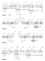
- Figure 1 The frame structure of orthogonal frequency division multiplex (OFDM) systems or conventional single carrier systems with frequency domain equalizer can be seen in Figure 1 .
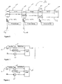
- Figure 2 an example of a block diagram of an OFDM systems is shown.
- the conventional single carrier wireless system with frequency domain equalizer uses cyclic prefix for carrier synchronization. Normally the coarse frame timing and channel estimation are realized by introducing the additional pilot frame and the frame adopts constant amplitude zero auto-correlation sequence (CAZAC).
- CAZAC constant amplitude zero auto-correlation sequence
- the present invention relates to a method for generating single carrier wireless communication signal, whereby said communication signal is based on a temporal frame structure, said frame structure comprising a guard interval and a data frame, said method comprising a step of inserting a cyclic prefix into said guard interval, said cyclic prefix comprising at least one pseudorandom-noise sequence.
- At least two of said pseudorandom-noise sequences are equal to each other.
- at least two of said pseudorandom-noise sequences are different to each other.
- said plurality of said pseudorandom-noise sequence is arranged symmetrically within the cyclic prefix.
- at least two of said pseudorandom-noise sequences are arranged alternatingly within the cyclic prefix.
- said at least one pseudorandom-noise sequence are consecutively arranged within the cyclic prefix.
- said cyclic prefix completely fills the guard interval.
- said cyclic prefix is a part of the guard interval.
- a remaining part of the guard interval is situated before and/or after said cyclic prefix.
- said remaining part of the guard interval comprises a sequence of zeros.
- at least one of said pseudorandom-noise sequences corresponds to a maximum length sequence.
- the present invention also relates to signal generator operable to generate single carrier wireless communication signal, whereby said communication signal is based on a temporal frame structure, said frame structure being operable to provide data management and comprising a guard interval and a data frame, said transmitter comprising a cyclic prefix insertion device operable to insert a cyclic prefix into said guard interval, said cyclic prefix comprising at least one pseudorandom-noise sequence.
- At least two of said pseudorandom-noise sequences are equal to each other.
- at least two of said pseudorandom-noise sequences are different to each other.
- said plurality of said pseudorandom-noise sequence is arranged symmetrically within the cyclic prefix.
- at least two of said pseudorandom-noise sequences are arranged alternatingly within the cyclic prefix.
- said at least one pseudorandom-noise sequence are consecutively arranged within the cyclic prefix.
- said cyclic prefix completely fills the guard interval.
- said cyclic prefix is a part of the guard interval.
- a remaining part of the guard interval is situated before and/or after said cyclic prefix.
- said remaining part of the guard interval comprises a sequence of zeros.
- at least one of said pseudorandom-noise sequences is a maximum length sequence.
- the present invention also relates to a method for processing a received single carrier wireless communication signal, whereby said communication signal is based on a temporal frame structure, said frame structure being operable to provide data management and comprising a guard interval and a data frame, whereby said guard interval comprises a cyclic prefix, said cyclic prefix comprising at least one pseudorandom-noise sequence, said method comprising the steps of correlating at least a part of said at least one pseudorandom-noise sequence of the cyclic prefix with at least one predetermined pseudorandom-noise sequence and outputting a correlation function.
- said method realizes coarse timing synchronization of said single carrier wireless communication signal based on said at least a part of said at least one pseudorandom noise sequence and/or on said correlation function.
- said coarse timing synchronization of said single carrier wireless communication signal is based on the autocorrelation peak of said correlation function.
- said method realizes channel estimation of said single carrier wireless communication signal based on said at least a part of said at least one pseudorandom noise sequence and/or on said correlation function.
- said method realizes carrier synchronization of said single carrier wireless communication signal based on said at least a part of said at least one pseudorandom noise sequence and/or on said correlation function.
- said carrier synchronization of said single carrier wireless communication signal is based on the spanned angle of two in-phase/quadrature constellation points of autocorrelation peaks of two consecutive cyclic prefixes.
- said carrier synchronization of said single carrier wireless communication signal is based on the phase difference rotation between said two constellation points and on the time interval between the autocorrelation peaks of said two pseudorandom-noise sequences of two consecutive cyclic prefixes.
- said method realizes signal-noise-ratio estimation of said single carrier wireless communication signal is based on said at least a part of said at least one pseudorandom noise sequence and/or on said correlation function.
- said signal-noise-ratio estimation of said single carrier wireless communication signal is based on the autocorrelation side-lobe of said correlation function, in case the correlation function comprises an auto-correlation side-lobe.
- said method realizes minimum mean-square error channel equalization of said single carrier wireless communication signal based on said at least a part of said at least one pseudorandom noise sequence and/or on said correlation function.
- said method comprises steps of applying Discrete Fourier Transformation to a channel transfer function in the time domain of said communication signal and/or of said correlation function and outputting a channel transfer function in the frequency domain, estimating signal-noise-ratio of said channel transfer function and/or of said correlation function, and applying Fast Fourier Transformation to said data frame.
- said method comprises steps of applying Fast Fourier Transformation to a channel transfer function in the time domain of said communication signal and/or of said correlation function and outputting a channel transfer function in the frequency domain, estimating signal-noise-ratio of said channel transfer function and/or of said correlation function, and applying Fast Fourier Transformation to said data frame.
- said method comprises a step of realising minimum mean-square error (MMSE) channel equalization by processing said channel transfer function in the frequency domain, said signal-noise-ratio and said Fast Fourier Transformation of said data frame.
- MMSE minimum mean-square error
- the present invention also relates to a signal processor operable to process a received single carrier wireless communication signal, whereby said communication signal is based on a temporal frame structure, said frame structure being operable to provide data management and comprising a guard interval and a data frame, said guard interval comprising a cyclic prefix, said cyclic prefix comprising at least one pseudorandom-noise sequence said receiver comprising a correlation device operable to correlate at least a part of said at least one pseudorandom-noise sequence of the cyclic prefix with at least one predetermined pseudorandom-noise sequence and to output a correlation function.
- said signal processor is operable to realize coarse timing synchronization of said single carrier wireless communication signal based on said at least a part of said at least one pseudorandom noise sequence and/or on said correlation function.
- said coarse timing synchronization of said single carrier wireless communication signal is based on the autocorrelation peak of said correlation function.
- said signal processor is operable to realize channel estimation of said single carrier wireless communication signal based on said at least a part of said at least one pseudorandom noise sequence and/or correlation function.
- said signal processor is operable to realize carrier synchronization of said single carrier wireless communication signal based on said at least a part of said at least one pseudorandom noise sequence and/or on said correlation function.
- said carrier synchronization of said single carrier wireless communication signal is based on the spanned angle of two in-phase/quadrature constellation points of autocorrelation peaks of two pseudorandom-noise sequences of two consecutive cyclic prefixes.
- said carrier synchronization of said single carrier wireless communication signal is based on the phase difference rotation between said two constellation points and on the time interval between the autocorrelation peaks of said two consecutive cyclic prefixes.
- said signal processor is operable to realize signal-noise-ratio estimation of said single carrier wireless communication signal based on said at least a part of said at least one pseudorandom noise sequence and/or on said correlation function.
- said signal-noise-ratio estimation of said single carrier wireless communication signal is based on the auto-correlation side-lobe of said correlation function, in case the correlation function comprises an auto-correlation side-lobe.
- said signal processor is operable to realize minimum mean-square error (MMSE) channel equalization of said single carrier wireless communication signal based on said at least a part of said at least one pseudorandom noise sequence and/or on said correlation function.
- MMSE minimum mean-square error
- said signal processor is operable to apply Discrete Fourier Transformation to a channel transfer function in the time domain of said communication signal and/or of said correlation function and to output a channel transfer function in the frequency domain, to estimate signal-noise-ratio of said channel transfer function and/or of said correlation function, and to apply Fast Fourier Transformation to said data frame.
- said signal processor is operable to apply Fast Fourier Transformation to a channel transfer function in the time domain of said communication signal and/or of said correlation function and to output a channel transfer function in the frequency domain, to estimate signal-noise-ratio of said channel transfer function and/or of said correlation function, and to apply Fast Fourier Transformation to said data frame.
- said signal processor is operable to realise minimum mean-square error (MMSE) channel equalization by processing said channel transfer function in the frequency domain, said signal-noise-ratio and said Fast Fourier Transformation of said data frame.
- MMSE minimum mean-square error
- This invention describes an application/management example of a frame structure for a single carrier system with frequency domain equalizer, whereby a M (maximum length) sequence 40b or a PN (pseudorandom noise) sequence is used as cyclic prefix in a guard interval 44b.
- Said frame structure is shown in Figure 4 .
- a M sequence can be exchanged by a PN sequence and vice-versa, when not mentioned otherwise.
- the cyclic prefix is able to cope with time dispersive multi-path fading channel, as long as the channel impulse response is shorter than the cyclic prefix. Otherwise there might be inter-frame interference.
- the introduced overhead is the same as or even less compared to the state of the art like conventional single carrier systems with frequency domain equalizer or OFDM systems.
- a PN sequence as a cyclic prefix is used to facilitate coarse timing, channel estimation and carrier synchronization for single carrier wireless systems using frequency domain equalizer.
- the channel estimation accuracy can be improved using a consecutive PN sequence.
- a PN sequence and a M sequence respectively, as well as their characteristics are explained below.
- a signal comprising a message unknown to a receiver has a random nature and is called stochastic signal.
- the receiver would be capable to reconstruct the message from the already sent signal due to the deterministic nature of the signal.
- a signal of deterministic character is a signal, which has a value x as a real number for every time t.
- a signal of stochastic character is a signal, which has a random number y for every time t, whereby said number y can be presented in a probability density function.
- a non-ideal auto-correlation function comprises several values more, whereby an almost ideal auto-correlation function of periodic consecutive function is presented in Figure 12 on the left graph and a non-ideal auto-correlation function is presented on the right graph.
- a PN sequence is a pseudo-random noise signal, which displays some deterministic features like periodic behaviour.
- a periodic cycle within the sequence can recur at least once. In case that the periodic cycle is as long as the PN sequence, meaning exactly one period cycle is available, said sequence is also defined as M sequence, standing for "maximum length sequence”.
- Figure 1 shows an example of a fram structure of OFDM systems or single carrier systems using frequency domain equalizer.
- One key principle of OFDM is that since low symbol rate modulation schemes (i.e. where the symbols are relatively long compared to the channel time characteristics) suffer less from intersymbol interference caused by multipath, it is advantageous to transmit a number of low-rate streams in parallel instead of a single high-rate stream. Since the duration of each symbol is long, it is feasible to insert a guard interval between the OFDM symbols, thus eliminating the intersymbol interference.
- the guard-interval also reduces the sensitivity to time synchronization problems.
- guard interval only contains redundant data, which means that it reduces the capacity
- OFDM-based systems such as some of the broadcasting systems, deliberately use a long guard interval in order to allow the transmitters to be spaced farther apart in a single frequency network (SFN), and longer guard intervals allow larger SFN cell-sizes.
- SFN single frequency network
- a rule of thumb for the maximum distance between transmitters in an SFN is equal to the distance a signal travels during the guard interval, for instance, a guard interval of 200 microseconds would allow transmitters to be spaced 60 km apart.
- This frame structure 13 of a OFDM system comprises three cyclic prefixes 10a, 10b, 10c and three data frames 12a, 12b, 12c and is shown in the time domain.
- the basic frame structure comprises one cyclic prefix and one data frame like 10a and 12a and can be chained successively.
- the cyclic prefixes 10a, 10b, 10c are embedded in the guard intervals 14a, 14b, 14c, respectively.
- a respective end 11a, 11b, 11c is designated, said ends 11a, 11b, 11c being part of the respective data frames 12a, 12b, 12c.
- a data frame is processed by a FFT (Fast Fourier Transformation), whereby the FFT window is as long as the data frame, said FFT window determining the time when said data is being processed by the system and/or the size of the data to be transformed by FFT step by step or at once.
- the cyclic prefix 10a is a repeat of the end of the symbol 11a which is placed at the beginning of said data frame 12a.
- Figure 2 shows an example of a block diagram of OFDM systems.
- Said OFDM system comprises a transmitter 33 and a receiver 34, whereby said transmitter 33 is operable to modulate and transmit electromagnetic waves which are orthogonal frequency division multiplexed, eventually.
- Said receiver 34 is operable to receive electromagnetic waves and also demodulate said waves which are orthogonal frequency division multiplexed.
- Said OFDM system is operable to establish a wireless connection and exchange data between its transmitter 33 and receiver 34.
- the transmitter 33 comprises a Quadrature amplitude modulation (QAM) modulator 20, an Inverse Fast Fourier Transformation (FFT) module 21, a Cyclic prefix insertion module 22, a Radio frequency transmitter 23 and an antenna 35.
- the QAM modulator 20 is connected to the Inverse FFT module 21, the Inverse FFT module 21 is connected to the Cyclic prefix insertion module 22, the Cyclic prefix insertion module 22 is connected to the Radio frequency transmitter 23 and the Radio frequency transmitter 23 is connected to the antenna 35.
- First an input signal to be modulated and transmitted is sent to the QAM modulator 20.
- the QAM modulator 20 is operable to modulate an input signal according to QAM.
- the Inverse FFT module 21 is operable to apply an inverse FFT transformation on the signal received from the QAM modulator 20.
- the Cyclic prefix insertion module 22 is operable to insert cyclic prefixes like 10a, 10b, 10c of Fig. 1 into the signal received from the Inverse FFT module 21.
- the Radio frequency transmitter 23 is operable to convert the signal received from the Cyclic prefix insertion module 22 into a signal which is transmittable by the antenna 35, said antenna 35 being operable to transmit electromagnetic waves carrying data based on said input data.
- the receiver 34 comprises an antenna 36, a Radio frequency receiver 24, a Remove cyclic prefix module 25, a FFT module 26, a Channel equalizer 27, a Channel estimation module 28 and a QAM demodulator 29.
- the antenna 36 is connected to the Radio frequency receiver 24, the Radio frequency receiver 24 is connected to the Remove cyclic prefix module 25, the Remove cyclic prefix module 25 is connected to the FFT module 26, the FFT module 26 is connected to both the Channel equalizer 27 and the Channel estimation module 28, the Channel estimation module 28 is additionally connected to the Channel equalizer 27 and the Channel equalizer 27 is eventually connected to the QAM demodulator 29.
- an output signal sent out by the QAM demodulator 29 can now be further processed.
- the antenna 36 is operable to receive the signal sent by the antenna 35 and convert said electromagnetic signal into an electric signal.
- the Radio frequency receiver 24 is operable to receive the electric signal from the antenna 36 and convert said signal into a baseband signal.
- the Remove cyclic prefix module 25 is operable to receive the signal from the Radio frequency receiver 24 and remove the inserted cyclic prefixes like e.g. 10a, 10b, 10c of Fig. 1 from said signal.
- the FFT module 26 is operable to transform the signal received from the Remove cyclic prefix module 25 according to a Fast Fourier Transformation.
- the Channel estimation module 28 is operable to receive the signal from the FFT module 26 and estimate the channel quality and other characteristics based on the channel, said channel corresponding to the wireless connection between the transmitter and the receiver.
- the channel quality might also describe the background and/or receiver noise.
- the Channel equalizer 27 is operable to receive one signal sent by the FFT module 26 and one signal sent by the Channel estimation module 28. Then the Channel equalizer 27 compensates for the dynamic frequency response of the wireless channel.
- the QAM demodulator 29 is operable to demodulate the signal sent by the Channel equalizer 27 and output a demodulated output signal.
- Figure 3 shows an example of a block diagram of single carrier systems using frequency domain equalizer.
- Said receiver 32 is operable to at least receive electromagnetic waves and also demodulate said waves which are modulated onto one single carrier.
- Said single carrier system is operable to establish a wireless connection and exchange data between its transmitter 31 and receiver 32.
- the transmitter 31 corresponds to the transmitter 33 shown in Fig. 2 .
- the receiver 32 corresponds to the receiver 34 shown in Fig. 2 and additionally comprises an Inverse FFT module 21, the function of said module 21 corresponding to the one described in Fig. 2 and being connected between the Channel equalizer 27 and the QAM demodulator 29 of said receiver 32.
- the signal from the Remove cyclic prefix module 25 is processed in the FFT module 26 step by step based on the size of the FFT frame.
- the FFT frame defines the time length, whereby a part of the signal is processed all at once by the FFT module 26.
- the cyclic prefix insertion module 22 is operable to insert M sequences or PN sequences into the frame structure, which is explained later in detail.
- the receiver 32 and the transmitter 31 could be part of one mobile wireless device. Moreover the receiver 32 and the transmitter 31 might be integrated in a semiconductor chip and comprise additional modules operable to extend the operability of the said receiver and/or transmitter, which are not shown in the Figure 3 for the sake of clarity.
- Figure 4 shows an example of a frame structure as an embodiment of the present invention.
- This frame structure 43 being an embodiment of the present invention comprises three cyclic prefixes 40a, 40b, 40c and three data frames 42a, 42b, 42c and is shown in the time domain.
- the cyclic prefixes are embedded in guard intervals 44a, 44b, 44c and completely filled in said intervals, said guard intervals 44a, 44b, 44c being the respective time periods before the data frame periods 42a, 42b, 42c.
- the cyclic prefix 40a, 40b, 40c comprises at least one PN sequence and is operable to provide data which is necessary for the management of the data frames during the transmission and reception of electro-magnetic waves carrying said data.
- FFT Fast Fourier Transformation
- the frame structure is different from Figure 1 , whereby only data frame is processed by a FFT. Since the cyclic prefix 40a is the same as the cyclic prefix 40b, based on the same principle of OFDM systems, the inter-frame interference introduced by the time disperse multi-path fading channel can be eliminated when the wireless channel delay is less then the length of cyclic prefix.
- the cyclic prefix 40a, 40b, 40c also helps the receiver 32 to correctly place the FFT frames and indicates the beginning of the respective data frames 42a, 42b, 42c being processed during a respective FFT frame if one PN sequence is used as 40a, 40b, 40c.
- the content of the cyclic prefixes 40a, 40b, 40c could be different, similar or equal to each other.
- the guard interval 44a, 44b, 44c is operable to provide guard time for propagation delay and to clearly separate the respective data frames 42a, 42b, 42c from each other, so the data of one data frame does not overlap with data of an adjacent data frame in case of multipath propagation during transmission.
- the data frame 42a, 42b, 42c is operable to provide data and/or information of any kind which is based on or corresponds to the content of a conversation like e.g. a phone call or other data meant to be transmitted and received by another communication participant. These data might comprise for example emails, pictures and the like.
- the data frames 42a, 42b, 42c are always of the same size, whereby their data does not necessarily fill out said data frames completely.
- the sequence or alternatively said the time flow of the frame structure starts with the first cyclic prefix 40a, continues with adjacent first data frame 42a, then the second cyclic prefix 40b, the second data frame 42b, the third cyclic prefix 40c and ends with the third data frame 42c.
- the frame structure is not limited to these three data frames and three cyclic prefixes, but can go on and form a chain of frames.
- a FFT frame whose operability was already explained in Figure 1 , might be as long as the combination of at least one data frame 42a, 42b, 42c and of at least one cyclic prefix 40a, 40b, 40c. This is different to Figure 1 , wherein one data frame is treated as one FFT frame.
- the FFT frame might comprise also a part of a preceding cyclic prefix, a complete succeeding data frame and a part of a succeeding cyclic prefix, like for example 40b, 42b and 40c. if for example, several similar PN sequences are concatenated and used as cyclic prefix. This means that the FFT frame can begin somewhere in the first cyclic prefix like 40a, covers the complete data frame 42a and ends somewhere in the succeeding cyclic prefix 40b. As a result, dynamic guard interval length can be achieved.
- the FFT frame and/or the time of the FFT frame itself might comprise at least one data frame and one cyclic prefix.
- the FFT frame might comprise one data frame and the two adjacent cyclic prefixes.
- adjacent FFT frames might either be situated side by side or they might overlap with each other. They could partially or completely overlap the area of the cyclic prefix and/or the guard interval, respectively, and/or each other, respectively.
- two separate FFT modules might be necessary to independently read and/or process said two FFT frames, respectively.
- the border between the two FFT frames might correspond with the border of the data frame and the guard interval or the border of the data frame and the cyclic prefix.
- the border is situated somewhere in the guard interval. In Figure 8 this embodiment is later explained in more detail.
- the cyclic prefix might comprise either a single PN sequence or a plurality of identical or different PN sequences, whereby said plurality of PN sequences is formed as a continuous string of sequences.
- said continuous string might comprise a random or a deterministic pattern based on how the PN sequences are arranged within the string.
- One pattern might comprise two different PN sequences which alternate within the cyclic prefix.
- the cyclic prefix comprises a symmetric arrangement of different PN sequences.
- the correlation of the cyclic prefix with a predetermined and/or controllable function comprising one or a plurality of identical or different PN sequences is performed in a receiver like 32 of Figure 3 , operable to receive the signal sent from the transmitter 31.
- the choice regarding the predetermined function and its amount and/or arrangement of PN sequences is dependent on the characteristics of the correlation of the cyclic prefix to be determined.
- Figure 5 shows an example of a frame structure as an embodiment of the present invention and the coarse frame timing and the carrier synchronization based on the auto-correlation peak of PN sequence.
- This frame structure 43 corresponds to the frame structure 43 shown in Fig. 4 and comprises four cyclic prefixes 40a, 40b, 40c, 40d and three data frames 42a, 42b, 42c, whereby said cyclic prefixes 40a, 40b, 40c, 40d are or comprises maximum length (M) sequences or pseudorandom noise (PN) sequences. Below each of these PN sequences 40a, 40b, 40c the correlation function of said PN sequences is shown as a graph 53a, 53b, 53c, respectively.
- M maximum length
- PN pseudorandom noise
- the correlation graphs 53a, 53b, 53c of the PN sequences comprises a high correlation peak and a low auto-correlation side-lobe, respectively, as later shown in Figure 11 .
- This auto-correlation function is created in a receiver, when the signal with the frame structure comprising the PN sequence is received and correlated with an identical PN sequence.
- the received cyclic prefix 40a comprises a plurality of identical PN sequences formed as a continuous string and is auto-correlated with one identical PN sequence at a receiver
- the auto-correlation graph of the PN sequence will comprise a plurality of high correlation peaks and low auto-correlation side-lobes.
- the cyclic prefix 40a comprises a plurality of PN sequences formed as a continuous string and is auto-correlated with one PN sequence being part of said string, it is possible to locate the exact position within the cyclic prefix, when the high correlation peak appears in the graph.
- a correlation sequence of identical or different PN sequences is used for correlating with said received cyclic prefix 40a, whereby said correlation sequence or a plurality of said correlation sequence are part of said received cyclic prefix 40a.
- the PN sequence is used to realize coarse timing, channel estimation carrier synchronization, obtain signal-noise-ratio (SNR) estimation and/or implement minimum mean-square error (MMSE) channel equalization.
- SNR signal-noise-ratio
- MMSE minimum mean-square error
- the FFT frame might start from the beginning or at the end of the graphs 53a, 53b, 53c. Also the high correlation peak or the low auto-correlation side-lobe might be the starting point of the FFT frame.
- the FFT frame which is already explained in Figure 4 , comprises at least the data frame succeeding the respective PN sequence. Alternatively the beginning of the FFT frame is independent from the cyclic prefix and/or the guard interval, but at least comprises the complete succeeding data frame.
- the coarse frame timing can be determined by the auto-correlation peak of the graph 53a, 53b, 53c of the PN sequence as shown in Figure 5 .
- the carrier synchronization can be implemented based on I/Q constellation rotation of the strongest auto-correlation peak from two nearby PN sequence. Below the correlation graphs 53a and 53b the respective constellation points 51 and 52 are shown in a Cartesian coordinates. The phase difference between these two constellation points and the time period between the two PN sequences 40a and 40b can be used for carrier synchronization.
- the I/Q constellation rotation is shown in detail in Figure 10 .
- the cyclic prefix might comprise at least one pseudorandom-noise sequence, whereby said one pseudorandom-noise sequence is complex value and comprises one 1-channel pseudorandom-noise sequence and one Q-channel pseudorandom-noise sequence.
- said I-channel sequence and the Q-channel sequence could either be the same or different to each other.
- the channel transfer function can be estimated based on several auto-correlation peaks of the graph 53a, 53b, 53c of the PN sequence, whereby the auto-correlation side-lobe from PN sequence can be used for signal to noise ratio (SNR) calculation.
- SNR signal to noise ratio
- the acquired information can be used for MMSE channel equalization.
- Figure 6 shows an apparatus for channel equalization being an additional part for an alternative embodiment of the present invention based on Fast Fourier Transformation (FFT).
- FFT Fast Fourier Transformation
- This apparatus comprises a FFT module 65, a SNR estimation module 62, a FFT module 63 and a MMSE channel equalization module 64, whereby said apparatus is operable for channel equalization.
- the channel equalization is mainly used in a receiver like 32 of Figure 3 .
- At least a part of said apparatus can be implemented into the receiver 32 of Fig. 3 as channel equalizer 27; in particular the MMSE channel equalizer 64 can be implemented as said equalizer 27.
- the FFT module 65 is operable to receive a signal which is a channel transfer function in the time domain, convert said signal into a channel transfer function in the frequency domain and output said signal.
- the SNR estimation module 62 is operable to receive the same channel transfer function in the time domain, which was received by the FFT module 65 and calculate and/or estimate the signal-noise-ratio of said function.
- the FFT module 63 is operable to receive a signal comprising the data frame and apply the FFT to said signal.
- the MMSE channel equalization module 64 is operable to receive the channel transfer function in the frequency domain provided by the FFT module 65, the SNR estimation signal provided by the SNR estimation module 62 and the signal provided by the FFT module 63 and eventually calculate and demodulate the output signal.
- the channel transfer function 53 comprises the PN sequence with a main high auto-correlation lobe and a smaller auto-correlation side-lobe.
- Figure 7 shows an apparatus for channel equalization being an additional part for an alternative embodiment of the present invention based on Discrete Fourier Transformation (DFT).
- DFT Discrete Fourier Transformation
- Figure 7 shows an apparatus for channel equalization being an additional part for an alternative embodiment of the present invention based on Discrete Fourier Transformation (DFT).
- DFT Discrete Fourier Transformation
- This apparatus comprises a Discrete Fourier Transformation (DFT) module 61, a SNR estimation module 62, a FFT module 63 and a MMSE channel equalization module 64, whereby said apparatus is operable for channel equalization.
- DFT Discrete Fourier Transformation
- the apparatus of Fig. 7 corresponds to the apparatus of Fig. 6 . Both apparatuses can be implemented into the receiver.
- the channel transfer function 53 comprises the PN sequence with a main high auto-correlation lobe and a smaller auto-correlation side-lobe.
- FFT can be used instead of DFT to reduce the calculation complexity for obtaining the channel transfer function from frequency domain, which will be adopted for channel equalization.
- Figure 8 shows an example of a frame structure with additional guard interval as an alternative embodiment of the present invention.
- This frame structure is based on the frame structure 43 shown in Fig. 4 and comprises three cyclic prefixes 80a, 80b, 80c and three data frames 82a, 82b, 82c, whereby said cyclic prefixes 80a, 80b, 80c are or comprise maximum length (M) sequences or pseudorandom noise (PN) sequences. Between each data frame 82a, 82b, 82c a respective guard interval 83a, 83b, 83c exists. In each of said guard intervals 83a, 83b, 83c a respective PN sequence 80a, 80b, 80c is embedded.
- M maximum length
- PN pseudorandom noise
- guard intervals 83a, 83b, 83c are in this embodiment larger than the PN sequences 80a, 80b, 80c, some free space is left on the right and left side of the PN sequences 80a, 80b, 80c.
- first free space 84a is located between the data frame 82a and the PN sequence 80b and the second free space 84b is located between the PN sequence 80b and the data frame 82b.
- guard interval 83a, 83b, 83c between the PN sequence and the data frame can be extended. If the length of guard interval 83a, 83b, 83c is longer than the wireless channel delay spread, there is no effect on the correlation peak from the data frame part and more accurate channel estimation can be obtained.
- the further guard interval between the PN sequence and the data frame meaning the first and/or second free space 84a and 84b can comprise a sequence of zeros.
- the two free spaces 84a and 84b might be of different or equal size, respectively.
- Figure 9 shows an example of a flow chart comprising a data timing recovery scheme as an alternative embodiment of the present invention.
- the flow chart is a timing offset compensation scheme and comprises nines steps S1 to S9, which is another way of the frequency-domain equalization with cyclic prefixes.
- the FFT frame comprises the data frame and the cyclic prefix as explained in Fig. 4 and is read out in step S1.
- a FFT is applied to the signal from S1, said signal comprising the FFT frame.
- a frequency-domain equalization is conducted to the signal received from step S2.
- an Inverse FFT is applied on the signal from S3.
- step S5 a decision is made based on the preceding steps whereby the (hard or soft) decision data is output.
- the data comprising the data frame and a part of the preceding and succeeding cyclic prefix is the result of step S5 and is finally determined and shown in step S6, respectively.
- the correlator After making the decision data output loop in step S7, the correlator searches and eventually determines the border of cyclic prefix and data by applying a PN sequence with said decision output for correlation in step S8 and finally the data part can be derived and shown in step S9.
- the timing of FFT frame meaning the beginning of said FFT frame, does not need to be on the exact place for every FFT frame, but can be placed individually within or on the borders of the cyclic prefix or guard interval as explained above.
- the timing offset change over the data frame becomes comparable with the data symbol length, because of the absolute value of clock offset.
- the timing offset can be adjusted finally.
- Figure 10 shows an example of a I/Q constellation rotation of the strongest auto-correlation peak from two nearby PN sequences.
- constellation points 51 a and 52a of two respective PN sequences shown in a complex plane of a coordinate system, also called constellation diagram. From the view of the origin of the coordinate system the two constellation points 51a and 52a envelop an angle ⁇ .
- the symbols are represented as complex numbers, they can be visualized as points on the complex plane.
- the real and imaginary axes are often called the inphase, or I-axis and the quadrature, or Q-axis. Plotting several symbols in a scatter diagram produces the constellation diagram.
- the points on a constellation diagram are called constellation points.
- the constellation points 51a and 52a are based on the constellation points 51 and 52 shown in Figure 5 .
- Figure 11 shows two examples of an auto-correlation graph of two signals.
- the graphs are shown in a grid system on the x-axis from -1,5 to 1,5 and on the y-axis from -0,4 to 1,0, whereby the vertical lines are spaced apart by 0,25 and the horizontal lines are spaced apart by 0,2. This values are normalized values and are not restricted to these values.
- the two signals creating the respective autocorrelation graphs can be PN sequences, whereby the resolution regarding the number of stages of the feed-back shift register is very high.
- Figure 12 shows two examples of an auto-correlation graph of a M sequence and a PN sequence
- the respective grid systems are based on the grid systems shown in Figure 11 , except for the fact that the vertical lines are spaced apart by 0, 5 and the horizontal lines are spaced apart by 0,2. Also both graphs show a symmetry at the axis of the ordinate.
- the left graph is the auto-correlation function of a M sequence.
- This correlation graph displays a periodic function which comprises a high peak value 54c and a lower value 57, and is thus similar to an ideal auto-correlation function of a random signal having only two values. Since the left graph comprises a plurality of identical M sequences, a plurality of identical peaks being spaced apart by a period length 58 of 1 are visible. In the case of M sequences the periodic intervals of the autocorrelation peaks equals the period length of the M sequence.
- the right graph is the auto-correlation function of a PN sequence.
- high peak values 54d are shown and are spaced apart from each other by a periodic interval 59, the values during said periodic interval 59 are not constant like in the left graph during the interval 58.
- Figure 13 shows an example of a guard interval and the arrangement of the cyclic prefix as well as of the PN-sequences.
- the guard interval 94 comprises a boarder 95a between the preceding data frame and itself as well as a boarder 95b between the succeeding data frame and itself. Moreover the guard interval comprises a cyclic prefix 90 and two free spaces 91 a and 91b. The first free space 91a is placed between the first boarder 95a and the cyclic prefix 90 and the second free space 91b is placed between the second boarder 95b and the cyclic prefix 90.
- the cyclic prefix comprises a symmetric axis 93 and eight PN-sequences 1 to 8 which are arranged consecutively.
- the unnumbered spaces at the edge and within the cyclic prefix 90 might comprise again a PN-sequence of the same length like e.g. PN-sequence 1.
- Figure 13 is basically describing the arrangement of said components.
- the cyclic prefix 90 comprises two different PN-sequences, which are arranged alternatingly, like e.g. one sequence is placed at the even positions 2, 4, 6, 8 and the other sequence is placed at the odd positions 1, 3, 5, 7.
- the cyclic prefix comprises different PN-sequences, which are arranged symmetrical. This means e.g. that one sequence is placed at position 4 and 5, the second sequence is placed at position 3 and 6, the next sequence is placed at position 2 and 7, and so on.
- the PN-sequences are not limited to be arranged consecutively but could comprise spaces between each other. These spaces might be filled with a sequence of zeros.
- guard interval 94 comprises two free spaces 91a and 91b before and after the cyclic prefix.
- the cyclic prefix 90 extends till the first boarder 95a and/or the second boarder 95b, so that only one or no free space exists.
- At least two of said pseudorandom-noise sequences are equal to each other or at least two of said pseudorandom-noise sequences are different to each other.
- at least two pseudorandom-noise sequences are arranged symmetrically within the cyclic prefix.
Landscapes
- Engineering & Computer Science (AREA)
- Power Engineering (AREA)
- Computer Networks & Wireless Communication (AREA)
- Signal Processing (AREA)
- Mobile Radio Communication Systems (AREA)
- Cable Transmission Systems, Equalization Of Radio And Reduction Of Echo (AREA)
Priority Applications (5)
| Application Number | Priority Date | Filing Date | Title |
|---|---|---|---|
| EP07006738A EP1976208B1 (de) | 2007-03-30 | 2007-03-30 | Drahtloses Einzelträger-Kommunikationssystem |
| EP11160770A EP2334020B1 (de) | 2007-03-30 | 2007-03-30 | Drahtloses Kommunikationssystem |
| US12/045,342 US8050339B2 (en) | 2007-03-30 | 2008-03-10 | Single carrier high rate wireless system |
| CN2008101003675A CN101282323B (zh) | 2007-03-30 | 2008-03-31 | 单载波高速率无线系统 |
| US13/238,961 US8526522B2 (en) | 2007-03-30 | 2011-09-21 | Single carrier high rate wireless system |
Applications Claiming Priority (1)
| Application Number | Priority Date | Filing Date | Title |
|---|---|---|---|
| EP07006738A EP1976208B1 (de) | 2007-03-30 | 2007-03-30 | Drahtloses Einzelträger-Kommunikationssystem |
Related Child Applications (1)
| Application Number | Title | Priority Date | Filing Date |
|---|---|---|---|
| EP11160770.1 Division-Into | 2011-04-01 |
Publications (2)
| Publication Number | Publication Date |
|---|---|
| EP1976208A1 true EP1976208A1 (de) | 2008-10-01 |
| EP1976208B1 EP1976208B1 (de) | 2011-05-25 |
Family
ID=38521121
Family Applications (2)
| Application Number | Title | Priority Date | Filing Date |
|---|---|---|---|
| EP07006738A Not-in-force EP1976208B1 (de) | 2007-03-30 | 2007-03-30 | Drahtloses Einzelträger-Kommunikationssystem |
| EP11160770A Ceased EP2334020B1 (de) | 2007-03-30 | 2007-03-30 | Drahtloses Kommunikationssystem |
Family Applications After (1)
| Application Number | Title | Priority Date | Filing Date |
|---|---|---|---|
| EP11160770A Ceased EP2334020B1 (de) | 2007-03-30 | 2007-03-30 | Drahtloses Kommunikationssystem |
Country Status (3)
| Country | Link |
|---|---|
| US (2) | US8050339B2 (de) |
| EP (2) | EP1976208B1 (de) |
| CN (1) | CN101282323B (de) |
Cited By (4)
| Publication number | Priority date | Publication date | Assignee | Title |
|---|---|---|---|---|
| EP2393223A1 (de) * | 2010-04-26 | 2011-12-07 | JDSU Deutschland GmbH | Inband-SNR-Messung auf Grundlage von spektraler Korrelation |
| EP2884709A1 (de) * | 2013-12-12 | 2015-06-17 | Vodafone GmbH | GFDM-Funkübertragung unter Verwendung einer kreisförmigen Pseudo-Präambel |
| US10477547B2 (en) | 2013-12-20 | 2019-11-12 | Zte Corporation | Ultra-large bandwidth data transmission method, device and computer storage medium |
| CN114884974A (zh) * | 2022-04-08 | 2022-08-09 | 海南车智易通信息技术有限公司 | 一种数据复用方法、系统及计算设备 |
Families Citing this family (41)
| Publication number | Priority date | Publication date | Assignee | Title |
|---|---|---|---|---|
| US7809046B2 (en) * | 2007-10-03 | 2010-10-05 | Agere Systems Inc. | Timing-offset estimation in modulated signals using weighted correlation values |
| EP2099187B1 (de) * | 2008-03-07 | 2011-05-25 | Sony Corporation | Funksystem mit neuartiger Präambel für einen Burst-Rahmen |
| US8325783B2 (en) * | 2008-09-23 | 2012-12-04 | Sprint Communications Company L.P. | Spreading code optimization based on quality factors |
| CN101729089B (zh) * | 2008-10-23 | 2013-07-10 | 弥亚微电子(上海)有限公司 | 通信系统的发射机、接收机及其同步方法 |
| CN101478510B (zh) * | 2009-02-17 | 2013-06-19 | 上海高清数字科技产业有限公司 | 一种自适应均衡器及使用该均衡器的接收机系统 |
| KR101283739B1 (ko) * | 2009-12-15 | 2013-07-08 | 한국전자통신연구원 | Ofdm 시스템에서의 주파수 옵셋 추정 방법 |
| US8401105B2 (en) | 2010-06-10 | 2013-03-19 | Intel Mobile Communications GmbH | Method for transmitting a data signal in a MIMO system |
| US9713019B2 (en) | 2011-08-17 | 2017-07-18 | CBF Networks, Inc. | Self organizing backhaul radio |
| US8502733B1 (en) | 2012-02-10 | 2013-08-06 | CBF Networks, Inc. | Transmit co-channel spectrum sharing |
| US9474080B2 (en) | 2011-08-17 | 2016-10-18 | CBF Networks, Inc. | Full duplex backhaul radio with interference measurement during a blanking interval |
| US9049611B2 (en) | 2011-08-17 | 2015-06-02 | CBF Networks, Inc. | Backhaul radio with extreme interference protection |
| US8982772B2 (en) | 2011-08-17 | 2015-03-17 | CBF Networks, Inc. | Radio transceiver with improved radar detection |
| US8761100B2 (en) | 2011-10-11 | 2014-06-24 | CBF Networks, Inc. | Intelligent backhaul system |
| US8467363B2 (en) | 2011-08-17 | 2013-06-18 | CBF Networks, Inc. | Intelligent backhaul radio and antenna system |
| US8422540B1 (en) | 2012-06-21 | 2013-04-16 | CBF Networks, Inc. | Intelligent backhaul radio with zero division duplexing |
| US10716111B2 (en) | 2011-08-17 | 2020-07-14 | Skyline Partners Technology Llc | Backhaul radio with adaptive beamforming and sample alignment |
| US10548132B2 (en) | 2011-08-17 | 2020-01-28 | Skyline Partners Technology Llc | Radio with antenna array and multiple RF bands |
| US10051643B2 (en) | 2011-08-17 | 2018-08-14 | Skyline Partners Technology Llc | Radio with interference measurement during a blanking interval |
| US10764891B2 (en) | 2011-08-17 | 2020-09-01 | Skyline Partners Technology Llc | Backhaul radio with advanced error recovery |
| US8385305B1 (en) | 2012-04-16 | 2013-02-26 | CBF Networks, Inc | Hybrid band intelligent backhaul radio |
| US8238318B1 (en) | 2011-08-17 | 2012-08-07 | CBF Networks, Inc. | Intelligent backhaul radio |
| US10708918B2 (en) | 2011-08-17 | 2020-07-07 | Skyline Partners Technology Llc | Electronic alignment using signature emissions for backhaul radios |
| US8989762B1 (en) | 2013-12-05 | 2015-03-24 | CBF Networks, Inc. | Advanced backhaul services |
| US8928542B2 (en) | 2011-08-17 | 2015-01-06 | CBF Networks, Inc. | Backhaul radio with an aperture-fed antenna assembly |
| USD704174S1 (en) | 2012-08-14 | 2014-05-06 | CBF Networks, Inc. | Intelligent backhaul radio with symmetric wing radome |
| CN103973398A (zh) * | 2013-01-31 | 2014-08-06 | 中兴通讯股份有限公司 | 数据发送、数据接收方法和装置 |
| CN106031063B (zh) * | 2014-02-13 | 2018-11-06 | 三星电子株式会社 | 发送设备、接收设备及其控制方法 |
| KR102337651B1 (ko) * | 2014-02-13 | 2021-12-10 | 삼성전자주식회사 | 송신 장치, 수신 장치 및 그 제어 방법 |
| CN104917706B (zh) * | 2014-03-10 | 2018-08-10 | 联想(北京)有限公司 | 一种信噪比估计方法及电子设备 |
| WO2016106936A1 (zh) * | 2014-12-31 | 2016-07-07 | 华为技术有限公司 | 一种数据传输方法、装置和系统 |
| CN104836767A (zh) * | 2015-04-13 | 2015-08-12 | 江苏技睿通信科技有限公司 | 一种可灵活配置保护间隔的毫米波室内通信系统 |
| WO2017007900A1 (en) | 2015-07-09 | 2017-01-12 | Idac Holdings, Inc. | Tail cancelation and addition of unique word for orthogonal frequency division multiplexing |
| CN108028826B (zh) * | 2015-10-16 | 2021-05-28 | 苹果公司 | 用于dms设计的装置或保护间隔的处理或零尾dft扩展ofdm系统 |
| CN106961598B (zh) | 2017-03-17 | 2019-02-12 | 浙江大华技术股份有限公司 | 一种信号制式判断方法及装置 |
| US10171127B2 (en) | 2017-05-19 | 2019-01-01 | Rohde & Schwarz Gmbh & Co. Kg | Method, system and computer program for synchronizing pseudorandom binary sequence modules |
| CN108881082B (zh) * | 2018-06-26 | 2019-09-24 | 中国人民解放军国防科技大学 | 信噪比确定方法及装置、信道均衡方法及装置 |
| EP3973679A4 (de) * | 2019-05-22 | 2022-05-04 | ZTE Corporation | Verfahren und vorrichtung zur einfügung einer dummy-sequenz in der datenmodulation |
| CN111935050B (zh) * | 2020-06-17 | 2022-07-05 | 中国船舶重工集团公司第七一五研究所 | 一种基于相位搜索的单载波频域均衡水声通信系统残余相偏修正方法 |
| US20230350006A1 (en) * | 2022-05-02 | 2023-11-02 | Qualcomm Incorporated | Radar reference signal for joint communication radar |
| CN117310647B (zh) * | 2023-11-28 | 2024-03-22 | 成都九洲迪飞科技有限责任公司 | 一种基于fpga的时域交叠目标识别信号快速分离方法 |
| CN120090905B (zh) * | 2025-02-28 | 2026-01-09 | 西安爱生技术集团有限公司 | 一种无人机集群频域均衡方法、设备、程序产品以及介质 |
Citations (10)
| Publication number | Priority date | Publication date | Assignee | Title |
|---|---|---|---|---|
| EP0730357A2 (de) * | 1995-03-01 | 1996-09-04 | Telia Ab | Synchronisierung von Frequenz und Rahmen für OFDM |
| EP1067709A1 (de) * | 1999-01-22 | 2001-01-10 | Mitsubishi Denki Kabushiki Kaisha | Adaptiver entzerrer und verfahren zur adaptiven entzerrung |
| EP1139621A2 (de) * | 2000-03-30 | 2001-10-04 | Hitachi Kokusai Electric Inc. | Digitaler empfänger mit automatischer Entzerrung |
| EP1202509A2 (de) | 2000-10-23 | 2002-05-02 | Oren Semiconductor Ltd. | Einstellungssignal für Einzelträgerübertragungn, sowie einstellung eines rekursiven Entzerrers |
| US6396866B1 (en) * | 1998-05-01 | 2002-05-28 | Trw Inc. | Symmetric chirp communications acquisition method and apparatus |
| US20040013084A1 (en) * | 2002-07-18 | 2004-01-22 | Motorola, Inc. | Training prefix modulation method and receiver |
| US6704344B1 (en) * | 1998-09-01 | 2004-03-09 | Univ Hong Kong | Broad-brand MPSK spread spectrum communications receiver with carrier recovery and tracking using correlation techniques |
| WO2004021657A2 (en) * | 2002-08-30 | 2004-03-11 | Koninklijke Philips Electronics N.V. | Frequency-domain equalization for single carrier signals |
| US20050122947A1 (en) * | 2003-12-09 | 2005-06-09 | Nokia Corporation | Direct-sequence CDMA method and device |
| WO2006075210A2 (en) | 2005-01-14 | 2006-07-20 | Nokia Corporation | System and method for utilizing different known guard intervals in single/multiple carrier communication systems |
Family Cites Families (8)
| Publication number | Priority date | Publication date | Assignee | Title |
|---|---|---|---|---|
| US7072289B1 (en) * | 2001-06-01 | 2006-07-04 | Lin Yang | Pseudo-random sequence padding in an OFDM modulation system |
| KR100852277B1 (ko) * | 2002-10-19 | 2008-08-18 | 삼성전자주식회사 | Ofdm 수신시스템의 동기획득시간을 단축시킬 수 있는ofdm 전송시스템 및 그 방법 |
| CN1283059C (zh) * | 2003-01-23 | 2006-11-01 | 上海贝尔阿尔卡特股份有限公司 | 一种载频同步的方法和装置 |
| US7519123B1 (en) * | 2004-04-08 | 2009-04-14 | Staccato Communications, Inc. | Spectral shaping for multiband OFDM transmitters with time spreading |
| KR20060008576A (ko) * | 2004-07-21 | 2006-01-27 | 삼성전자주식회사 | 기지 순환접두부호를 이용하여 적응적 변조를 수행하는다중 반송파 전송 시스템 및 방법 |
| US7724833B2 (en) * | 2006-07-25 | 2010-05-25 | Legend Silicon Corporation | Receiver for an LDPC based TDS-OFDM communication system |
| US8223625B2 (en) * | 2006-08-23 | 2012-07-17 | Qualcomm, Incorporated | Acquisition in frequency division multiple access systems |
| EP2099187B1 (de) | 2008-03-07 | 2011-05-25 | Sony Corporation | Funksystem mit neuartiger Präambel für einen Burst-Rahmen |
-
2007
- 2007-03-30 EP EP07006738A patent/EP1976208B1/de not_active Not-in-force
- 2007-03-30 EP EP11160770A patent/EP2334020B1/de not_active Ceased
-
2008
- 2008-03-10 US US12/045,342 patent/US8050339B2/en not_active Expired - Fee Related
- 2008-03-31 CN CN2008101003675A patent/CN101282323B/zh not_active Expired - Fee Related
-
2011
- 2011-09-21 US US13/238,961 patent/US8526522B2/en not_active Expired - Fee Related
Patent Citations (10)
| Publication number | Priority date | Publication date | Assignee | Title |
|---|---|---|---|---|
| EP0730357A2 (de) * | 1995-03-01 | 1996-09-04 | Telia Ab | Synchronisierung von Frequenz und Rahmen für OFDM |
| US6396866B1 (en) * | 1998-05-01 | 2002-05-28 | Trw Inc. | Symmetric chirp communications acquisition method and apparatus |
| US6704344B1 (en) * | 1998-09-01 | 2004-03-09 | Univ Hong Kong | Broad-brand MPSK spread spectrum communications receiver with carrier recovery and tracking using correlation techniques |
| EP1067709A1 (de) * | 1999-01-22 | 2001-01-10 | Mitsubishi Denki Kabushiki Kaisha | Adaptiver entzerrer und verfahren zur adaptiven entzerrung |
| EP1139621A2 (de) * | 2000-03-30 | 2001-10-04 | Hitachi Kokusai Electric Inc. | Digitaler empfänger mit automatischer Entzerrung |
| EP1202509A2 (de) | 2000-10-23 | 2002-05-02 | Oren Semiconductor Ltd. | Einstellungssignal für Einzelträgerübertragungn, sowie einstellung eines rekursiven Entzerrers |
| US20040013084A1 (en) * | 2002-07-18 | 2004-01-22 | Motorola, Inc. | Training prefix modulation method and receiver |
| WO2004021657A2 (en) * | 2002-08-30 | 2004-03-11 | Koninklijke Philips Electronics N.V. | Frequency-domain equalization for single carrier signals |
| US20050122947A1 (en) * | 2003-12-09 | 2005-06-09 | Nokia Corporation | Direct-sequence CDMA method and device |
| WO2006075210A2 (en) | 2005-01-14 | 2006-07-20 | Nokia Corporation | System and method for utilizing different known guard intervals in single/multiple carrier communication systems |
Non-Patent Citations (2)
| Title |
|---|
| BENVENUTO N ET AL: "On the Comparison Between OFDM and Single Carrier Modulation With a DFE Using a Frequency-domain Feedforward Filter", IEEE TRANSACTIONS ON COMMUNICATIONS, IEEE SERVICE CENTER, PISCATAWAY, NJ, US, vol. 50, no. 6, June 2002 (2002-06-01), pages 947 - 955, XP002995720, ISSN: 0090-6778 * |
| FALCONER D: "FREQUENCY DOMAIN EQUALIZATION FOR SINGLE-CARRIER BROADBAND WIRELESS SYSTEMS", IEEE COMMUNICATIONS MAGAZINE, IEEE SERVICE CENTER,NEW YORK, NY, US, vol. 40, no. 4, April 2002 (2002-04-01), pages 58 - 66, XP001102462, ISSN: 0163-6804 * |
Cited By (6)
| Publication number | Priority date | Publication date | Assignee | Title |
|---|---|---|---|---|
| EP2393223A1 (de) * | 2010-04-26 | 2011-12-07 | JDSU Deutschland GmbH | Inband-SNR-Messung auf Grundlage von spektraler Korrelation |
| EP2884709A1 (de) * | 2013-12-12 | 2015-06-17 | Vodafone GmbH | GFDM-Funkübertragung unter Verwendung einer kreisförmigen Pseudo-Präambel |
| US9236981B2 (en) | 2013-12-12 | 2016-01-12 | Vodafone Gmbh | GFDM radio transmission using a pseudo circular preamble |
| US10477547B2 (en) | 2013-12-20 | 2019-11-12 | Zte Corporation | Ultra-large bandwidth data transmission method, device and computer storage medium |
| CN114884974A (zh) * | 2022-04-08 | 2022-08-09 | 海南车智易通信息技术有限公司 | 一种数据复用方法、系统及计算设备 |
| CN114884974B (zh) * | 2022-04-08 | 2024-02-23 | 海南车智易通信息技术有限公司 | 一种数据复用方法、系统及计算设备 |
Also Published As
| Publication number | Publication date |
|---|---|
| US8050339B2 (en) | 2011-11-01 |
| US20120008709A1 (en) | 2012-01-12 |
| CN101282323A (zh) | 2008-10-08 |
| EP2334020A1 (de) | 2011-06-15 |
| US20080240307A1 (en) | 2008-10-02 |
| EP1976208B1 (de) | 2011-05-25 |
| US8526522B2 (en) | 2013-09-03 |
| EP2334020B1 (de) | 2013-03-06 |
| CN101282323B (zh) | 2013-12-11 |
Similar Documents
| Publication | Publication Date | Title |
|---|---|---|
| US8526522B2 (en) | Single carrier high rate wireless system | |
| EP2099187B1 (de) | Funksystem mit neuartiger Präambel für einen Burst-Rahmen | |
| Bolcskei | Blind estimation of symbol timing and carrier frequency offset in wireless OFDM systems | |
| JP5201739B2 (ja) | 送信方法、送信装置、受信方法及び受信装置 | |
| CN115486037B (zh) | 包括循环移位正交基函数的信号的生成和接收 | |
| CN101682454B (zh) | 发射和接收多载波扩频信号的方法,发射和接收设备 | |
| CN1980217A (zh) | 发送方法、接收方法、发送装置、接收装置 | |
| KR20110005748A (ko) | 무선 통신 시스템에서 파일럿 다중화를 위한 방법 및 장치 | |
| US7995664B2 (en) | Method and apparatus for transmitting pilot symbols in wireless communication system | |
| KR100849338B1 (ko) | 직교주파수분할다중 방식의 이동통신시스템에서시공간-주파수 부호화/복호화 장치 및 방법 | |
| US7120201B2 (en) | Method and system for optimization of channel estimation and synchronization in an OFDM-MIMO wireless communication system | |
| Karpovich et al. | Random-padded OTFS modulation for joint communication and radar/sensing systems | |
| Ma et al. | Iterative channel estimation for OTFS using ZC sequence with low peak-to-average power ratio | |
| CN105516031A (zh) | 一种快跳频系统的信道估计和信道均衡方法 | |
| JPH11275047A (ja) | 送信機、受信機および伝送方法 | |
| JP2006033083A (ja) | Ofdm伝送システム。 | |
| CN100521554C (zh) | 基于二值全通序列保护间隔填充的频域信道估计方法 | |
| WO2012035345A2 (en) | Improvements in ofdm communication systems | |
| Nasraoui | Advanced Synchronization Techniques for OFDM Systems | |
| Ribeiro et al. | An OFDM Symbol Design for Reduced Complexity MMSE Channel Estimation. | |
| EP3076627A1 (de) | Übertragungsdiversität von orthogonalem entwurf für fbmc/oqam | |
| Berggren et al. | Waveform based on ZAC sequences | |
| Wang et al. | EM-based adaptive frequency domain estimation of Doppler shifts with CRLB analysis for CDMA systems | |
| Ranasinghe et al. | Low-Complexity Receiver Design for Affine Filter Bank Modulation | |
| EP2077625B1 (de) | Abgestimmter Filter und Empfänger |
Legal Events
| Date | Code | Title | Description |
|---|---|---|---|
| PUAI | Public reference made under article 153(3) epc to a published international application that has entered the european phase |
Free format text: ORIGINAL CODE: 0009012 |
|
| AK | Designated contracting states |
Kind code of ref document: A1 Designated state(s): AT BE BG CH CY CZ DE DK EE ES FI FR GB GR HU IE IS IT LI LT LU LV MC MT NL PL PT RO SE SI SK TR |
|
| AX | Request for extension of the european patent |
Extension state: AL BA HR MK RS |
|
| 17P | Request for examination filed |
Effective date: 20090302 |
|
| 17Q | First examination report despatched |
Effective date: 20090422 |
|
| AKX | Designation fees paid |
Designated state(s): DE FR GB |
|
| GRAP | Despatch of communication of intention to grant a patent |
Free format text: ORIGINAL CODE: EPIDOSNIGR1 |
|
| GRAS | Grant fee paid |
Free format text: ORIGINAL CODE: EPIDOSNIGR3 |
|
| GRAA | (expected) grant |
Free format text: ORIGINAL CODE: 0009210 |
|
| AK | Designated contracting states |
Kind code of ref document: B1 Designated state(s): DE FR GB |
|
| REG | Reference to a national code |
Ref country code: GB Ref legal event code: FG4D |
|
| REG | Reference to a national code |
Ref country code: DE Ref legal event code: R096 Ref document number: 602007014815 Country of ref document: DE Effective date: 20110707 |
|
| PLBE | No opposition filed within time limit |
Free format text: ORIGINAL CODE: 0009261 |
|
| STAA | Information on the status of an ep patent application or granted ep patent |
Free format text: STATUS: NO OPPOSITION FILED WITHIN TIME LIMIT |
|
| 26N | No opposition filed |
Effective date: 20120228 |
|
| REG | Reference to a national code |
Ref country code: DE Ref legal event code: R097 Ref document number: 602007014815 Country of ref document: DE Effective date: 20120228 |
|
| PGFP | Annual fee paid to national office [announced via postgrant information from national office to epo] |
Ref country code: FR Payment date: 20140319 Year of fee payment: 8 |
|
| PGFP | Annual fee paid to national office [announced via postgrant information from national office to epo] |
Ref country code: GB Payment date: 20140319 Year of fee payment: 8 |
|
| GBPC | Gb: european patent ceased through non-payment of renewal fee |
Effective date: 20150330 |
|
| REG | Reference to a national code |
Ref country code: FR Ref legal event code: ST Effective date: 20151130 |
|
| PG25 | Lapsed in a contracting state [announced via postgrant information from national office to epo] |
Ref country code: GB Free format text: LAPSE BECAUSE OF NON-PAYMENT OF DUE FEES Effective date: 20150330 |
|
| PG25 | Lapsed in a contracting state [announced via postgrant information from national office to epo] |
Ref country code: FR Free format text: LAPSE BECAUSE OF NON-PAYMENT OF DUE FEES Effective date: 20150331 |
|
| REG | Reference to a national code |
Ref country code: DE Ref legal event code: R084 Ref document number: 602007014815 Country of ref document: DE |
|
| PGFP | Annual fee paid to national office [announced via postgrant information from national office to epo] |
Ref country code: DE Payment date: 20210217 Year of fee payment: 15 |
|
| REG | Reference to a national code |
Ref country code: DE Ref legal event code: R119 Ref document number: 602007014815 Country of ref document: DE |
|
| PG25 | Lapsed in a contracting state [announced via postgrant information from national office to epo] |
Ref country code: DE Free format text: LAPSE BECAUSE OF NON-PAYMENT OF DUE FEES Effective date: 20221001 |