EP1976363A1 - Vorrichtung an einer Maschine zur Montage von Bauteilen - Google Patents
Vorrichtung an einer Maschine zur Montage von Bauteilen Download PDFInfo
- Publication number
- EP1976363A1 EP1976363A1 EP07105338A EP07105338A EP1976363A1 EP 1976363 A1 EP1976363 A1 EP 1976363A1 EP 07105338 A EP07105338 A EP 07105338A EP 07105338 A EP07105338 A EP 07105338A EP 1976363 A1 EP1976363 A1 EP 1976363A1
- Authority
- EP
- European Patent Office
- Prior art keywords
- component
- receiver
- magazine
- holding means
- picking
- Prior art date
- Legal status (The legal status is an assumption and is not a legal conclusion. Google has not performed a legal analysis and makes no representation as to the accuracy of the status listed.)
- Withdrawn
Links
- 239000000758 substrate Substances 0.000 description 4
- 238000006073 displacement reaction Methods 0.000 description 3
- 238000000034 method Methods 0.000 description 2
- 230000006978 adaptation Effects 0.000 description 1
- 238000004519 manufacturing process Methods 0.000 description 1
- 238000012986 modification Methods 0.000 description 1
- 230000004048 modification Effects 0.000 description 1
- 210000002105 tongue Anatomy 0.000 description 1
- 230000007704 transition Effects 0.000 description 1
Images



Classifications
-
- H—ELECTRICITY
- H05—ELECTRIC TECHNIQUES NOT OTHERWISE PROVIDED FOR
- H05K—PRINTED CIRCUITS; CASINGS OR CONSTRUCTIONAL DETAILS OF ELECTRIC APPARATUS; MANUFACTURE OF ASSEMBLAGES OF ELECTRICAL COMPONENTS
- H05K13/00—Apparatus or processes specially adapted for manufacturing or adjusting assemblages of electric components
- H05K13/02—Feeding of components
- H05K13/028—Simultaneously loading a plurality of loose objects, e.g. by means of vibrations, pressure differences, magnetic fields
-
- H—ELECTRICITY
- H05—ELECTRIC TECHNIQUES NOT OTHERWISE PROVIDED FOR
- H05K—PRINTED CIRCUITS; CASINGS OR CONSTRUCTIONAL DETAILS OF ELECTRIC APPARATUS; MANUFACTURE OF ASSEMBLAGES OF ELECTRICAL COMPONENTS
- H05K13/00—Apparatus or processes specially adapted for manufacturing or adjusting assemblages of electric components
- H05K13/04—Mounting of components, e.g. of leadless components
- H05K13/043—Feeding one by one by other means than belts
- H05K13/0434—Feeding one by one by other means than belts with containers
Definitions
- the present invention relates to a component magazine for a component mounting machine.
- One type of component mounting machines uses components consecutively stored in elongate plastic tubes.
- the tubes are loaded in a vibrating magazine, such as for example VMF30 manufactured by MYDATA AB.
- the components within the tubes are moved forward by vibrating the magazine both longitudinally and vertically thereof.
- Each tube has been mounted in the magazine in such a way that a forward end thereof abuts against a stop at a component receiver.
- the component receiver serves in providing a stop for the forward movement of the components, and in providing a well defined picking position.
- the position of the component receiver determines the picking position for the component in the tube, and the position of the component receiver is adjustable by means of a fastening screw, which extends through a slit of the component receiver into a fixed seat in a base. When the screw is slightly loosened the component receiver is displaceable along the slit relative to the screw.
- a picking head is arranged on an X wagon, which is movable along an X axis.
- a substrate, on which the components are going to be mounted, is arranged on a Y wagon, which is movable along a Y axis, extending perpendicular to the X axis.
- Component mounting machines demand that a component which is to be picked has a well defined position, known to the machine in advance. Components which have such a well defined position known by the software of the machine are called located components, or components having located picking positions.
- a manual locating operation is performed as follows.
- the component mounting machine comprises a camera or some other vision device, which is mounted on the X wagon, and which is used by the machine during the mounting procedure. For each tube, an operator, looking at the image generated by the camera, moves the camera to the picking position of the component that is received by the component receiver. The operator indicates the picking position to the machine software. This operation often includes a position adjustment of the component receiver as well, in order to align the component with a desired picking position.
- This conventional manual locating operation is time consuming, and has to be repeated if the magazine is removed from the machine and loaded into another machine or is reloaded into the same machine. This is due to various tolerances between different parts at interfaces between them.
- a component magazine for a component mounting machine which component magazine comprises a lower part including a feeding device, and an upper part including a tube holder.
- the upper part is mounted at said lower part, and is reciprocatingly movable along said lower part by means of said feeding device.
- the upper part is provided with at least one fiducial mark, and has a component reception portion where components are received from tubes and aligned in a picking position.
- the component reception portion is provided with a component receiver holding means having a fixed position in relation to said at least one fiducial mark, and at least one component receiver, which is/are fastened at the component receiver holding means, and which define at least one respective picking position for the components on said component reception portion.
- the machine vision system can be used for detecting the fiducial mark(s) and adjusting the position of the upper part in accordance with the fiducial mark(s). Having, thus, positioned the upper part, the component receiver holding means is automatically positioned, since it has a fixed position relative to the fiducial mark(s). It should be noted that in the description of embodiments below only embodiments having two fiducial marks are shown and described. However, as evident from the claims, the object of the invention is achieved with merely one fiducial mark.
- each respective component receiver comprises a component positioning surface, which is arranged at a predetermined fixed position relative to the component receiver holding means at which it is fastened, thereby providing a predetermined fixed picking position.
- a very small tolerance is obtained for the final picking position, which can be said to be a default position.
- the component receivers are adjustably mounted at the holding means. Then, an initial manual adjustment may be needed, while a good repeatability is obtained due to the fiducial mark, or marks. That is, if the magazine is unloaded from the machine, no manual adjustment will be required at reloading.
- each respective component receiver has a snap-in socket, by which it is attached to the component receiver holding means.
- the component receiver holding means is rigidly connected with the at least one fiducial mark. Consequently, the picking position is well defined, possibly except for a minimal tolerance generated at production of the upper part of the magazine. That tolerance, as is evident to a skilled person, is negligible in this context.
- the upper part is demountable from the lower part. Due to the fiducial mark(s) there is no need for any manual adjustment when remounting an upper part that has been demounted.
- An embodiment of a component magazine 101 according to the present invention has two main parts, a lower part 103, and an upper part 105, which is demountably connected with the lower part 103.
- the upper part 105 will be referred to as a pallet 105.
- the lower part 103 is provided with a feeding device 107 having front and rear carrier members 109, 111 for carrying the pallet 105.
- the pallet 105 comprises a base plate 110 and is provided with front and rear engagement portions 113, 115, arranged at a bottom side of the base plate 110, which are engaged with the respective carrier members 109, 111.
- the engagement portions 113, 115 are demountable from the carrier members 109, 111.
- the feeding device 107 is of a type which per se is well known to a person skilled in the art, and therefore it is not illustrated in detail. In short the feeding device 107 includes a motor which moves the front carrier member 109, and thus the pallet 105, reciprocatingly in a way that moves the components forward.
- the rear carrier member 111 is a mere slide plate, on top of which the rear engagement portion 115 slides back and forth.
- the reciprocating movement is fast, and to an observer it looks like the pallet 105 vibrates. Therefore vibration is a term that will be used in addition below.
- the pallet 105 is a support for tubes holding components, which are to be mounted.
- the tubes are fed along the top surface 117 of the base plate 110 from a first end 116 of the pallet 105 towards a second end 118 thereof past two tube holders bars 119, 121, fixed as two arcs across the base plate 110, into abutment against component receivers 120 mounted at a component reception portion 124 of the pallet 105 close to the second end 118 thereof.
- Each tube holder bar 119, 121 is provided with a plurality, here 16, of tube holders 123, 125.
- the tube holders 123, 125 are sloping from the respective bar 119, 121 towards, and are prestressed against, the top surface 117.
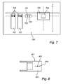
- a typical kind of component mounting machine 700 employing the present invention would be a so called split-axis machine having an X wagon 701, which is movable in an X direction and a Y wagon 703, which is movable in a Y direction perpendicular to the X direction.
- the X wagon 701 carries a component picking head 706 as well as a vision means, such as a camera, 702 for locating the component to be picked.
- the wagons and their associated parts are only shown most schematic, since they are per se well known.
- the Y wagon 703 carries the substrate 704, such as for example a PCB (Printed Circuit Board), on which the components 705 provided by the component magazines 707 are to be mounted.
- PCB Print Circuit Board
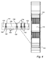
- fiducial marks embodied as two dots 122 in the present embodiment, as illustrated in Fig. 4 .
- a component reception portion 124 which constitutes a portion of the pallet 105, is shown.
- the fiducial marks 122 are provided within the component reception portion 124 at opposite sides of the base plate 110, and thus of the pallet 105, and indicate a picking position line 126 extending straight between the fiducial marks 122.
- a component receiver holding means here embodied as component receiver holders 145, which each has a fixed position in relation to the fiducial marks 122, is arranged at the component reception portion 124.
- the component receiver holders 145 are threaded holes arranged along a straight line in parallel with and at a small distance from the picking position line 126. The holes 145 are displaced towards the second end 118 in relation to the picking position line 126. Since the fiducial marks 122 and the component receiver holders 145 are integral with the base plate 110, the component receiver holders 145 are rigidly connected with the fiducial marks 122.
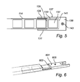
- Component receivers 120 are fixed to the component receiver holding means, i.e. the component receiver holders 145. By having the screw fastening according to these embodiments the component receivers 120 as well are arranged at predetermined exact positions relative to the fiducial marks 122. The component receivers are arranged to receive a tube 114 each.
- the component receiver 127 is fork shaped.
- the fork has two protruding guide pins 129, 131 between which the tube 114 is received, guided thereby.
- An inner portion of the space between the guide pins is provided with a bottom plate 133.
- the guide pins 129, 131 and the bottom plate 133 protrude from a rear portion, or fastening portion, 139 of the fork 127.
- the thickness of the bottom plate 133 is a fraction of the thickness of the fastening portion 139.
- the fastening portion 139 comprises a component receiver fastener 143, which in this embodiment is embodied by a screw extending through the fastening portion 139 and a bit further downwards.
- the pallet 105 comprises component receiver holders 145, in this embodiment screw holes 145.
- the screw 143 is fastened into the screw hole 145.
- the component receiver fasteners are snap-in fasteners, which are snap-in locked to the component receiver holding means, as will be further described below.
- the component receiver 601 is turned back to front, and has a straight front edge 603, which is the rear edge when turned the right way, that serves as a stop for the tube 114.
- a straight front edge 603 which is the rear edge when turned the right way, that serves as a stop for the tube 114.
- the component receiver 601 has a screw fastener 605.
- the front edge 603 of the block 601 additionally serves as a component positioning surface.
- a further component receiver 801 has an adjustable fastening position, such as by having the screw 803 extending through an elongate slit 805 formed in the fastening portion 807 of the component receiver 801, similar to the slit of the previous embodiment.
- Such a component receiver 801 is disadvantageous in that often the automatic locating operation is no longer possible to perform, but a manual adjustment of the component receivers will be necessary.
- this will still be advantageous, since the manual operation will only have to be performed once, when the magazine, or the pallet, is loaded for the first time at the component mounting machine. Then, if the pallet is temporarily removed and put back or moved to another magazine, or the like, due to the fiducial marks and the Y directional adjustability of the pallet, there will be no need for any additional manual adjustment.
- the component receivers are provided with a snap-in fastener, as shown in Fig. 9 .
- the pallet 901 having a bottom plate 903 and elongate side walls 905, is provided with a component receiver holding means embodied as a single rail shaped holder, or simply rail, 907 extending straight across the bottom plate 903 between the side walls 905 close to a front end of the pallet 901.
- a component receiver holding means embodied as a single rail shaped holder, or simply rail, 907 extending straight across the bottom plate 903 between the side walls 905 close to a front end of the pallet 901.
- fiducial marks 913 are oppositely arranged on a respective narrow top surface of the side walls 905, one mark 913 at each side wall 905.
- the component receivers 909 are each provided with a snap lock portion 911.
- the snap lock portion 911 engages with the rail 907, thereby locking the position of the component receiver 909.
- the receiving portion of the component receiver is arranged at a fixed distance from the snap lock portion 911, and this distance is accurately matched with the longitudinal distance between the rail 907 and the fiducial marks 913, such that the picking position of a component received by the component receiver 909 is aligned with a picking position line between the fiducial marks 913.
- the component receiver is provided with picking position markers 915, embodied as transverse lines on a top side of the component receiver 909 aligned with a centre position of a received component.
- the component receiver 1001 is provided with a snap lock pin 1003, which protrudes downwards from the bottom of the component receiver 1001.
- the snap lock pin 1003 has resilient tongues 1004 which are arranged to be received in a recess 1011 of the bottom plate 1009 of the pallet, which recess 1011 constitutes a component receiver holding means.
- the manual locating of components can be avoided, and replaced by an automatic locating operation as follows.
- the machine 700 moves the X wagon 701 until it reaches a first magazine 707.
- the camera 702 detects the fiducial marks 122 on the pallet 105, and image processing software determines any displacement of the picking head 706 from the desired picking line 126. If a correction is necessary, the machine 700 adjusts the pallet 105 by controlling the motor of the feeding device 107 to perform minor movements of the pallet 105 along the Y direction. Then, if one of the kinds of component receivers providing default picking positions are used, the machine is ready for the very component mounting operation.
- the invention is not limited to this type of machine.
- a component mounting machine in which the picking head is movable in both X and Y directions while the substrate is fixed during the component placement procedure.
- Such mounting machines are generally so called gantry machines, in which the picking head is mounted on a gantry and movable along the gantry in the X direction, which gantry is in turn movable in the Y direction, or vice versa.
- the machine will adjust the position of the gantry and/or picking head instead of the pallet, after detecting the fiducial marks on the pallet.
- the component magazines are provided with tubes and loaded to the component mounting machine in similar manner as described above, and an automatic locating operation is initiated. Then, the machine moves the gantry and picking head until a first magazine is reached. A camera detects fiducial marks on the pallet, and image processing software determines any displacement of the picking head from a desired picking line. If a correction is required, the machine then adjusts the gantry and/or the picking head, resulting in minor movements of the picking head along the Y direction in adaptation to the determined displacement, in preparation for an ensuing component mounting operation.
Landscapes
- Engineering & Computer Science (AREA)
- Manufacturing & Machinery (AREA)
- Microelectronics & Electronic Packaging (AREA)
- Supply And Installment Of Electrical Components (AREA)
Priority Applications (2)
| Application Number | Priority Date | Filing Date | Title |
|---|---|---|---|
| EP07105338A EP1976363A1 (de) | 2007-03-30 | 2007-03-30 | Vorrichtung an einer Maschine zur Montage von Bauteilen |
| PCT/SE2008/050352 WO2008121061A1 (en) | 2007-03-30 | 2008-03-28 | A component magazine for a component mounting machine |
Applications Claiming Priority (1)
| Application Number | Priority Date | Filing Date | Title |
|---|---|---|---|
| EP07105338A EP1976363A1 (de) | 2007-03-30 | 2007-03-30 | Vorrichtung an einer Maschine zur Montage von Bauteilen |
Publications (1)
| Publication Number | Publication Date |
|---|---|
| EP1976363A1 true EP1976363A1 (de) | 2008-10-01 |
Family
ID=38458221
Family Applications (1)
| Application Number | Title | Priority Date | Filing Date |
|---|---|---|---|
| EP07105338A Withdrawn EP1976363A1 (de) | 2007-03-30 | 2007-03-30 | Vorrichtung an einer Maschine zur Montage von Bauteilen |
Country Status (2)
| Country | Link |
|---|---|
| EP (1) | EP1976363A1 (de) |
| WO (1) | WO2008121061A1 (de) |
Citations (3)
| Publication number | Priority date | Publication date | Assignee | Title |
|---|---|---|---|---|
| US5828310A (en) * | 1997-05-20 | 1998-10-27 | Motorola, Inc. | Indicator system having plurality of feeders and actuators arranged to selectively actuate a sensor |
| US6062797A (en) * | 1994-10-11 | 2000-05-16 | Us Vibra Inc. | Top platform and interchangeable guide lane assemblage for vibratory feeders |
| EP1482775A2 (de) * | 2003-05-23 | 2004-12-01 | Hitachi High-Tech Instruments Co., Ltd. | Verfahren zur Montage von elektronischen Bauteilen |
Family Cites Families (3)
| Publication number | Priority date | Publication date | Assignee | Title |
|---|---|---|---|---|
| US4500246A (en) * | 1983-03-01 | 1985-02-19 | Universal Instruments Corporation | Indexed feed of electronic component supply tubes |
| MY103662A (en) * | 1988-01-28 | 1993-08-28 | Emhart Ind | Method of setting up apparatus for handling electrical or electronic components |
| US6209295B1 (en) * | 1999-04-23 | 2001-04-03 | Advanced Micro Devices, Inc. | Plastic and metal tube holder for SOIC package |
-
2007
- 2007-03-30 EP EP07105338A patent/EP1976363A1/de not_active Withdrawn
-
2008
- 2008-03-28 WO PCT/SE2008/050352 patent/WO2008121061A1/en not_active Ceased
Patent Citations (3)
| Publication number | Priority date | Publication date | Assignee | Title |
|---|---|---|---|---|
| US6062797A (en) * | 1994-10-11 | 2000-05-16 | Us Vibra Inc. | Top platform and interchangeable guide lane assemblage for vibratory feeders |
| US5828310A (en) * | 1997-05-20 | 1998-10-27 | Motorola, Inc. | Indicator system having plurality of feeders and actuators arranged to selectively actuate a sensor |
| EP1482775A2 (de) * | 2003-05-23 | 2004-12-01 | Hitachi High-Tech Instruments Co., Ltd. | Verfahren zur Montage von elektronischen Bauteilen |
Also Published As
| Publication number | Publication date |
|---|---|
| WO2008121061A1 (en) | 2008-10-09 |
Similar Documents
| Publication | Publication Date | Title |
|---|---|---|
| US7568284B2 (en) | Components insertion method | |
| US5588614A (en) | Electronic-component supplying cartridge | |
| EP1231828B1 (de) | Bauteilbestückungsvorrichtung und verfahren | |
| CN108480134B (zh) | 一种点胶针头自动定位装置及定位方法 | |
| EP1018862A1 (de) | Vorrichtung und verfahren zur bestueckung von bauteilen | |
| JP5779386B2 (ja) | 電気部品装着機 | |
| AU1354692A (en) | Registration system | |
| US10117368B2 (en) | Board work device | |
| CN102958342B (zh) | 电子部件自动供给装置以及电子部件安装装置 | |
| JP2016152245A (ja) | 電子部品実装装置及び電子部品実装方法 | |
| JPH0866837A (ja) | 位置合わせ装置および位置合わせ方法 | |
| EP1976363A1 (de) | Vorrichtung an einer Maschine zur Montage von Bauteilen | |
| US8234779B2 (en) | Arrangement and system at a component mounting machine | |
| JPH10335889A (ja) | 電子部品収納用パレットの位置決め方法および位置補 正方法 | |
| US6446331B1 (en) | Mounting apparatus of electronic components and mounting methods of the same | |
| EP3654747B1 (de) | Einstellungsvorrichtung und ausrichtungsverfahren | |
| US12453068B2 (en) | Mounting tool for a component mounting machine | |
| JP4973842B2 (ja) | 液滴塗布装置及び方法 | |
| US11006560B2 (en) | Method of manufacturing component-mounted substrate | |
| KR101518775B1 (ko) | 캐리어 테이프 피더의 멀티 교정 장치 | |
| JP2013219131A (ja) | 吸着ノズルの取り付け方法、部品実装方法及び部品実装装置 | |
| JP2021133619A (ja) | 印刷装置 | |
| EP3322273B1 (de) | Komponentenmontagevorrichtung | |
| EP2448391A2 (de) | Positioniervorrichtung für einen PCB-Einführstift, Verfahren und Vorrichtung zum Einführen des Stifts in PCB | |
| JP7344368B2 (ja) | 対基板作業機 |
Legal Events
| Date | Code | Title | Description |
|---|---|---|---|
| PUAI | Public reference made under article 153(3) epc to a published international application that has entered the european phase |
Free format text: ORIGINAL CODE: 0009012 |
|
| AK | Designated contracting states |
Kind code of ref document: A1 Designated state(s): AT BE BG CH CY CZ DE DK EE ES FI FR GB GR HU IE IS IT LI LT LU LV MC MT NL PL PT RO SE SI SK TR |
|
| AX | Request for extension of the european patent |
Extension state: AL BA HR MK RS |
|
| AKX | Designation fees paid | ||
| REG | Reference to a national code |
Ref country code: DE Ref legal event code: 8566 |
|
| STAA | Information on the status of an ep patent application or granted ep patent |
Free format text: STATUS: THE APPLICATION IS DEEMED TO BE WITHDRAWN |
|
| 18D | Application deemed to be withdrawn |
Effective date: 20090402 |