EP1977662B1 - Applikator zum Auftragen einer Zusammensetzung auf die Wimpern - Google Patents
Applikator zum Auftragen einer Zusammensetzung auf die Wimpern Download PDFInfo
- Publication number
- EP1977662B1 EP1977662B1 EP20080153974 EP08153974A EP1977662B1 EP 1977662 B1 EP1977662 B1 EP 1977662B1 EP 20080153974 EP20080153974 EP 20080153974 EP 08153974 A EP08153974 A EP 08153974A EP 1977662 B1 EP1977662 B1 EP 1977662B1
- Authority
- EP
- European Patent Office
- Prior art keywords
- applicator
- core
- envelope surface
- section
- max
- Prior art date
- Legal status (The legal status is an assumption and is not a legal conclusion. Google has not performed a legal analysis and makes no representation as to the accuracy of the status listed.)
- Not-in-force
Links
Images


Classifications
-
- A—HUMAN NECESSITIES
- A46—BRUSHWARE
- A46B—BRUSHES
- A46B5/00—Brush bodies; Handles integral with brushware
- A46B5/002—Brush bodies; Handles integral with brushware having articulations, joints or flexible portions
- A46B5/0054—Brush bodies; Handles integral with brushware having articulations, joints or flexible portions designed to allow relative positioning of the head to body
- A46B5/0062—Brush bodies; Handles integral with brushware having articulations, joints or flexible portions designed to allow relative positioning of the head to body being flexible or resilient during use
-
- A—HUMAN NECESSITIES
- A45—HAND OR TRAVELLING ARTICLES
- A45D—HAIRDRESSING OR SHAVING EQUIPMENT; EQUIPMENT FOR COSMETICS OR COSMETIC TREATMENTS, e.g. FOR MANICURING OR PEDICURING
- A45D40/00—Casings or accessories specially adapted for storing or handling solid or pasty toiletry or cosmetic substances, e.g. shaving soaps or lipsticks
- A45D40/24—Casings for two or more cosmetics
-
- A—HUMAN NECESSITIES
- A45—HAND OR TRAVELLING ARTICLES
- A45D—HAIRDRESSING OR SHAVING EQUIPMENT; EQUIPMENT FOR COSMETICS OR COSMETIC TREATMENTS, e.g. FOR MANICURING OR PEDICURING
- A45D40/00—Casings or accessories specially adapted for storing or handling solid or pasty toiletry or cosmetic substances, e.g. shaving soaps or lipsticks
- A45D40/26—Appliances specially adapted for applying pasty paint, e.g. using roller, using a ball
- A45D40/262—Appliances specially adapted for applying pasty paint, e.g. using roller, using a ball using a brush or the like
- A45D40/265—Appliances specially adapted for applying pasty paint, e.g. using roller, using a ball using a brush or the like connected to the cap of the container
-
- A—HUMAN NECESSITIES
- A46—BRUSHWARE
- A46B—BRUSHES
- A46B5/00—Brush bodies; Handles integral with brushware
- A46B5/002—Brush bodies; Handles integral with brushware having articulations, joints or flexible portions
- A46B5/0054—Brush bodies; Handles integral with brushware having articulations, joints or flexible portions designed to allow relative positioning of the head to body
- A46B5/0062—Brush bodies; Handles integral with brushware having articulations, joints or flexible portions designed to allow relative positioning of the head to body being flexible or resilient during use
- A46B5/0066—Flexible resilience by elastic deformation of the material
-
- A—HUMAN NECESSITIES
- A46—BRUSHWARE
- A46B—BRUSHES
- A46B9/00—Arrangements of the bristles in the brush body
- A46B9/02—Position or arrangement of bristles in relation to surface of the brush body, e.g. inclined, in rows, in groups
- A46B9/021—Position or arrangement of bristles in relation to surface of the brush body, e.g. inclined, in rows, in groups arranged like in cosmetics brushes, e.g. mascara, nail polish, eye shadow
-
- A—HUMAN NECESSITIES
- A46—BRUSHWARE
- A46B—BRUSHES
- A46B9/00—Arrangements of the bristles in the brush body
- A46B9/02—Position or arrangement of bristles in relation to surface of the brush body, e.g. inclined, in rows, in groups
- A46B9/025—Position or arrangement of bristles in relation to surface of the brush body, e.g. inclined, in rows, in groups the bristles or the tufts being arranged in an angled position relative to each other
-
- A—HUMAN NECESSITIES
- A46—BRUSHWARE
- A46B—BRUSHES
- A46B9/00—Arrangements of the bristles in the brush body
- A46B9/02—Position or arrangement of bristles in relation to surface of the brush body, e.g. inclined, in rows, in groups
- A46B9/028—Bristle profile, the end of the bristle defining a surface other than a single plane or deviating from a simple geometric form, e.g. cylinder, sphere or cone
-
- A—HUMAN NECESSITIES
- A46—BRUSHWARE
- A46B—BRUSHES
- A46B2200/00—Brushes characterized by their functions, uses or applications
- A46B2200/10—For human or animal care
- A46B2200/1046—Brush used for applying cosmetics
- A46B2200/1053—Cosmetics applicator specifically for mascara
-
- A—HUMAN NECESSITIES
- A46—BRUSHWARE
- A46B—BRUSHES
- A46B2200/00—Brushes characterized by their functions, uses or applications
- A46B2200/10—For human or animal care
- A46B2200/1046—Brush used for applying cosmetics
- A46B2200/1053—Cosmetics applicator specifically for mascara
- A46B2200/106—Cosmetics applicator specifically for mascara including comb like element
Definitions
- the present invention relates to the application of a make-up and / or care product to keratinous fibers such as eyelashes and / or eyebrows.
- the invention relates more particularly to applicators comprising a core and application elements supported by the core, such applicators being also called brushes or combs.
- the most commonly used brushes for the application of mascara on eyelashes have a generally elongated envelope surface and are aimed at making up the largest number of eyelashes at a time.
- the European patent application EP 1 649 777 discloses relatively short brushes whose bristles define a biconical envelope surface.
- the angle defined by the slopes of the envelope surface on either side of the apex edge is relatively acute, being less than 120 °.
- Such brushes are more particularly intended to make up strands of eyelashes or eyebrows, the applicator being used with the rod oriented substantially parallel to the eyelash fringe.
- the patent US 5,357,987 discloses a brush having two portions of distinct cross-sections, the corresponding envelope surfaces of which are connected forming a recess. One of the portions is intended more particularly to load the eyelashes and the other to comb them.
- the lash combing portion defines an eccentric envelope surface of constant cross-section that extends far enough away from the distal end of the applicator.
- French patent FR 2,715,038 and EP 0 663 161 disclose brushes whose envelope surface is biconical with one or more planar faces.
- JP 2002-172 019 discloses a brush of constant section, having a twisted core provided at its end with a flocked tip whose diameter is smaller than that of the brush.
- EP 1459 647 discloses brushes having deformed bristles.
- FR 2 906 116 and US 2008/0060669 disclose flocked applicators.
- DE 202 13 851 discloses a mascara brush with bristles longer and longer when moving toward the free end of the brush.
- US 2004/018 037 relates to a flocked applicator which does not have an increasing cross section then decreasing along two perpendicular axes.
- the patent US 5,853,011 discloses a brush having notches extending from a median plane.
- the cross section of the brush is the same on both sides of these notches.
- Requirement GB 2,170,996 describes a brush comprising a succession of grooves.
- the cross section passes through a maximum substantially mid-length of the envelope surface.
- FR 2 906 115 discloses a spherical applicator.
- Requirement FR 2,506,581 discloses an applicator having a core with multiple flexible branches, held between a rod and a control member slidable in the rod.
- the adjusting member has at its end a head which bears against the core and which impedes the use of the applicator other than with the rod oriented substantially tangentially to the eyelash fringe.
- the core being twisted or the application members being molded with the core and extending in a plurality of directions around the core supporting a variable height.
- total length q max it is necessary to understand the total length of the envelope area defined by the application elements, measured along the longitudinal axis of the core. In the case of a brush for example, it may be the length of the soul carrying the bristles.
- the distal end of the applicator corresponds to the end point of the latter, at its free end.
- the endpoint of the applicator may be defined by an applicator element or the applicator core.
- the angle ⁇ is the angle formed by the slopes of the envelope surface on either side of the vertex. These slopes can be straight lines that best fit the envelope surface on either side of the top. They may be tangential to a portion of the envelope surface adjacent to the vertex, this portion extending for example over a length measured along the longitudinal axis of the core equal to 1 mm. The slopes can still be straight lines passing through the top and intersecting the envelope surface at a distance from the vertex measured along the longitudinal axis of the core equal to 1 mm.
- Such an applicator makes it possible to act on the eyelashes or the eyebrows with multiple orientations of the stem relative to the eyelash fringe, thanks to the shape of the envelope surface, which can define in certain examples of implementation of the invention at least partially a ball or a similar shape, with for example a length q max of envelope surface measured along the longitudinal axis less than or equal to twice the largest diameter d max of the cross section of the envelope surface, better with q max ⁇ 1.5 d max , for example 0.75 d max ⁇ q max ⁇ 1.5 d max .
- the multiple orientations may for example include orientations 180 ° apart, or more, for example more than 300 ° gap.
- the capping eyelashes can be done for example perpendicular to the turns or in alignment thereof.
- the user can easily choose the orientation and / or the gesture that best suits the desired makeup.
- the user can put on makeup by turning the applicator on itself while moving it in contact with the eyelashes as if it rolled on them.
- the proximal portion may be used for makeup eyelashes in a conventional manner and the distal portion may be used for finishing or makeup areas less accessible.
- the proximal portion may still play a role at the time of spinning, for example to clean the wiper member, or have a purely aesthetic function.
- the applicator may be used alone, for example to complete the makeup of eyelashes or eyebrows on which a composition has already been applied, or after loading the application elements with a composition, the loading taking place either by depositing the composition on the application elements either by bringing the application elements into contact with a composition bread or by immersing the applicator in a container containing the composition.
- the shape of the applicator may lead to an uneven spin that can be used for makeup.
- the larger diameter area of the applicator will be more wrung out and will have a better power of separation and extension of the eyelashes.
- the end zone of the applicator may be more heavily loaded in composition and be used for example to make wicks, thanks to the possibility of using the applicator with multiple orientations.
- the invention can make it possible to use the excess composition which is often encountered at the end of the brush and which is due to the non-zero section of the wiper orifice, and which is an inconvenience with conventional brushes.
- the applicator may comprise at least two application elements of different lengths.
- At least two application elements may extend in at least two different directions from the core, or at least three directions.
- the applicator may comprise at least one application element that is not perpendicular to the core.
- the portion of the core carrying the application elements may be of elongate shape along the longitudinal axis of the applicator.
- the soul may extend along a rectilinear or curved longitudinal axis.
- its orientation may vary by less than 90 °.
- d core corresponds to the diameter in which the cross section of the core is inscribed.
- a core greater than or equal to 2 mm and less than or equal to 3 mm for example a core less than or equal to 2.5 mm.
- a twisted core brush for example, has a core of less than or equal to 1.8 mm, for example a core greater than or equal to 0.7 mm and less than or equal to 1.8 mm.
- d max is between 6 and 12 mm, for example between 8 and 9 mm, the application elements are molded or the applicator is twisted core.
- An applicator with application elements having a relatively long length can allow both a good load of product and a satisfactory spin, offering a successful application and for example avoiding the staining of the eyelids.
- the generally spherical shape of the applicator may be related to a variable length of the application elements, for example bristles, and not to a variation of the diameter of the core which supports them, variation observed along the longitudinal axis of the applicator.
- the dewatering of the applicator is effected with a wiper member made of an elastomer.
- a wiper member is particularly suitable for applicators whose core is molded.
- a wiper member having a wiper orifice whose minimum internal diameter is greater than or equal to the maximum diameter of the rod of the applicator is preferably chosen.
- the core can be made so that its outer surface is in the continuity of the outer surface of the rod, once the soul in place on the rod. Thus, one can avoid the presence of an extra thickness between the soul and the stem.
- the outer diameter of the rod is for example between 2.5 and 3 mm when the core is molded and in the case of a twisted core brush, the rod diameter is for example between 2 and 4.5 mm.
- the core may be retained in a housing of the rod by force insertion, bonding and / or by stamping the rod on a tip made in one piece with the portion of the core carrying the application elements.
- the longitudinal axis of the core may not be entirely contained in the extension of the longitudinal axis of the rod.
- the soul of the applicator can extend straight, especially when the core is twisted.
- the soul, in the case of a twisted soul, can be unfolded on itself.
- the application elements may have a cross section, relative to their axis of elongation, which is non-circular, for example polygonal, and the application elements may have for example at least one edge and / or at least one flat portion. .
- the latter may be parallel or secant to the longitudinal axis of the applicator.
- At least a portion of the application elements, or all of them, may have a cross section, relative to their elongation axis which is semicircular.
- a non-circular cross-section of the applicator elements may allow a better load and a better rate of transfer of the product onto the eyelashes, especially when the applicator elements have, as indicated above, a cross-section which has at least one edge and / or a flat portion, for example a semicircular cross section.
- Application members with a non-circular cross section relative to their elongation direction may be especially made by molding, especially in the case of an applicator having a molded core.
- the brush is advantageously a brush which has no visible turn effect, that is to say in which the free ends of the bristles have a distribution on the envelope surface.
- the brush which differs from a distribution according to helical layers clearly visible to the naked eye.
- the brush may comprise for example between 10 and 40 hairs per turn.
- the applicator may have two twisted cores that are twisted together, which may reduce the coil effect.
- the core when twisted, can be made with one or more wires which are sheathed, in particular one or more wires which comprise a metal core and a sheath of a material other than a metal, for example a thermoplastic material. or a varnish.
- the shape of the envelope surface can be obtained, in the case of an applicator whose core is twisted, by a mowing of the bristles or by a heat treatment thereof, for example a treatment which allows a local melting of the end of the hairs over a predefined length.
- the applicator elements extend a relatively short length along the longitudinal axis of the applicator can be used to lengthen the rod and thus increase the applicability of the applicator.
- a relative elongation of the length of the rod may also improve the impregnation of the application elements, since they can be moved a greater distance inside the container before removal from the container.
- a larger proportion of application elements with higher product loading can be obtained, especially for containers which are not initially filled to 100%, which is common to avoid a problem of swabbing when removing the applicator.
- the container depth p is defined as the distance between the top of the container in the absence of an applicator, i.e., the upper end of the neck when such a neck exists, and the inner surface of the container. bottom of the container, the distance being measured along the longitudinal axis of the container.
- R 4 d max / d f (where d f is the distance between the inner surface of the bottom and the lower end of the wiper member) which is also greater than or equal to 3.
- the container used may be any and in particular may be with two parts movable relative to each other, a rotation of one of the parts relative to the other resulting in the increase of the volume of a chamber defined at the inside of the container between the two parts and the decrease of the volume of another chamber and the passage of the product between these two chambers.
- This passage can take place through a central region of the container where the applicator member is housed.
- Such a container is described for example in the application EP 1 584 260 .
- the container may be provided with a wiper member which is for example molded in a thermoplastic material, for example an elastomer.
- This wiper member may comprise in the upper part a flange which bears on the upper end of the neck of the container.
- the wiper member may be a wiper comprising a block of a porous material, in particular a foam which may comprise open cells.
- the soul of the applicator may include, especially when twisted, a free end.
- the rod can be attached to the closure cap which serves as a gripping member and not made in one piece with the entire closure cap.
- the container may be made by molding thermoplastic material or be made of glass or other materials.
- the applicator comprises a twisted core, on the left or on the right, but in a variant the core may be non-twisted, for example being molded, and the application elements held on the other side. soul by gluing, crimping, local fusion of material or overmolding of the soul.
- the application elements can also be made by molding with the core, for example in an elastomeric material, the applicator then being a comb or an injected brush.
- the application elements may be bristles, and these may be sufficiently flexible to deform upon application, loading composition and / or passage through the possible wiper member.
- the application elements can still be relatively rigid teeth.
- the number of application elements is for example between 100 and 1500, better between 160 and 1500 in the case of a twisted core brush and between 20 and 500 in the case of an injected brush or a comb .
- the application elements may have, at mid-length between their base connected to the core and their free end, a cross section inscribed for example in a circle of 6/100 to 35/100 mm in diameter.
- the envelope surface may define a cross-section of at least partially circular contour, for example circular contour over at least 180 ° around the core, or even completely circular, at least one point of the length of the core, particularly at level of the summit, or on at least a portion of the length of the soul, for example over the entire length of the portion of the soul carrying the bristles.
- the cross section may have a shape factor greater than 0.7 at least in the plane where the radius r max is maximum.
- the envelope surface may be devoid of notches or concave face towards the outside, for example in the plane where the radius r max is maximum.
- the envelope surface may define at least one radius whose length varies non-linearly between the proximal end of the envelope surface and the vertex, for example varying along an arc of a circle or any curve other than a straight line.
- ray is meant the straight segment starting from the core perpendicular to its axis and whose end belongs to the envelope surface.
- the envelope surface may define a radius that varies non-linearly between the vertex and the distal end of the envelope surface, for example varying along an arc of a circle.
- the envelope surface, on one side of the apex, for example towards the proximal or distal end of the applicator, may be non-conical.
- the slope on one side of the apex may be non-constant, for example increasing in inclination relative to the longitudinal axis towards the distal or proximal end.
- the envelope surface may define at least two radii parallel to the axes X 1 and X 2 whose lengths as a function of the position on the longitudinal axis vary non-linearly, for example each in a circular arc, on at least one side of the Mountain peak.
- the envelope surface can grow and then decrease at least 180 ° around the soul, better 270 ° around the soul, for example 360 ° around the soul.
- the envelope surface may have, when viewed from the side, that is to say perpendicular to the axis of the core, a rounded profile on either side of the top.
- the envelope surface may have a distal portion at least partially spherical, for example to 20%, for example over a distance of at least 2 mm along the longitudinal axis.
- each point of this portion of the envelope surface is situated at a distance of the same point which is between 0.8 average and 1.2 average , where r means is the radius of the spherical surface measured at from this point.
- the envelope surface may have a variable cross section portion, containing the top, and a second portion of constant cross section, the variable cross section portion being of shorter length than the constant cross section portion.
- the portion of constant cross section may be located at a distance from the vertex, along the longitudinal axis.
- the length of the portion of variable cross section may in particular be less than or equal to half the length of the portion of constant cross section.
- the envelope surface may have a cylindrical proximal portion, in particular of circular section.
- the core in particular when twisted, may comprise a first portion carrying no apparent application element, extending axially between a second portion of the core carrying the application elements and a rod to which connects the core, the length of the first portion being for example greater than or equal to 5 mm.
- the length of the second portion, carrying the application elements is for example between 6.5 and 35 mm.
- the number of turns of the portion of the core carrying the application elements may for example be greater than or equal to 7, for example between 7 and 25, for example around 20.
- the largest transverse dimension of the envelope surface for example the largest diameter in the case of a circular section, may be greater than at least the r max value of the radius at the proximal and / or distal end.
- the distance from a transverse plane containing the aforementioned vertex to the distal end of the applicator may be less than or equal to 12 or even 10 or 8 mm, for example.
- the top may be located at a distance r max greater than or equal to 2.5 mm from the longitudinal axis of the core, for example between 2.5 and 7.5 mm, or even 3 and 6 mm from the axis of soul. This value may depend for example on the wire used to make the soul, when it is twisted.
- the application elements may extend at least in two non-parallel directions, especially on opposite sides of the core.
- the application elements can in particular extend in more than four different directions around the core, for example angularly spaced more than 45 ° between them.
- the portion of the core not carrying application elements may be rectilinear or not.
- the envelope surface may be symmetrical of revolution or not.
- the portion of the core carrying the application elements may be rectilinear or not.
- the rod may comprise a flexible portion that can flex during use, located between the portion of the rod for connecting the core and a portion of the rod connected to a gripping member.
- the core has for example an end supported by the rod and a free opposite end or carrying application elements.
- the stem can be full.
- the stem can have a fixed length.
- the length of the rod may not be modifiable by acting on an adjusting member.
- the distance between the end of the rod connected to the core and the gripping member can be fixed.
- the composition may be contained in a container, which may include a wringing member for wringing the applicator when it is withdrawn from the container.
- the subject of the invention is also a process for making up the eyelashes and / or the eyebrows, comprising the steps of loading the bristles of an applicator with a composition to be applied to the eyelashes and / or the eyebrows, then to bring the application elements thus loaded with composition in contact with the eyelashes or the eyebrows.
- the user can rotate the applicator on itself, especially as if it rolled on the eyelashes towards their tip.
- the makeup of the eyelashes can be performed for example at least with the application elements of the applicator located axially on the web between the top and the distal end of the applicator.
- the protuberance is spherical to 20%, better 15% or 10%, especially on its distal portion from the top of the protuberance.
- the protrusion may be substantially spherical along its length measured along the longitudinal axis of the core.
- the envelope surface may comprise a cylindrical portion, which may be of circular cross section, with respect to which the protuberance protrudes.
- the protuberance may be of circular cross section, at least at its apex.
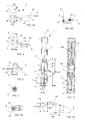
- the packaging and application device 1 shown in FIG. figure 1 comprises a container 2 and an applicator 3 comprising a rod 4 of axis X and rod diameter provided at its end with a brush 5 and connected to the end opposite to a gripping member 7 also constituting a closure member of the container 2.
- the latter comprises a threaded neck 11 on which can be screwed tightly gripping member 7, but could be achieved otherwise.
- p container corresponds to the distance between the top of the neck and the inner surface of the bottom of the container.
- a wiper member 8 can be mounted in the neck 11, as illustrated, and comprises in the example considered a flexible lip 9 intended to wipe the rod 4 and the brush 5 to its withdrawal from the container 2.
- df corresponds to the distance between the lower end of the wiper member and the inner surface of the bottom of the container.
- the container 2 contains a composition P to be applied to the keratinous fibers, in particular the eyelashes or the eyebrows, for example mascara.
- the rod 4 is rectilinear and of circular cross section, but in non-illustrated variants, the rod may be non-rectilinear and / or of non-circular section.
- Fixing the applicator 3 on the container 2 can be done otherwise than by screwing, for example by snapping.
- the brush 5 comprises a twisted core 10 formed for example by a wire folded in U and twisted in one direction to enclose between the turns thus formed bristles made of a natural or synthetic material.
- This wire has for example a diameter of between 0.35 and 1.2 mm, being for example stainless steel, for example of the order of 0.45 mm in diameter.
- d soul is the diameter in which the cross section of the soul fits.
- the core 10 extends along a longitudinal axis Y which may be rectilinear or not and which may or may not coincide with the longitudinal axis X of the rod 4.
- the free ends of the bristles 12 of the brush 5 define an envelope surface E that has been materialized in broken lines on the Figure 2A and schematically represented in perspective at the Figure 2B .
- the envelope surface E is symmetrical with revolution and comprises a first portion 20, cylindrical, of constant cross section and a second portion 22, of variable cross section, for example in the direction of the distal end of the core 21 a first diverging surface 23 and a second converging surface 26 connected by an edge 30 defining a vertex where the radius r , that is to say the distance from the envelope surface E to the Y axis of the soul 10, is the largest for the entire envelope surface E.
- the first surface 23, for example substantially frustoconical, makes it possible, for example, to pass from an envelope surface diameter E which is, for example, approximately 5 mm to a diameter which is, for example, approximately 7.5 mm, over a long distance of the soul which is for example between 7 and 8 mm.
- the second surface 26, for example substantially frustoconical, allows for example to go from a diameter of about 7.5 mm to a diameter of about 4 mm, over a length of about 4 mm.
- the surfaces 23 and 26 are for example substantially symmetrical to one another with respect to a median plane containing the apex 30.
- the length of the portion 22 of variable section, which forms the protuberance of the brush, is for example between 1/3 and 2/3 of that of the portion 20 of constant section.
- the cross section of the brush increases and then decreases as one moves from the proximal end towards the distal end of the envelope surface, along at least two axes X1 and X2 perpendicular to each other, as illustrated in FIG. Figure 2B .
- the radius r increases, reaches the maximum r max , then decreases. It is the same in the longitudinal section plane containing the axis X2.
- the longitudinal sectional planes containing the axes X1 and X2 respectively may be planes of symmetry for the envelope surface.
- the brush 5 is for example manufactured from a cylindrical envelope surface blank of revolution, of diameter corresponding to that of the edge 30, by cutting this blank with a knife having the same profile as the envelope surface in longitudinal section.
- the distance along the Y axis between the proximal end 35 of the envelope surface E and the free end 21 of the core 10 is for example of the order of 27 mm and the distance 1 of the transverse plane containing the ridge 30 to that containing the free end 21 of the core is for example of the order of 5 mm.
- the distance j between the transverse plane containing the crown edge 30 and the proximal end of the envelope surface is for example of the order of 4 mm.
- the angle ⁇ formed between the slopes 40 and 41 of the envelope surface, located respectively on either side of the ridge 30, is greater than 120 °, being for example of the order of 135 ° in the example considered, as can be seen from the figure 18 .
- Each slope 40 or 41 is defined as illustrated in FIG. figure 18 the line that passes through the top of the envelope surface E and which best marries the outline of the envelope surface in a longitudinal section plane, over an interval of 1 mm length along the Y axis, the corresponding side of the vertex.
- the slopes are respectively those of the two portions of cones.
- the angle ⁇ is closer to 180 °.
- the shape factor of the brush in the transverse plane containing the edge of vertex 30, is equal to 1, the envelope surface E having a circular contour centered on the axis Y of the core 21 .
- the form factor is defined by r min / r max , where r max is the largest radius of the considered cross-section, i.e., the largest distance from the Y axis of the web 10 to the envelope surface E and r min denotes the smallest radius, that is to say the smallest distance from the axis Y of the core 10 to the envelope surface E in the plane of section.
- r max is the largest radius of the considered cross-section, i.e., the largest distance from the Y axis of the web 10 to the envelope surface E
- r min denotes the smallest radius, that is to say the smallest distance from the axis Y of the core 10 to the envelope surface E in the plane of section.
- a square cross section, with a centered core will have a form factor of 1 / ⁇ 2.
- the envelope surface E is non-symmetrical of revolution and when the envelope surface has at least at one point along the core a cross section which is not symmetrical of revolution, for example due to the presence of at least one facet 50, as illustrated in FIG. Figure 7A .
- the applicator may also include, as illustrated in Figure 7B at least one ridge 51, which extends for example less than 90 ° around the Y axis.
- This ridge 51 may be formed at the junction of two facets 110 and 111, which may for example be inscribed in a circle C defining the contour of the portion of the envelope surface opposite the peak 51.
- the two facets 110 and 111 may be symmetrical to each other or not, and planar or not.
- the crest 51 may be more or less tapered, depending on the inclination of the facets 110 and 111, and be more or less wide, depending on the spacing between them.
- the portion 29 of the envelope surface E which contains the apex 30 and which is more than 0.9 times distant from the maximum radius r max has, for example, its middle M which substantially coincides with the edge 30, as can be seen on the figure 18 .
- This medium M can be located at a distance from the transverse plane containing the free end 21 of the core 10 which is less than 2.5 times the radius r max , better 1.5 times the radius r max .
- the radius r max is approximately 3.75 mm and the distance 1 between the transverse plane containing the edge 30 and that containing the free end 21 of the core is approximately 5.6 mm.
- the entire envelope surface E has a general shape of ball and at least a portion of the envelope surface, better all thereof, may be substantially spherical to 20%, including the portion between the vertex 30 and the free end 21 of the soul.
- the length of the portion of the core carrying the bristles is for example 12 mm.
- the largest diameter is for example about 10 mm.
- the diameter of the envelope surface at the distal end and the proximal end is for example about 5 mm.
- the brush can be twisted left or right, as shown in the Figures 4 and 5 .
- the core 10 may have a stripped portion 60, not carrying bristles, extending between the portion of the core carrying the bristles and the rod 4.
- This stripped portion 60 may extend over a distance n which may be more or less important, for example between 5 and 10 mm, or even longer when this portion serves as a rod and replaces the conventional plastic rod.
- the shape of the envelope surface E, in the invention, makes it possible to use the applicator for the makeup of the eyelashes, in multiple orientations, as illustrated in FIGS. Figures 6A and 6B .
- bristles located on the core between the transverse plane where the cross section is the largest and the free end of the applicator for example by orienting the latter with the distal end of the applicator. the rod 4 which is directed towards the eyelash fringe.
- bristles of the brush which are located further in recess, the longitudinal axis of the rod being in this case for example oriented substantially parallel to the eyelash fringe, as illustrated in FIG. Figure 6A .
- the applicator When applying the composition to the eyelashes, the applicator may be rotated on itself as if it rolled in contact with the eyelashes approaching their free end, as shown in FIG. Figure 6B .
- the envelope surface E of the brush may have various other forms without departing from the scope of the present invention.
- the envelope surface has a substantially biconical shape.
- the angle ⁇ between the slopes at the top is however relatively large, so as to approach a ball shape.
- the radius r may not decrease to zero at the ends of the envelope surface.
- the diameter of the envelope surface, in this example or in other examples, at the distal end is for example greater than or equal to 4 mm.
- the envelope surface E may, if necessary, be symmetrical on either side of a median plane containing the vertex 30.
- the envelope surface may have a spherical portion which is extended toward the proximal and distal ends by relatively short cylindrical portions 52 and 53.
- the envelope surface E has a shape, in longitudinal section, generally lenticular.
- the cross section defined by the envelope surface E increases for example from a proximal end where the radius r is substantially zero to the vertex 30, then decreases to an end where the radius r can again be substantially zero.
- the vertex 30 may be defined by an edge, as illustrated in the above examples.
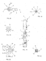
- the vertex 30 may extend over a certain distance along the Y axis, as illustrated on FIG. figure 10 .
- the envelope surface E delimits a maximum cross section of radius r max over a certain distance t before decreasing towards the free end of the core.
- the middle of this portion of radius r max is for example located at a distance l from the free end 21 which is such that the ratio l / r max is less than 1.5.
- the length t is for example greater than or equal to 1 mm.
- the envelope surface E especially in the plane where the cross section is maximum, may have a shape that is not revolution.
- the envelope surface may have in a longitudinal sectional plane, on its portion where the cross section is variable, a contour that is substantially semi-circular on one side of the core and substantially triangular on the other side of the soul, as illustrated in figure 11 .
- the maximum radius r max may be defined for example by the substantially semicircular portion or the substantially triangular portion.
- variable cross section portion is substantially spherical and is connected to a cylindrical cross sectional portion of revolution.
- the applicator may also comprise a distal portion having a substantially spherical envelope surface, as illustrated in FIG. figure 13 , and a proximal portion having a variable cross section, for example forming a succession of grooves or notches 70.
- the angle ⁇ formed between the axis of the core 10 at its proximal end and at its distal end is for example between 1 and 90 °, better between 1 and 60 °, even better 1 and 20, for example 7.
- the core 10 may be deformed after machining the bristles.
- the core 10 can still be curved on its stripped portion 60, as illustrated in FIG. figure 15 .
- the portion of the core carrying the bristles is rectilinear and forms for example an angle ⁇ with the longitudinal axis X of the rod between 1 and 30 °.
- the bent portion can still be located, in a variant not shown, flush with the rod 4.
- the core 10 can be mounted in different ways on the rod 4, being for example introduced into a housing of the rod, for example by force mounting, especially when the core is a twisted metal core.
- the rod 4 may comprise, as illustrated in FIG. figure 16 , a portion 70 of increased flexibility, which can bend when the applicator is brought into contact with the eyelashes and / or when the applicator passes through the wiper member 8 while being withdrawn from the receptacle 2.
- the increased flexibility zone 70 is for example formed by stamping the rod and / or a thinned portion thereof and / or by a portion of a softer material than the rest of the rod.
- the invention is not limited to a packaging and application device comprising only an applicator as described above.
- the device may for example comprise, as illustrated in FIG. figure 17 , a second applicator which is for example integral with the applicator 3 by means of a sleeve 80.
- the second applicator 100 is for example provided with a brush and may be intended for the application of a composition P 'which may have the same formulation as the composition P contained in the container 2 or a different formulation, for example intended to to be applied on the eyelashes before the application of the composition P or after it, or else having a different color or to create a different effect.
- a composition P ' which may have the same formulation as the composition P contained in the container 2 or a different formulation, for example intended to to be applied on the eyelashes before the application of the composition P or after it, or else having a different color or to create a different effect.
- the application elements are bristles added to the core.
- the figure 19 thus represents an alternative embodiment of the packaging and application device, in which the applicator comprises an injected brush 5 at the end of the rod 4.
- the distal end of the applicator may be defined by at least one application element, as illustrated in this figure.
- the application members define an envelope surface E having a cross-section that grows and then decreases from the distal end to the proximal end of the applicator.
- the application elements can be molded in the same material as the soul.
- the application members and the core may be molded into different materials.
- the application elements can be relatively thin and behave similarly to the bristles reported on a twisted core.
- the application members may be relatively rigid and form teeth.
- the applicator elements each extend rectilinearly, some of which are directed towards the distal end of the applicator, the applicator thus having applicator elements connecting to the core in a direction not perpendicular to the applicator.
- longitudinal axis Y of the soul
- the envelope surface E may present over at least a portion of its length, as illustrated in FIG. figure 21 , a cross section of at least partially circular contour.
- the envelope surface may have, over at least a portion of its length, a polygonal cross section, for example more than five sides.
- the envelope surface may, as illustrated, be spherical to within 20%, at least on its portion extending from a plane where the transverse dimension delimited by the envelope surface E is maximum, to the distal end 21.
- the applicator may comprise, as illustrated, application elements oriented towards the proximal end of the applicator.
- the applicator may include application members 12 extending in more than four directions about the axis of the core, better extending in at least eight directions around the Y axis of the core.
- These application elements 12 may be arranged in rows extending along the core and angularly equidistributed around the axis of the core.
- the core 10 is full in the illustrated example but could, in a variant not shown, be hollow.
- the core 10 and the envelope surface E can pass, as illustrated, a maximum cross section at the same axial position on the Y axis.
- the application elements have a variable height so that their free ends define the desired profile for the envelope surface E.
- the core 10 is for example of elongated shape, for example cylindrical, as illustrated.
- the core 10 may be attached to the rod 4 or, in a variant not shown, be molded with the rod.
- the rod 4 comprises for example a housing 37 provided with a relief 38 for snapping a proximal portion 35 of the core 10, provided with a complementary detent relief, for example in the form of a throat as shown in figure 23 .
- the rod 4 is made with a distal portion 40 which is fixed in a housing 41 made at the proximal end of the core 10.
- the radius r of the envelope surface E may for example vary by less than 50% between one quarter and one half of the distance separating the plane containing the apex 30 and the distal end 21 of the applicator.
- the application elements When the applicator is loaded in composition by being introduced into a container through a wiper member, in some embodiments the application elements may bend towards the distal end withdrawal of the applicator.
- the length of the application elements is preferably sufficient so that, during the passage of the applicator through the wiper member of the applicator elements lie down towards the distal end of the applicator.
- the free end of certain application elements may come substantially at the level, along the Y axis, of the distal end of the core, as illustrated in FIG. the figure 26 , for example, exceed this end.
- any of the brushes can be made Figures 8 to 13 with a soul extending along a curved longitudinal axis.
- the hairs can be of any kind and present any section.
- bristles having, in cross section, for example a circular shape with or without flat, flattened, star-shaped, for example in the form of a cross or with several three branches, in the shape of a U, H, T or V , a recessed form, for example circular or square, forming branches, for example flake-shaped, a prismatic shape, for example triangular, square or hexagonal, or an oblong shape, in particular lenticular or hourglass shape.
- Hair with articulated parts may be used in relation to one another. It is also possible to use bristles having at least one capillary groove.
- the bristles may have, before placement on the core, a rectilinear shape or not, for example a wavy shape.
- Hair may be treated to form balls or forks at their ends.
- the bristles may be natural or synthetic and for example be made of a material selected from: PE, PA, in particular PA6, PA6 / 6, PA 6/10 or PA-6/12, HYTREL ®, PEBAX ®, silicone, PU, this list n not being limiting.
- the applicator may comprise a mixture of bristles and the application elements, whether of bristles or teeth, may intersect when the applicator is observed perpendicular to the Y axis, as illustrated in FIG. figure 27 .
- the application elements whether formed of teeth and / or bristles, can thus be magnetizable.
- the application elements can also be made with a material having properties promoting sliding.
- the soul can still be a double soul, formed by two elementary souls twisted together.
- Each elementary soul may comprise two strands twisted together and enclosing hairs.
- the two elementary cores can each be constituted by a branch of a single twisted core folded U-shaped, the two branches being twisted together.
- the application elements can be treated by contact with a hot surface and / or by stamping, so as to break the coil effect or orient them in a circumferential direction around the core.
- Notches can be made in the applicator, especially when it comes to a brush.
- the application elements may be arranged in rows, for example aligned along meridians joining the distal and proximal ends of the core.
- the application elements can be aligned or arranged in staggered rows, as shown in FIG. figure 29 .
- the application elements can extend with a constant spacing along the longitudinal or variable axis, as illustrated in FIG. figure 28 .
Landscapes
- Physics & Mathematics (AREA)
- Geometry (AREA)
- Brushes (AREA)
- Coating Apparatus (AREA)
Claims (15)
- Applikator (5) zum Auftragen eines Produkts auf keratinische Fasern, insbesondere auf Wimpern und/oder Augenbrauen, umfassend:- einen Stift (4),- einen Kern (10), der sich gemäß einer Längsachse (Y) erstreckt,- Auftragungselemente (12), die von dem Kern (10) getragen werden, wobei das distale Ende des Applikators durch den Kern oder mindestens ein Auftragungselement bestimmt ist,- wobei die Auftragungselemente (12) eine Mantelfläche (E) bestimmen,
dadurch gekennzeichnet, dass- der durch die Mantelfläche (E) begrenzte Querschnitt des Applikators in Richtung des distalen Endes (21) des Kerns (10) gemäß mindestens zweier senkrecht zueinander verlaufender Achsen (X1, X2) zunimmt und wieder abnimmt und einen Gipfel (30) mit einem maximalen und für die gesamte Mantelfläche (E) streng größten Radius rmax bestimmt, wobei der Gipfel (30) vom distalen Ende der Mantelfläche um einen entlang der Längsachse gemessenen Abstand (j) entfernt ist, der kleiner oder gleich 1,5 rmax ist,- der, in mindestens einem Längsschnitt beiderseits des Gipfels (30) durch die Steigungen (40, 41) der Mantelfläche (E) gebildete Winkel α über 120° beträgt,wobei der Kern verdreht ist oder die Auftragungselemente mit dem Kern abgeformt sind und sich in mehrere Richtungen um den Kern herum erstrecken und eine variable Höhe aufweisen. - Applikator nach Anspruch 1, wobei die Mantelfläche einen im Wesentlichen kugelförmigen Vorsprung (22) aufweist, der an das distale Ende des Applikators angrenzt, wobei dieser Vorsprung den Gipfel (30) bestimmt.
- Applikator nach Anspruch 1 oder 2, wobei die Mantelfläche, zumindest in der Querebene zum Gipfel (30), einen Formfaktor (rmin /rmax ) über 0,7 aufweist.
- Applikator nach Anspruch 1 oder 3, bei dem der Abstand j ≤ 1,2 rmax ist.
- Applikator nach Anspruch 1, wobei rmax größer oder gleich 2,5 mm.
- Applikator nach Anspruch 1, wobei die Mantelfläche einen bis auf 20% zumindest teilweise kugelförmigen distalen Abschnitt aufweist, insbesondere über eine Strecke von mindestens 2 mm entlang der Längsachse.
- Applikator nach einem der vorhergehenden Ansprüche, wobei die Mantelfläche (E) einen Abschnitt (22) mit einem variablen Querschnitt und einen Abschnitt (20) mit einem konstanten Querschnitt aufweist, wobei der Abschnitt mit einem variablen Querschnitt kürzer als der Abschnitt mit einem konstanten Querschnitt ist.
- Applikator nach einem der vorhergehenden Ansprüche, wobei der Kern einen ersten sichtbaren Abschnitt (60) umfasst, der kein Auftragungselement trägt und sich zwischen einem zweiten Abschnitt des Kerns, der die Auftragungselemente trägt und einem mit dem Kern verbundenen Stift (4) erstreckt, wobei die Länge (11) des ersten Abschnitts (60) grösser oder gleich 5 mm ist.
- Applikator nach einem der vorhergehenden Ansprüche, wobei sich der Gipfel (30) in einem Abstand (rmax ) zwischen 2,5 und 7,5 mm von der Achse (Y) des Kerns (10) befindet.
- Applikator nach einem der vorhergehenden Ansprüche, bei dem das Verhältnis R1 = dmax/dkern grösser oder gleich 2,5 ist, wobei dkern dem Durchmesser entspricht, in den der Querschnitt des Kerns eingeschrieben ist.
- Applikator nach einem der vorhergehenden Ansprüche, bei dem das Verhältnis R2 = dmax/dstift grösser oder gleich 2,5 ist, wobei dstift dem maximalen Durchmesser des Stifts entspricht.
- Applikator nach einem der vorhergehenden Ansprüche, bei dem die Auftragungselemente aus demselben Werkstoff wie der Kern geformt sind.
- Applikator nach einem der Ansprüche 1 bis 11, bei dem die Auftragungselemente und der Kern aus verschiedenen Werkstoffen geformt sind.
- Konditionierungs- und Auftragungsvorrichtung zum Auftragen einer Zusammensetzung auf keratinische Fasern, umfassend:- einen Behälter, der die auf die keratinischen Fasern aufzutragende Zusammensetzung enthält,- ein Abstreiforgan,- einen Applikator nach einem der vorhergehenden Ansprüche.
- Vorrichtung nach dem vorhergehenden Anspruch, bei der das Verhältnis R3 = dmax/pbehälter grösser oder gleich 3 ist, wobei pbehälter dem Abstand zwischen einem Gipfel des Behälters in Abwesenheit des Applikators und der inneren Oberfläche des Bodens des Behälters entspricht.
Applications Claiming Priority (1)
| Application Number | Priority Date | Filing Date | Title |
|---|---|---|---|
| FR0754215A FR2914163B1 (fr) | 2007-04-02 | 2007-04-02 | Applicateur pour appliquer une composition sur les cils |
Publications (2)
| Publication Number | Publication Date |
|---|---|
| EP1977662A1 EP1977662A1 (de) | 2008-10-08 |
| EP1977662B1 true EP1977662B1 (de) | 2015-05-20 |
Family
ID=38738844
Family Applications (1)
| Application Number | Title | Priority Date | Filing Date |
|---|---|---|---|
| EP20080153974 Not-in-force EP1977662B1 (de) | 2007-04-02 | 2008-04-02 | Applikator zum Auftragen einer Zusammensetzung auf die Wimpern |
Country Status (4)
| Country | Link |
|---|---|
| US (1) | US8851087B2 (de) |
| EP (1) | EP1977662B1 (de) |
| ES (1) | ES2544651T3 (de) |
| FR (1) | FR2914163B1 (de) |
Families Citing this family (18)
| Publication number | Priority date | Publication date | Assignee | Title |
|---|---|---|---|---|
| FR2914162B1 (fr) * | 2007-04-02 | 2010-10-29 | Oreal | Applicateur pour appliquer une composition sur les cils |
| FR2914163B1 (fr) | 2007-04-02 | 2009-06-05 | Oreal | Applicateur pour appliquer une composition sur les cils |
| FR2922422B1 (fr) | 2007-10-23 | 2009-12-18 | Oreal | Applicateur pour peigner ou appliquer un produit sur les cils |
| FR2922421B1 (fr) | 2007-10-23 | 2010-01-29 | Oreal | Applicateur pour peigner ou appliquer un produit sur les cils ou les sourcils |
| FR2983689A1 (fr) * | 2007-10-23 | 2013-06-14 | Oreal | Applicateur pour peigner ou appliquer un produit sur les cils et/ou les sourcils |
| FR2922420B1 (fr) * | 2007-10-23 | 2011-04-01 | Oreal | Applicateur pour l'application d'un produit sur les cils ou les sourcils |
| US10086411B1 (en) * | 2008-04-06 | 2018-10-02 | Matthew Justin Michel | Whisk wiper |
| FR2929495B1 (fr) * | 2008-04-08 | 2011-12-09 | Oreal | Ensemble de conditionnement et d'application d'un produit |
| FR2932656B1 (fr) * | 2008-06-18 | 2012-11-16 | Oreal | Dispositif de conditionnement et d'application, notamment de mascara |
| US8136536B2 (en) * | 2008-09-24 | 2012-03-20 | Elc Management Llc | Shape memory polymer mascara brush |
| FR2943225B1 (fr) | 2009-03-17 | 2011-06-03 | Oreal | Dispositif de conditionnement et d'application d'au moins une composition cosmetique solide |
| FR2946847B1 (fr) | 2009-06-23 | 2011-08-19 | Oreal | Applicateur a ame torsadee chauffante |
| USD616608S1 (en) | 2009-10-26 | 2010-05-25 | Mary Kay Inc. | Mascara container |
| FR2963217B1 (fr) | 2010-07-28 | 2012-09-21 | Oreal | Dispositif de conditionnement et d'application d'au moins une composition cosmetique solide |
| CN106039548A (zh) * | 2016-06-29 | 2016-10-26 | 黄骅市康田医疗器械有限公司 | 一体成型涂药棒及其制备工艺 |
| FR3072255B1 (fr) * | 2017-10-12 | 2021-07-16 | Oreal | Applicateur pour l'application d'un produit sur les matieres keratiniques |
| US11337506B1 (en) * | 2021-08-05 | 2022-05-24 | Ben Thai Pham | Nail polish bottle |
| USD1068168S1 (en) * | 2024-07-25 | 2025-03-25 | Lin Xiu | Eyelash conditioner container |
Family Cites Families (49)
| Publication number | Priority date | Publication date | Assignee | Title |
|---|---|---|---|---|
| US508603A (en) | 1893-11-14 | Combined table and writing-cabinet | ||
| US2135112A (en) | 1938-03-24 | 1938-11-01 | Price Rufus Hamond | Windmill pump attachment |
| US2245906A (en) | 1939-07-21 | 1941-06-17 | Thorpe W Deakers | Cosmetic device |
| US3214782A (en) * | 1964-01-16 | 1965-11-02 | Helen Rubinstein Inc | Mascara applicator |
| US4030199A (en) * | 1975-05-12 | 1977-06-21 | E-Z Floss | Handle for disposable appliance |
| FR2506581A1 (fr) * | 1981-05-27 | 1982-12-03 | Oreal | Brosse de maquillage perfectionnee et, notament brosse a cils |
| US4586520A (en) | 1983-11-02 | 1986-05-06 | Plough, Inc. | Mascara applicator |
| CH681137A5 (de) * | 1986-08-14 | 1993-01-29 | Saxer Ulrich P | |
| FR2625083B1 (fr) * | 1987-12-29 | 1990-06-01 | Oreal | Ensemble de maquillage a utilisation unique |
| US4982838A (en) | 1989-05-31 | 1991-01-08 | Georg Karl Geka-Brush Gmbh | Disposable mascara tester |
| DE69225924T2 (de) | 1991-04-29 | 1998-11-19 | Henlopen Mfg Co Inc | Mascara-Bürste mit nichtkontinuierlichem Profil |
| US5226744A (en) | 1991-11-12 | 1993-07-13 | Risdon Corporation | Cosmetic product self agitation container |
| US5379253A (en) * | 1992-06-01 | 1995-01-03 | National Semiconductor Corporation | High density EEPROM cell array with novel programming scheme and method of manufacture |
| FR2715038B1 (fr) | 1994-01-14 | 1996-03-15 | Oreal | Brosse pour appliquer un produit cosmétique, notamment du mascara. |
| US5418999A (en) | 1994-03-22 | 1995-05-30 | Preston-Smith Technologies, Inc. | Mouse cleaner |
| FR2730910B1 (fr) | 1995-02-23 | 1997-04-11 | Oreal | Applicateur de produit cosmetique |
| US5595198A (en) * | 1995-06-07 | 1997-01-21 | Risdon Corporation | Mascara applicator and method of making the same |
| FR2736248B1 (fr) * | 1995-07-05 | 1997-08-01 | Oreal | Ensemble d'application de produit de consistance pateuse tel que du rouge a levres |
| FR2745481B1 (fr) | 1996-02-29 | 1998-04-30 | Oreal | Brosse progressive pour appliquer un produit cosmetique, notamment du mascara |
| FR2748913B1 (fr) | 1996-05-24 | 1998-08-07 | Oreal | Brosse a crans et dispositif de maquillage comprenant cette brosse |
| US5989229A (en) * | 1997-05-28 | 1999-11-23 | Becton, Dickinson And Company | Needle cover assembly having self-contained drug applicator |
| US6634051B1 (en) * | 1997-09-22 | 2003-10-21 | Centrix, Inc. | Disposable dental applicator |
| US6158912A (en) | 1999-05-24 | 2000-12-12 | Color Access, Inc. | Flexible wall cosmetic container |
| US6082999A (en) * | 1999-07-27 | 2000-07-04 | Tcherny; Iosif | Interdental device and container |
| DE10029378B4 (de) | 2000-06-20 | 2005-06-16 | Geka Brush Gmbh | Applikationseinrichtung für Kosmetikflüssigkeiten, insbesondere Mascara-Test-Applikator |
| JP2002172019A (ja) * | 2000-12-06 | 2002-06-18 | Shinohara:Kk | 化粧用ブラシ |
| FR2821536B1 (fr) * | 2001-03-01 | 2003-05-16 | Oreal | Brosse pour l'application d'un produit sur les fibres keratiniques |
| FR2822656B1 (fr) | 2001-04-03 | 2003-05-30 | Oreal | Ensemble de conditionnement et d'application, notamment pour un produit cosmetique |
| US6572296B2 (en) | 2001-05-31 | 2003-06-03 | Henlopen Manufacturing Co., Inc. | Containers simulating collapsible tubes, packages including such containers, and methods of making them |
| FR2825246B1 (fr) | 2001-06-05 | 2004-06-04 | Oreal | Dispositif de conditionnement et/ou d'application comprenant des fibres comportant des particules capables d'absorber un liquide ou un compose en solution dans ce liquide ou de se dissoudre dans un liquide |
| US7261483B2 (en) * | 2002-04-30 | 2007-08-28 | L'ORéAL S.A. | Device, system, and method for applying a product |
| FR2840166B1 (fr) | 2002-06-03 | 2005-01-28 | Techpack Int | Applicateur a bout rotatif et distributeur comprenant ledit applicateur |
| DE10233341B4 (de) * | 2002-07-23 | 2015-02-12 | Geka Gmbh | Sichelförmiger Applikator für flüssige oder pastöse Medien |
| DE20213851U1 (de) * | 2002-09-03 | 2002-11-14 | Blume, Niels, 20251 Hamburg | Spezial-Applikationsbürste mit Zeichenfunktion an der Spitze einer Mascara |
| US8210186B2 (en) | 2002-11-27 | 2012-07-03 | L'oreal | Applicator for applying a substance onto keratinous fibers |
| FR2852500B1 (fr) * | 2003-03-20 | 2007-02-23 | Oreal | Brosse et dispositif de conditionnement et d'application comportant une telle brosse |
| FR2868669B1 (fr) | 2004-04-09 | 2007-07-20 | Oreal | Dispositif de conditionnement et d'application d'un produit. |
| FR2876890B1 (fr) | 2004-10-21 | 2007-06-22 | Oreal | Dispositif de conditionnement et d'application d'un produit sur le cils ou les sourcils, notamment du mascara. |
| FR2881931B1 (fr) | 2005-02-11 | 2007-04-27 | Oreal | Dispositif de conditionnement et d'application |
| FR2884397B1 (fr) | 2005-04-19 | 2007-07-06 | Parfums Givenchy Sa | Applicateur a mascara perfectionne |
| WO2007042061A1 (de) * | 2005-10-12 | 2007-04-19 | Schwan-Stabilo Cosmetics Gmbh & Co. Kg | Dip-applikator |
| GB2432513A (en) | 2005-11-25 | 2007-05-30 | Melinda Sue Lane | Applicator |
| US8245716B2 (en) | 2006-09-11 | 2012-08-21 | Albea Services | Flocked cosmetic applicators, methods of manufacture and dispensers including such applicators |
| FR2906115B1 (fr) | 2006-09-26 | 2011-04-01 | Alcan Packaging Beauty Serv | Embout applicateur typiquement spherique pour application de produits cosmetiques |
| FR2914163B1 (fr) | 2007-04-02 | 2009-06-05 | Oreal | Applicateur pour appliquer une composition sur les cils |
| FR2914162B1 (fr) | 2007-04-02 | 2010-10-29 | Oreal | Applicateur pour appliquer une composition sur les cils |
| BRPI0811533A2 (pt) * | 2007-05-04 | 2014-10-14 | Baxter Int | Método para a produção de um vírus |
| FR2929495B1 (fr) | 2008-04-08 | 2011-12-09 | Oreal | Ensemble de conditionnement et d'application d'un produit |
| US20100189491A1 (en) | 2009-01-27 | 2010-07-29 | L'ORéAL S.A. | Packaging and applicator device |
-
2007
- 2007-04-02 FR FR0754215A patent/FR2914163B1/fr not_active Expired - Fee Related
-
2008
- 2008-04-02 EP EP20080153974 patent/EP1977662B1/de not_active Not-in-force
- 2008-04-02 ES ES08153974.4T patent/ES2544651T3/es active Active
- 2008-04-02 US US12/078,581 patent/US8851087B2/en not_active Expired - Fee Related
Also Published As
| Publication number | Publication date |
|---|---|
| US20080283077A1 (en) | 2008-11-20 |
| US8851087B2 (en) | 2014-10-07 |
| FR2914163B1 (fr) | 2009-06-05 |
| FR2914163A1 (fr) | 2008-10-03 |
| EP1977662A1 (de) | 2008-10-08 |
| ES2544651T3 (es) | 2015-09-02 |
Similar Documents
| Publication | Publication Date | Title |
|---|---|---|
| EP1977661B1 (de) | Applikator zum Auftragen einer Zusammensetzung auf die Wimpern | |
| EP1977662A1 (de) | Applikator zum Auftragen einer Zusammensetzung auf die Wimpern | |
| EP1649777B1 (de) | Behälter und Applikator zum Auftragen eines Produktes auf die Wimpern oder Augenbrauen, insbesondere Maskara | |
| EP0978241B1 (de) | Vorrichtung zum Auftragen von Schminkprodukten mit einer Bürste, Verfahren zu dessen Herstellung und Auftragseinheit mit einer solchen Vorrichtung | |
| EP2229840B1 (de) | Applikator zum Auftragen eines Kosmetik-, Schmink- oder Pflegeproduktes, und Verfahren zu seiner Herstellung | |
| EP1177745B1 (de) | Vorrichtung zum Auftragen eines Produktes, insbesondere eines Schmink- oder Pflegeproduktes auf keratinische Fasern, insbesondere auf Wimpern oder Augenbrauen | |
| EP1917883B1 (de) | Applikator zum Auftragen eines Produkts auf Wimpern oder Augenbrauen | |
| EP2149314B1 (de) | Wimperntusche-Bürstchen, das Borsten mit verschiedenen Durchmessern besitzt | |
| EP1938709B1 (de) | Mascarabürste | |
| CA2314435C (fr) | Applicateur de produit liquide, pateux ou pulverulent comportant des fibres torsadees, et ensemble d'application ainsi equipe | |
| EP2005857B1 (de) | Applikator zum Auftragen eines Produkts auf Wimpern und/oder Augenbrauen | |
| FR2961384B1 (fr) | Applicateur d'un produit cosmetique, de maquillage ou de soin, sur les cils ou les sourcils | |
| EP1767119A1 (de) | Applikator zum Auftragen eines Produktes auf die Wimpern | |
| EP2332441A1 (de) | Vorrichtung zum Kämmen und/oder Bürsten der Wimpern und/oder der Augenbrauen und/oder zum Anwenden eines Produktes darauf | |
| EP1175847A1 (de) | Vorrichtung zum Auftragen eines Produktes auf keratinische Fasern | |
| FR2932657A1 (fr) | Brosse a mascara. | |
| FR2934478A1 (fr) | Applicateur pour peigner et/ou appliquer un produit sur les cils et/ou les sourcils | |
| FR2891708A1 (fr) | Dispositif de conditionnement et d'application d'un produit. | |
| EP1454561B1 (de) | Auftragevorrichtung und Aufbewahrungs- und Ausgabevorrichtung mit einer solchen Auftragevorrichtung | |
| FR3072008A1 (fr) | Applicateur pour appliquer un produit cosmetique | |
| FR3045295A1 (fr) | Applicateur d'un produit cosmetique, de maquillage ou de soin, sur les cils et/ou les sourcils | |
| FR3111774A1 (fr) | Applicateur hybride à brosse torsadée | |
| FR3074661A1 (fr) | Applicateur pour appliquer un produit cosmetique | |
| FR3070243A1 (fr) | Applicateur pour l'application d'un produit sur les cils et/ou les sourcils. | |
| FR3156018A1 (fr) | Applicateur pour appliquer une composition cosmétique sur les cils ou sourcils |
Legal Events
| Date | Code | Title | Description |
|---|---|---|---|
| PUAI | Public reference made under article 153(3) epc to a published international application that has entered the european phase |
Free format text: ORIGINAL CODE: 0009012 |
|
| 17P | Request for examination filed |
Effective date: 20080402 |
|
| AK | Designated contracting states |
Kind code of ref document: A1 Designated state(s): AT BE BG CH CY CZ DE DK EE ES FI FR GB GR HR HU IE IS IT LI LT LU LV MC MT NL NO PL PT RO SE SI SK TR |
|
| AX | Request for extension of the european patent |
Extension state: AL BA MK RS |
|
| 17Q | First examination report despatched |
Effective date: 20081117 |
|
| AKX | Designation fees paid |
Designated state(s): AT BE BG CH CY CZ DE DK EE ES FI FR GB GR HR HU IE IS IT LI LT LU LV MC MT NL NO PL PT RO SE SI SK TR |
|
| GRAP | Despatch of communication of intention to grant a patent |
Free format text: ORIGINAL CODE: EPIDOSNIGR1 |
|
| INTG | Intention to grant announced |
Effective date: 20141119 |
|
| INTG | Intention to grant announced |
Effective date: 20141126 |
|
| GRAS | Grant fee paid |
Free format text: ORIGINAL CODE: EPIDOSNIGR3 |
|
| GRAA | (expected) grant |
Free format text: ORIGINAL CODE: 0009210 |
|
| AK | Designated contracting states |
Kind code of ref document: B1 Designated state(s): AT BE BG CH CY CZ DE DK EE ES FI FR GB GR HR HU IE IS IT LI LT LU LV MC MT NL NO PL PT RO SE SI SK TR |
|
| REG | Reference to a national code |
Ref country code: GB Ref legal event code: FG4D Free format text: NOT ENGLISH |
|
| REG | Reference to a national code |
Ref country code: CH Ref legal event code: EP |
|
| REG | Reference to a national code |
Ref country code: AT Ref legal event code: REF Ref document number: 727270 Country of ref document: AT Kind code of ref document: T Effective date: 20150615 |
|
| REG | Reference to a national code |
Ref country code: IE Ref legal event code: FG4D Free format text: LANGUAGE OF EP DOCUMENT: FRENCH |
|
| REG | Reference to a national code |
Ref country code: DE Ref legal event code: R096 Ref document number: 602008038194 Country of ref document: DE |
|
| REG | Reference to a national code |
Ref country code: ES Ref legal event code: FG2A Ref document number: 2544651 Country of ref document: ES Kind code of ref document: T3 Effective date: 20150902 |
|
| REG | Reference to a national code |
Ref country code: AT Ref legal event code: MK05 Ref document number: 727270 Country of ref document: AT Kind code of ref document: T Effective date: 20150520 |
|
| REG | Reference to a national code |
Ref country code: LT Ref legal event code: MG4D |
|
| REG | Reference to a national code |
Ref country code: NL Ref legal event code: MP Effective date: 20150520 |
|
| PG25 | Lapsed in a contracting state [announced via postgrant information from national office to epo] |
Ref country code: HR Free format text: LAPSE BECAUSE OF FAILURE TO SUBMIT A TRANSLATION OF THE DESCRIPTION OR TO PAY THE FEE WITHIN THE PRESCRIBED TIME-LIMIT Effective date: 20150520 Ref country code: PT Free format text: LAPSE BECAUSE OF FAILURE TO SUBMIT A TRANSLATION OF THE DESCRIPTION OR TO PAY THE FEE WITHIN THE PRESCRIBED TIME-LIMIT Effective date: 20150921 Ref country code: NO Free format text: LAPSE BECAUSE OF FAILURE TO SUBMIT A TRANSLATION OF THE DESCRIPTION OR TO PAY THE FEE WITHIN THE PRESCRIBED TIME-LIMIT Effective date: 20150820 Ref country code: FI Free format text: LAPSE BECAUSE OF FAILURE TO SUBMIT A TRANSLATION OF THE DESCRIPTION OR TO PAY THE FEE WITHIN THE PRESCRIBED TIME-LIMIT Effective date: 20150520 Ref country code: LT Free format text: LAPSE BECAUSE OF FAILURE TO SUBMIT A TRANSLATION OF THE DESCRIPTION OR TO PAY THE FEE WITHIN THE PRESCRIBED TIME-LIMIT Effective date: 20150520 |
|
| PG25 | Lapsed in a contracting state [announced via postgrant information from national office to epo] |
Ref country code: LV Free format text: LAPSE BECAUSE OF FAILURE TO SUBMIT A TRANSLATION OF THE DESCRIPTION OR TO PAY THE FEE WITHIN THE PRESCRIBED TIME-LIMIT Effective date: 20150520 Ref country code: BG Free format text: LAPSE BECAUSE OF FAILURE TO SUBMIT A TRANSLATION OF THE DESCRIPTION OR TO PAY THE FEE WITHIN THE PRESCRIBED TIME-LIMIT Effective date: 20150820 Ref country code: GR Free format text: LAPSE BECAUSE OF FAILURE TO SUBMIT A TRANSLATION OF THE DESCRIPTION OR TO PAY THE FEE WITHIN THE PRESCRIBED TIME-LIMIT Effective date: 20150821 Ref country code: AT Free format text: LAPSE BECAUSE OF FAILURE TO SUBMIT A TRANSLATION OF THE DESCRIPTION OR TO PAY THE FEE WITHIN THE PRESCRIBED TIME-LIMIT Effective date: 20150520 Ref country code: IS Free format text: LAPSE BECAUSE OF FAILURE TO SUBMIT A TRANSLATION OF THE DESCRIPTION OR TO PAY THE FEE WITHIN THE PRESCRIBED TIME-LIMIT Effective date: 20150920 |
|
| PG25 | Lapsed in a contracting state [announced via postgrant information from national office to epo] |
Ref country code: DK Free format text: LAPSE BECAUSE OF FAILURE TO SUBMIT A TRANSLATION OF THE DESCRIPTION OR TO PAY THE FEE WITHIN THE PRESCRIBED TIME-LIMIT Effective date: 20150520 Ref country code: EE Free format text: LAPSE BECAUSE OF FAILURE TO SUBMIT A TRANSLATION OF THE DESCRIPTION OR TO PAY THE FEE WITHIN THE PRESCRIBED TIME-LIMIT Effective date: 20150520 |
|
| REG | Reference to a national code |
Ref country code: DE Ref legal event code: R097 Ref document number: 602008038194 Country of ref document: DE |
|
| PG25 | Lapsed in a contracting state [announced via postgrant information from national office to epo] |
Ref country code: RO Free format text: LAPSE BECAUSE OF NON-PAYMENT OF DUE FEES Effective date: 20150520 Ref country code: CZ Free format text: LAPSE BECAUSE OF FAILURE TO SUBMIT A TRANSLATION OF THE DESCRIPTION OR TO PAY THE FEE WITHIN THE PRESCRIBED TIME-LIMIT Effective date: 20150520 Ref country code: PL Free format text: LAPSE BECAUSE OF FAILURE TO SUBMIT A TRANSLATION OF THE DESCRIPTION OR TO PAY THE FEE WITHIN THE PRESCRIBED TIME-LIMIT Effective date: 20150520 Ref country code: SK Free format text: LAPSE BECAUSE OF FAILURE TO SUBMIT A TRANSLATION OF THE DESCRIPTION OR TO PAY THE FEE WITHIN THE PRESCRIBED TIME-LIMIT Effective date: 20150520 |
|
| REG | Reference to a national code |
Ref country code: FR Ref legal event code: PLFP Year of fee payment: 9 |
|
| PLBE | No opposition filed within time limit |
Free format text: ORIGINAL CODE: 0009261 |
|
| STAA | Information on the status of an ep patent application or granted ep patent |
Free format text: STATUS: NO OPPOSITION FILED WITHIN TIME LIMIT |
|
| 26N | No opposition filed |
Effective date: 20160223 |
|
| PG25 | Lapsed in a contracting state [announced via postgrant information from national office to epo] |
Ref country code: SI Free format text: LAPSE BECAUSE OF FAILURE TO SUBMIT A TRANSLATION OF THE DESCRIPTION OR TO PAY THE FEE WITHIN THE PRESCRIBED TIME-LIMIT Effective date: 20150520 |
|
| PG25 | Lapsed in a contracting state [announced via postgrant information from national office to epo] |
Ref country code: BE Free format text: LAPSE BECAUSE OF NON-PAYMENT OF DUE FEES Effective date: 20160430 |
|
| REG | Reference to a national code |
Ref country code: CH Ref legal event code: PL |
|
| PG25 | Lapsed in a contracting state [announced via postgrant information from national office to epo] |
Ref country code: LU Free format text: LAPSE BECAUSE OF FAILURE TO SUBMIT A TRANSLATION OF THE DESCRIPTION OR TO PAY THE FEE WITHIN THE PRESCRIBED TIME-LIMIT Effective date: 20160402 |
|
| REG | Reference to a national code |
Ref country code: IE Ref legal event code: MM4A |
|
| PG25 | Lapsed in a contracting state [announced via postgrant information from national office to epo] |
Ref country code: LI Free format text: LAPSE BECAUSE OF NON-PAYMENT OF DUE FEES Effective date: 20160430 Ref country code: CH Free format text: LAPSE BECAUSE OF NON-PAYMENT OF DUE FEES Effective date: 20160430 |
|
| REG | Reference to a national code |
Ref country code: FR Ref legal event code: PLFP Year of fee payment: 10 |
|
| PG25 | Lapsed in a contracting state [announced via postgrant information from national office to epo] |
Ref country code: IE Free format text: LAPSE BECAUSE OF NON-PAYMENT OF DUE FEES Effective date: 20160402 |
|
| PG25 | Lapsed in a contracting state [announced via postgrant information from national office to epo] |
Ref country code: NL Free format text: LAPSE BECAUSE OF FAILURE TO SUBMIT A TRANSLATION OF THE DESCRIPTION OR TO PAY THE FEE WITHIN THE PRESCRIBED TIME-LIMIT Effective date: 20150520 Ref country code: SE Free format text: LAPSE BECAUSE OF FAILURE TO SUBMIT A TRANSLATION OF THE DESCRIPTION OR TO PAY THE FEE WITHIN THE PRESCRIBED TIME-LIMIT Effective date: 20150520 |
|
| REG | Reference to a national code |
Ref country code: FR Ref legal event code: PLFP Year of fee payment: 11 |
|
| PG25 | Lapsed in a contracting state [announced via postgrant information from national office to epo] |
Ref country code: HU Free format text: LAPSE BECAUSE OF FAILURE TO SUBMIT A TRANSLATION OF THE DESCRIPTION OR TO PAY THE FEE WITHIN THE PRESCRIBED TIME-LIMIT; INVALID AB INITIO Effective date: 20080402 Ref country code: CY Free format text: LAPSE BECAUSE OF FAILURE TO SUBMIT A TRANSLATION OF THE DESCRIPTION OR TO PAY THE FEE WITHIN THE PRESCRIBED TIME-LIMIT Effective date: 20150520 |
|
| PG25 | Lapsed in a contracting state [announced via postgrant information from national office to epo] |
Ref country code: MT Free format text: LAPSE BECAUSE OF FAILURE TO SUBMIT A TRANSLATION OF THE DESCRIPTION OR TO PAY THE FEE WITHIN THE PRESCRIBED TIME-LIMIT Effective date: 20150520 Ref country code: MC Free format text: LAPSE BECAUSE OF FAILURE TO SUBMIT A TRANSLATION OF THE DESCRIPTION OR TO PAY THE FEE WITHIN THE PRESCRIBED TIME-LIMIT Effective date: 20150520 Ref country code: TR Free format text: LAPSE BECAUSE OF FAILURE TO SUBMIT A TRANSLATION OF THE DESCRIPTION OR TO PAY THE FEE WITHIN THE PRESCRIBED TIME-LIMIT Effective date: 20150520 |
|
| PGFP | Annual fee paid to national office [announced via postgrant information from national office to epo] |
Ref country code: ES Payment date: 20190503 Year of fee payment: 12 |
|
| PGFP | Annual fee paid to national office [announced via postgrant information from national office to epo] |
Ref country code: GB Payment date: 20200325 Year of fee payment: 13 |
|
| PGFP | Annual fee paid to national office [announced via postgrant information from national office to epo] |
Ref country code: FR Payment date: 20200312 Year of fee payment: 13 |
|
| PGFP | Annual fee paid to national office [announced via postgrant information from national office to epo] |
Ref country code: DE Payment date: 20200317 Year of fee payment: 13 |
|
| PGFP | Annual fee paid to national office [announced via postgrant information from national office to epo] |
Ref country code: IT Payment date: 20200312 Year of fee payment: 13 |
|
| REG | Reference to a national code |
Ref country code: ES Ref legal event code: FD2A Effective date: 20210826 |
|
| REG | Reference to a national code |
Ref country code: DE Ref legal event code: R119 Ref document number: 602008038194 Country of ref document: DE |
|
| GBPC | Gb: european patent ceased through non-payment of renewal fee |
Effective date: 20210402 |
|
| PG25 | Lapsed in a contracting state [announced via postgrant information from national office to epo] |
Ref country code: GB Free format text: LAPSE BECAUSE OF NON-PAYMENT OF DUE FEES Effective date: 20210402 Ref country code: FR Free format text: LAPSE BECAUSE OF NON-PAYMENT OF DUE FEES Effective date: 20210430 Ref country code: DE Free format text: LAPSE BECAUSE OF NON-PAYMENT OF DUE FEES Effective date: 20211103 |
|
| PG25 | Lapsed in a contracting state [announced via postgrant information from national office to epo] |
Ref country code: ES Free format text: LAPSE BECAUSE OF NON-PAYMENT OF DUE FEES Effective date: 20200403 |
|
| PG25 | Lapsed in a contracting state [announced via postgrant information from national office to epo] |
Ref country code: IT Free format text: LAPSE BECAUSE OF NON-PAYMENT OF DUE FEES Effective date: 20200402 |
|
| PG25 | Lapsed in a contracting state [announced via postgrant information from national office to epo] |
Ref country code: IT Free format text: LAPSE BECAUSE OF NON-PAYMENT OF DUE FEES Effective date: 20210402 |