EP1977677A1 - Instrument endoscopique - Google Patents
Instrument endoscopique Download PDFInfo
- Publication number
- EP1977677A1 EP1977677A1 EP07007041A EP07007041A EP1977677A1 EP 1977677 A1 EP1977677 A1 EP 1977677A1 EP 07007041 A EP07007041 A EP 07007041A EP 07007041 A EP07007041 A EP 07007041A EP 1977677 A1 EP1977677 A1 EP 1977677A1
- Authority
- EP
- European Patent Office
- Prior art keywords
- tubular shaft
- pipe sections
- endoscopic instrument
- instrument according
- connecting webs
- Prior art date
- Legal status (The legal status is an assumption and is not a legal conclusion. Google has not performed a legal analysis and makes no representation as to the accuracy of the status listed.)
- Granted
Links
- 230000002093 peripheral effect Effects 0.000 claims description 30
- 230000006835 compression Effects 0.000 claims description 9
- 238000007906 compression Methods 0.000 claims description 9
- 230000009975 flexible effect Effects 0.000 description 10
- 238000005452 bending Methods 0.000 description 7
- 230000005540 biological transmission Effects 0.000 description 4
- 230000000694 effects Effects 0.000 description 2
- 238000010894 electron beam technology Methods 0.000 description 2
- 230000015572 biosynthetic process Effects 0.000 description 1
- 230000007423 decrease Effects 0.000 description 1
- 238000006073 displacement reaction Methods 0.000 description 1
- 230000005489 elastic deformation Effects 0.000 description 1
- 230000009916 joint effect Effects 0.000 description 1
- 238000004091 panning Methods 0.000 description 1
- 238000007493 shaping process Methods 0.000 description 1
Images




Classifications
-
- A—HUMAN NECESSITIES
- A61—MEDICAL OR VETERINARY SCIENCE; HYGIENE
- A61B—DIAGNOSIS; SURGERY; IDENTIFICATION
- A61B1/00—Instruments for performing medical examinations of the interior of cavities or tubes of the body by visual or photographical inspection, e.g. endoscopes; Illuminating arrangements therefor
- A61B1/005—Flexible endoscopes
- A61B1/0051—Flexible endoscopes with controlled bending of insertion part
- A61B1/0055—Constructional details of insertion parts, e.g. vertebral elements
- A61B1/0056—Constructional details of insertion parts, e.g. vertebral elements the insertion parts being asymmetric, e.g. for unilateral bending mechanisms
-
- A—HUMAN NECESSITIES
- A61—MEDICAL OR VETERINARY SCIENCE; HYGIENE
- A61B—DIAGNOSIS; SURGERY; IDENTIFICATION
- A61B1/00—Instruments for performing medical examinations of the interior of cavities or tubes of the body by visual or photographical inspection, e.g. endoscopes; Illuminating arrangements therefor
- A61B1/00064—Constructional details of the endoscope body
- A61B1/00071—Insertion part of the endoscope body
Definitions
- the invention relates to an endoscopic instrument with a flexibly formed tubular shaft.
- an endoscopic instrument which has a bendable or flexible tubular shaft.
- This tubular shaft consists of several pipe sections which are hinged together.
- a disadvantage of this instrument is that the individual pipe sections must be biased to transfer essential forces can.
- a groove is provided in this known instrument in the wall of the tubular shaft, in which a traction element engages positively.
- the endoscopic instrument according to the invention has a flexibly formed tubular shaft which is formed from a plurality of tube sections.
- the pipe sections are arranged axially one behind the other and each articulated to each other, so that the individual pipe sections can pivot against each other articulated.
- the individual pipe sections are connected to each other via at least one resilient connecting web.
- the connecting web or the connecting webs respectively connect adjacent pipe sections in such a way that the connecting web is resilient in the axial direction of the tubular shaft.
- the connecting webs are connected to the adjacent pipe sections preferably physically, in particular cohesively.
- the arrangement of the additional connecting web has the advantage that compared to the purely articulated connection a firmer connection of the individual pipe sections is created, which allows a greater power transmission. At the same time ensures the resilient design of the connecting web sufficient mobility between the individual pipe sections, so that a great flexibility of the tubular shaft is maintained.
- the connecting webs ensure that in addition to the articulated connection a firm connection between the individual pipe sections, so that they are held together.
- the connecting web can particularly preferably transmit forces acting transversely to the axial direction, which can not be transmitted by the articulated connections.
- the connecting webs are formed integrally with the adjacent pipe sections. This allows a firm connection of all pipe sections, without complicated assembly operations would be required.
- the connection of the connecting web to the pipe sections can be made extremely slim or thin, so that the free lumen can be formed as large as possible inside the tubular shaft.
- the connecting webs are further preferred part of the peripheral walls of the pipe sections. Ie. the connecting webs are formed in the peripheral walls of the pipe sections or the tubular shaft itself.
- This embodiment has the advantage that neither the outer diameter of the tubular shaft is increased, nor the free lumen is reduced in the interior of the tubular shaft through the connecting webs.
- the connecting webs are due to the formation in the peripheral wall in the axial direction aligned in the peripheral wall and cantilever in the radial direction preferably neither inwardly nor outwardly from the peripheral wall.
- the at least one connecting web in the axial direction of the tubular shaft acts as a tension spring.
- a connecting web is preferably arranged on the side of the tubular shaft, which is extended or expanded when the tubular shaft is bent. This then causes the connecting web is stretched when bending the tubular shaft, so that due to the action as a tension spring restoring forces are generated, which automatically withdraw the tubular shaft in its extended position or supported the movement back into the extended position.
- the connecting web is arranged on the peripheral side, to which the deflection of the tubular shaft takes place, d. H. on the peripheral side, which is compressed.
- the deflection of the tubular shaft can be effected in a known manner by a traction means which extends on a peripheral side of the tubular shaft in the axial direction.
- this traction means is inserted in a groove in the peripheral wall.
- the connecting webs between the several pipe sections are all in the same circumferential region of the tubular shaft located.
- the individual connecting webs between respectively adjacent pipe sections are preferably all in the axial direction on a line at the same angular position with respect to the longitudinal axis of the tubular shaft.
- this is the circumferential side or angular position at which the tubular shaft is stretched the most when bending, ie the angle range at which the individual pipe sections at bending the most remove each other.
- the tubular shaft is preferably movable in a plane, wherein the lines of action of the resilient connecting webs extend between the pipe sections in this plane. That is, as described above, the connecting webs preferably extend with their lines of action along a line in the axial direction of the tubular shaft, which is a line in the plane of movement in which the tubular shaft is angled.
- two mutually adjacent pipe sections are positively engaged with each other via hinge-like joints formed in the circumferential wall of the pipe sections.
- These joints allow a great mobility of the pipe sections to each other in the buckling or deflection of the tubular shaft. Due to the design of the joints within the peripheral wall, in such a way that the joints preferably protrude neither radially outward nor inwardly from the peripheral wall, while the outer diameter of the instrument is kept low and at the same time the free lumen in the interior as large as possible.
- these hinged joints can look like DE 195 34 112 A1 be formed known.
- the connecting web between two adjacent pipe sections preferably runs meander-shaped with respect to its line of action.
- the spring action is achieved in the direction of the line of action.
- the spring effect is essentially not achieved by stretching the material in the longitudinal direction of the connecting web, but primarily by elastic bending in the S- or meandering shape of the connecting web.
- the individual webs or legs are thereby bent apart around their connection areas.
- the legs are bent together accordingly, so that there is a compression of the connecting web.
- a large change in length, in particular elongation or elongation of the connecting web in the axial direction of the tubular shaft when deflecting the tubular shaft can be achieved.
- a great stability in the lateral direction i. H. ensured radial direction.
- two resilient connecting webs are arranged in diametrically opposite circumferential regions between two mutually adjacent pipe sections, which connect the pipe sections together, preferably one of the connecting webs acts as a tension and the other as a compression spring in the direction of the longitudinal axis of the tubular shaft.
- Both connecting webs are preferably arranged so that the lines of action of their spring action lie in the pivoting or buckling plane of the tubular shaft.
- acting as a tension spring connecting web is arranged on the side of the tubular shaft, which is stretched during bending or deflection the largest, while acting as a compression spring connecting web is disposed on the diametrically opposite side of the tubular shaft, to which the tubular shaft is deflected out.
- the connecting webs between different pairs of mutually adjacent pipe sections have different spring properties. Seen over the length of the tubular shaft, a plurality or a plurality of pipe sections are arranged one behind the other, which are each connected to one another via at least one connecting web. According to this preferred embodiment, these connecting webs are not all the same, in particular not formed with the same spring properties.
- a tubular shaft can be created, which has different stiffness or flexible properties over its length. Areas may be provided which are stiffer than other areas. Furthermore, it is thus possible to create regions in which, when deflecting or bending the tubular shaft, it is bent more sharply than in other areas. This allows the instrument to be optimally adapted to the desired application due to its flexible properties.
- the connecting webs are formed in the peripheral walls by introducing parting lines in the peripheral walls of the pipe sections.
- the connecting webs are formed integrally with the pipe sections by corresponding incisions are introduced into the wall of the tube from which the pipe sections are formed, which form the connecting webs.
- the connecting webs are formed directly in the peripheral wall.
- the joints between the individual pipe sections and the joints between the pipe sections are preferably cut into a continuous pipe. So all pipe sections, these connecting joints and connecting webs can be cut directly into a one-piece continuous pipe.
- This tube may further extend integrally further without proximally proximally, so that a continuous tubular shaft of the instrument can be created, which is flexible or deflectable at the distal end and is rigid at the proximal end.
- the parting lines or cuts can be formed for example by laser beam or electron beam cutting.
- separating joints are formed between the individual pipe sections, which have a greater width in the direction of the longitudinal axis of the tubular shaft in one, preferably all joints in the same circumferential region of the tubular shaft than in the other peripheral regions and in particular as in a diametrically opposite circumferential region. Ie. In the region to which the tubular shaft is to be deflected or bent, the joints are made wider, so that there the individual pipe sections are further apart in the stretched state of the tubular shaft. In the angled state of the tubular shaft, the individual tube segments are moved towards each other in this area, so that the joints in the fully angled state in this area are preferably almost completely closed, that is, the individual pipe sections abut each other.
- the pipe sections move apart on the opposite circumferential side so that the joints are widened when bent. Ie. In this peripheral region of the tubular shaft, in which the greatest stretch occurs, the individual tube sections move away from each other, which abut in the extended position almost completely against each other. In this area is preferably also the elastic or arranged resilient connecting web, which is stretched when bending.
- the widening parting lines are preferably formed so that the parting lines, starting from the two diametrically opposite hinge points, to the peripheral region, which lies exactly between these hinge points widen.
- On the opposite circumferential side of the parting line is formed only very narrow, so that in this case the pipe sections in the extended state of the tubular shaft substantially abut each other.
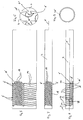
- FIG. 1 to 4 Based on Fig. 1 to 4 the basic structure of an endoscopic instrument or a tubular shaft for such an instrument according to a first preferred embodiment of the invention will be explained. It should be noted that in Fig. 1 and 2 only the tubular shaft of the Instrument is shown schematically, in Fig. 1 only some of the plurality of pipe sections 4 of the tubular shaft 2 are shown, from which the flexible part of the tubular shaft 2 is formed. It is to be understood that here further tube sections of appropriate design can be formed in the tubular shaft 2. Accordingly, in Fig. 2 only a single connection between two pipe sections 4 to illustrate the configuration of this connection shown.
- the flexible or articulated part of the tubular shaft 2 is formed from a plurality of tubular sections 4 arranged one behind the other in the axial direction X.
- the pipe sections 4 are each in positive engagement with each other at two diametrically opposite in the peripheral wall formed joints 6.
- This articulated connection is similar in structure, as for example DE 195 34 112 A1 or off DE 195 35 179 A1 is known.
- the articulated joints 6 each have a circular pin 8 on a pipe section and a corresponding circular recess 10 on an adjacent pipe section 4.
- the pin 8 engages fittingly and positively in the recess 10, so that it can rotate in the recess 10.
- the parting line 12 between the two pipe sections 4 is formed so that on one side of the circumference, starting from the two diametrically opposed articulated joints 6 wider cutouts 14 are formed. Ie. In this area, the adjacent pipe sections 4 are further spaced from each other.
- the cutouts 14 are shaped such that they expand starting from the two articulated connections 6, so that the greatest width in the longitudinal direction X is located substantially at an angular position offset by 90 ° relative to the two articulated connections 6 on the circumference of the tubular shaft 2.
- the cutouts 14 allow each two adjacent pipe sections 4 about the hinge joints 6 to the peripheral side, on which the cutouts 14 are formed, can be pivoted.
- the individual pipe sections 4 pivot in each case articulated to each other about a pivot axis which extends through the centers of the pins 8 transversely or normal to the longitudinal axis X.
- the tubular shaft curves around an external fictitious point with the radius r, wherein the radius r decreases with increasing curvature.
- the maximum curvature with the maximum pivoting angle Y of each tubular shaft 2 is achieved when, in the region of the cutouts 14, the mutually opposite end edges of the adjacent pipe sections 4 come to rest against each other.
- the parting line 12 widens on the diametrically opposite side of the cutout 14.
- the articulated connections 6 are completely formed in the wall 16 of the pipe sections 4 and der Rohrschaftes 2.
- the available cross-section is optimally utilized.
- the outer diameter of the instrument is not increased by the joints and at the same time the free lumen in the interior of the tubular shaft 2 is not reduced by the joints 6.
- the pin 8 and the recesses 10 are curved with the course of the peripheral wall 16. This causes the pins 8 and the recesses 10 on its radially inner side in the extension direction of the circumferential direction 16 have a smaller diameter than on the outside. Ie. the pins 8 are thus generally conical to the interior of the tubular shaft 2. In this way, a lateral displacement in the diameter direction or direction the pivot axis Y transverse or normal to the longitudinal axis X can be prevented.
- the individual pipe sections 4 are not completely separated from one another by the parting lines 12. Rather, the parting lines 12 are formed on the cutouts 14 diametrically opposite side so that each continuous connecting webs 18 are formed between the individual pipe sections 4, which connect adjacent pipe sections 4 together. Ie. the pipe sections 4 are not completely separated from each other, but are held together in addition to the articulated joints 6 by the connecting webs 18.
- the connecting webs 18 extend in a zigzag or S-shaped or meandering manner with respect to the longitudinal axis X between adjacent pipe sections 4. In this way, an elasticity or spring action of the connecting webs 18 in the direction of the longitudinal axis X is achieved.
- the connecting webs 18 when deflecting or pivoting of the flexible portion of the pipe section 2, in which the individual pipe sections 4, as described above, pivot about their pins 8, stretch.
- the pipe sections 4 move away from each other during pivoting, while they approach each other in the region of the cutout 14.
- the thereby taking place expansion of the connecting webs 18 takes place in that in the S-shaped course of the connecting webs 18, a bend in the region of the curves or radii of the connecting webs 18 takes place, wherein the straight sections or legs between these radii of the connecting webs 18 are further from each other remove.
- This elastic deformation of the connecting webs 18 generates a restoring or spring force, which is for a provision of the tubular shaft 2 in the in Fig. 1 shown stretched position, as soon as the force is released to deflect or at least facilitates this return movement.
- the stretched state of the connecting webs 18 is in the 10 and 11 to recognize, in which the tubular shaft 2 is deflected or curved.
- FIGS. 10 and 11 show a second embodiment of the invention, which differs from that of FIGS Fig. 1 to 4 explained embodiments only in the embodiment of the articulated joints 6 different. All other details and in particular the configuration of the connecting webs 18 are identical.
- the pins 8 ' are not circular and the recesses 10' are likewise not circular in shape.
- the pins 8 ' have a part-circular outer contour on the side at which they are connected via a web 21 with an adjacent pipe section 4. In the area facing away from the web 21, the pin 8 'is formed shortened or cut off.
- the recess 10 ' has a part-circular contour only in the region adjoining its opening, the bottom of the recess 10' is likewise cut off, in this region between the bottom of the recess 10 'and the end face of the pin 8' a free space 22 remains as clearly in the enlarged detail of Fig. 6 you can see.
- This clearance 22 allows the movement of the pin 8 'in the recess 10', wherein the adjacent pipe sections 4, as shown in the Fig. 1 to 4 explains, pivot against each other, what in 10 and 11 is shown.
- the pin 8 'and the recesses 10' as in Fig. 6 shown formed. However, the pivoting would be in the same way with the in Fig. 1 to 4 shown pin 8 work.
- FIGS. 5 to 8 and 10 and 11 shown second embodiment of the invention allows due to the not completely circular shaped joints in the longitudinal direction X narrower pipe sections 4, whereby overall smaller deflection radii can be achieved.
- FIGS. 5 and 7 the meandering course of the connecting webs 18 can be seen more clearly. It shows Fig. 5 a view in which the peripheral wall of the pipe section 2 is cut open and unwound.
- the deflection or curvature of the tubular shaft 2 is effected by a tension element 24, which extends in the longitudinal direction X in a groove 26 in the peripheral wall 16 of the tubular shaft 2 and pipe sections 4.
- This tension member 24 is attached to the distal end of the tubular shaft and, moreover, movable relative to the tubular shaft. In this way, when the pulling element 24 is pulled proximally, the tubular shaft is deflected in its movable region, which is formed by the tube sections 4, as in FIG 10 and 11 shown.
- Fig. 1 . 2 and 9 such as FIGS. 13 and 14 is this tension element 24 not shown, but it is understood that it is arranged there in a corresponding manner.
- the connecting webs 18 strive to be in their in the Fig. 1 . 5 to 8 such as 12 to 14technischzuste compassion shown starting position, ie the connecting webs 18 generate here a restoring force or a part of the restoring force.
- the connecting webs 18 between the individual pipe sections 4 provide with constant flexibility or mobility of the tubular shaft 2 for increased stability, which allows a greater power transmission, since they in particular in lateral, d. H. radial or circumferential direction with respect to the longitudinal axis X allow greater power transmission between the mutually movable pipe sections 4.
- Fig. 12 to 14 show a further embodiment of the invention, in which on the one hand, the connecting webs 18 are designed somewhat differently than in the embodiments described above.
- the connecting webs 18 have more turns and the turns are also in the Fig. 12 to 14 shown elongated initial position of the tubular shaft 2 slightly spaced from each other, wherein the column 20 between the individual turns or circumferentially extending legs of the connecting webs 18 at curvature similar to 10 and 11 be removed further from each other.
- the pins 8 and the associated recesses 10 are likewise configured with a circular contour, they have a hook-like shape near the web 21.
- the pivoting is the same as based on the Fig. 1 to 4 described.
- the main difference to the embodiments described above is that diametrically opposed to the connecting webs 18 in the wall 16 of the pipe sections 4 further connecting webs 28 between adjacent pipe sections 4 are formed.
- the connecting webs 28 are like the connecting webs 18 formed in the peripheral wall 16 of the tubular shaft 2 itself and have However, in the connecting webs 28, the turns are larger and in the rest position shown further spaced from each other, since the connecting webs 18 have an effect as a compression spring in the longitudinal direction X.
- the pipe sections 4 are pivoted about the joints 6, so that they are approximated in the region of the cutouts 14 to each other. Since the connecting webs 28 on the peripheral side, on which the recesses 14 have their greatest width, are arranged, the connecting webs 18 are thereby compressed, that is, their turns approximate each other. This follows by a bend in the region of the radii of curvature between the individual legs of the connecting webs 28.
- the connecting webs 28 Simultaneously with the elongation of the connecting webs 18, the connecting webs 28 thus generate a further restoring force, because of their elasticity, the pipe sections 4 in the region of the cutouts 14 to push apart again.
- the connecting webs 28, which connect the adjacent pipe sections 4 in one piece according to the arrangement of the connecting webs 18, ensure additional stability in the diameter or circumferential direction.
- a deflection or curvature of the tubular shaft 2 is provided only in one plane in one direction.
- the articulated connections 6 are all arranged in the same circumferential region in the longitudinal direction X on a line.
- the connecting webs 18 and 28 are arranged lying in a longitudinal direction on a line.
- FIG. 15 An example of such an embodiment is in Fig. 15 shown.
- the pipe sections 4 are interconnected so that the articulated joints 6, consisting of pin 8 and recess 10 between adjacent pipe sections 4 are alternately offset by 90 ° with respect to the longitudinal axis X are arranged.
- the normally mutually oriented pivot axes always alternate. That is, viewed in the direction of the longitudinal axis, a first pivot axis between a first and a second pipe section in a first direction, while the next pivot axis between the second and a third pipe section is rotated by 90 ° or directed with respect to the longitudinal axis X, and so on.
- the tubular shaft 2 with the cutouts 14, the articulated joints 6 and the connecting webs 18 and 28 is made of a tube by the joints 2 and the recesses and joints, which form the connecting webs 18 are cut into the pipe. This can be done for example by laser beam or electron beam cutting. In this way, it is very easy to introduce complex shapes in the wall 16 of the tubular shaft 2 and to design the individual pipe sections 4 in one piece and at the same time to ensure the mobility around the joints.
Landscapes
- Health & Medical Sciences (AREA)
- Life Sciences & Earth Sciences (AREA)
- Surgery (AREA)
- Biomedical Technology (AREA)
- Medical Informatics (AREA)
- Optics & Photonics (AREA)
- Pathology (AREA)
- Radiology & Medical Imaging (AREA)
- Biophysics (AREA)
- Engineering & Computer Science (AREA)
- Physics & Mathematics (AREA)
- Heart & Thoracic Surgery (AREA)
- Nuclear Medicine, Radiotherapy & Molecular Imaging (AREA)
- Molecular Biology (AREA)
- Animal Behavior & Ethology (AREA)
- General Health & Medical Sciences (AREA)
- Public Health (AREA)
- Veterinary Medicine (AREA)
- Endoscopes (AREA)
- Surgical Instruments (AREA)
Priority Applications (4)
| Application Number | Priority Date | Filing Date | Title |
|---|---|---|---|
| EP07007041A EP1977677B1 (fr) | 2007-04-04 | 2007-04-04 | Instrument endoscopique |
| DE502007001349T DE502007001349D1 (de) | 2007-04-04 | 2007-04-04 | Endoskopisches Instrument |
| AT07007041T ATE439798T1 (de) | 2007-04-04 | 2007-04-04 | Endoskopisches instrument |
| US12/061,688 US20080249364A1 (en) | 2007-04-04 | 2008-04-03 | Endoscopic instrument |
Applications Claiming Priority (1)
| Application Number | Priority Date | Filing Date | Title |
|---|---|---|---|
| EP07007041A EP1977677B1 (fr) | 2007-04-04 | 2007-04-04 | Instrument endoscopique |
Publications (2)
| Publication Number | Publication Date |
|---|---|
| EP1977677A1 true EP1977677A1 (fr) | 2008-10-08 |
| EP1977677B1 EP1977677B1 (fr) | 2009-08-19 |
Family
ID=38024551
Family Applications (1)
| Application Number | Title | Priority Date | Filing Date |
|---|---|---|---|
| EP07007041A Not-in-force EP1977677B1 (fr) | 2007-04-04 | 2007-04-04 | Instrument endoscopique |
Country Status (4)
| Country | Link |
|---|---|
| US (1) | US20080249364A1 (fr) |
| EP (1) | EP1977677B1 (fr) |
| AT (1) | ATE439798T1 (fr) |
| DE (1) | DE502007001349D1 (fr) |
Cited By (10)
| Publication number | Priority date | Publication date | Assignee | Title |
|---|---|---|---|---|
| WO2010030764A3 (fr) * | 2008-09-12 | 2010-05-27 | Boston Scientific Scimed, Inc. | Conduit de guidage flexible |
| WO2010102002A1 (fr) * | 2009-03-05 | 2010-09-10 | Hansen Medical, Inc. | Ensemble support blocable |
| DE102010034345A1 (de) * | 2010-08-14 | 2012-02-16 | Richard Wolf Gmbh | Endoskopisches Instrument |
| WO2013128860A1 (fr) * | 2012-02-28 | 2013-09-06 | Terumo Kabushiki Kaisha | Tube flexible pour instrument médical et instrument médical |
| US9198561B2 (en) | 2011-01-31 | 2015-12-01 | Boston Scientific Scimed, Inc. | Articulation section with locking |
| US10357320B2 (en) | 2014-08-27 | 2019-07-23 | Distalmotion Sa | Surgical system for microsurgical techniques |
| US10363055B2 (en) | 2015-04-09 | 2019-07-30 | Distalmotion Sa | Articulated hand-held instrument |
| US10413374B2 (en) | 2018-02-07 | 2019-09-17 | Distalmotion Sa | Surgical robot systems comprising robotic telemanipulators and integrated laparoscopy |
| US10874290B2 (en) | 2015-02-26 | 2020-12-29 | Stryker Corporation | Surgical instrument with articulation region |
| US12544096B2 (en) | 2019-04-01 | 2026-02-10 | Fortimedix Assets Ii B.V. | Steerable instrument comprising a hinge with a slotted structure |
Families Citing this family (56)
| Publication number | Priority date | Publication date | Assignee | Title |
|---|---|---|---|---|
| US8007506B2 (en) | 2006-06-30 | 2011-08-30 | Atheromed, Inc. | Atherectomy devices and methods |
| US8628549B2 (en) | 2006-06-30 | 2014-01-14 | Atheromed, Inc. | Atherectomy devices, systems, and methods |
| US20080045986A1 (en) | 2006-06-30 | 2008-02-21 | Atheromed, Inc. | Atherectomy devices and methods |
| US9492192B2 (en) | 2006-06-30 | 2016-11-15 | Atheromed, Inc. | Atherectomy devices, systems, and methods |
| US9314263B2 (en) | 2006-06-30 | 2016-04-19 | Atheromed, Inc. | Atherectomy devices, systems, and methods |
| US8361094B2 (en) | 2006-06-30 | 2013-01-29 | Atheromed, Inc. | Atherectomy devices and methods |
| CN101511284B (zh) | 2006-06-30 | 2011-11-09 | 阿瑟罗迈德公司 | 动脉粥样硬化切除术装置和方法 |
| US8920448B2 (en) | 2006-06-30 | 2014-12-30 | Atheromed, Inc. | Atherectomy devices and methods |
| US20090018566A1 (en) | 2006-06-30 | 2009-01-15 | Artheromed, Inc. | Atherectomy devices, systems, and methods |
| US8236016B2 (en) | 2007-10-22 | 2012-08-07 | Atheromed, Inc. | Atherectomy devices and methods |
| US8070762B2 (en) | 2007-10-22 | 2011-12-06 | Atheromed Inc. | Atherectomy devices and methods |
| US8628545B2 (en) * | 2008-06-13 | 2014-01-14 | Covidien Lp | Endoscopic stitching devices |
| US20110040308A1 (en) * | 2008-06-13 | 2011-02-17 | Ramiro Cabrera | Endoscopic Stitching Devices |
| US7918376B1 (en) | 2009-03-09 | 2011-04-05 | Cardica, Inc. | Articulated surgical instrument |
| DE102009017175B4 (de) * | 2009-04-09 | 2011-05-05 | Richard Wolf Gmbh | Verfahren zur Herstellung eines abwinkelbaren Rohrs |
| US20100270354A1 (en) * | 2009-04-22 | 2010-10-28 | Ofir Rimer | Ergonomic rotary tacker |
| US9289208B1 (en) | 2009-05-05 | 2016-03-22 | Cardica, Inc. | Articulation insert for surgical instrument |
| US8096457B1 (en) | 2009-05-05 | 2012-01-17 | Cardica, Inc. | Articulation mechanisms for surgical instrument |
| US12402960B2 (en) | 2010-10-11 | 2025-09-02 | Ecole Polytechnique Federale De Lausanne (Epfl) | Mechanical manipulator for surgical instruments |
| WO2012049623A1 (fr) | 2010-10-11 | 2012-04-19 | Ecole Polytechnique Federale De Lausanne (Epfl) | Manipulateur mécanique destiné à des instruments chirurgicaux |
| US9038880B1 (en) | 2011-04-25 | 2015-05-26 | Cardica, Inc. | Articulated surgical instrument |
| US9566048B1 (en) | 2011-04-26 | 2017-02-14 | Cardica, Inc. | Surgical instrument with discrete cammed articulation |
| US9474527B1 (en) | 2011-04-26 | 2016-10-25 | Bryan D. Knodel | Surgical instrument with discrete articulation |
| JP5715304B2 (ja) | 2011-07-27 | 2015-05-07 | エコール ポリテクニーク フェデラル デ ローザンヌ (イーピーエフエル) | 遠隔操作のための機械的遠隔操作装置 |
| CN103957825B (zh) | 2011-10-13 | 2018-12-07 | 阿瑟罗迈德公司 | 粥样斑块切除装置、系统和方法 |
| US9585546B2 (en) | 2011-11-21 | 2017-03-07 | Cook Medical Technologies Llc | Endoscope stabilization system |
| US8419720B1 (en) * | 2012-02-07 | 2013-04-16 | National Advanced Endoscopy Devices, Incorporated | Flexible laparoscopic device |
| US9204783B2 (en) * | 2012-07-20 | 2015-12-08 | Boston Scientific Scimed, Inc. | Elongate medical device with articulating portion |
| JP6220085B2 (ja) | 2014-02-03 | 2017-10-25 | ディスタルモーション エスエーDistalmotion Sa | 交換可能な遠位装置を備える機械的遠隔操作デバイス |
| EP3009104B1 (fr) * | 2014-10-14 | 2019-11-20 | St. Jude Medical, Cardiology Division, Inc. | Cathéter flexible et procédés de formation associés |
| ES2751493T3 (es) | 2014-12-05 | 2020-03-31 | Fortimedix Surgical B V | Método para fabricar un instrumento orientable y dicho instrumento orientable |
| CN105759418B (zh) * | 2014-12-19 | 2019-06-28 | 深圳市锐丽视科技有限公司 | 挠性数码内窥镜 |
| EP3232977B1 (fr) | 2014-12-19 | 2020-01-29 | DistalMotion SA | Système d'accueil pour télémanipulateur mécanique |
| EP3232974B1 (fr) | 2014-12-19 | 2018-10-24 | DistalMotion SA | Poignée articulée pour télémanipulateur mécanique |
| US10864052B2 (en) | 2014-12-19 | 2020-12-15 | Distalmotion Sa | Surgical instrument with articulated end-effector |
| DK3653145T3 (da) | 2014-12-19 | 2024-04-15 | Distalmotion Sa | Genanvendeligt kirurgisk instrument til minimalinvasive procedurer |
| WO2016097861A1 (fr) | 2014-12-19 | 2016-06-23 | Distalmotion Sa | Interface stérile pour instruments chirurgicaux articulés |
| US10568709B2 (en) | 2015-04-09 | 2020-02-25 | Distalmotion Sa | Mechanical teleoperated device for remote manipulation |
| EP4545034A3 (fr) | 2015-08-28 | 2025-07-09 | Distalmotion SA | Instrument chirurgical à force d'actionnement accrue |
| US11058503B2 (en) | 2017-05-11 | 2021-07-13 | Distalmotion Sa | Translational instrument interface for surgical robot and surgical robot systems comprising the same |
| US12376927B2 (en) | 2018-02-07 | 2025-08-05 | Distalmotion Sa | Surgical robot systems comprising robotic telemanipulators and integrated laparoscopy |
| BR112020021682A2 (pt) * | 2018-04-25 | 2022-06-07 | Innomed Five L L C | Dispositivo médico e método para aperfeiçoamento de implantação de um óvulo fertilizado durante a gestação |
| US11197665B2 (en) | 2018-08-06 | 2021-12-14 | Covidien Lp | Needle reload device for use with endostitch device |
| US12582300B2 (en) | 2019-04-08 | 2026-03-24 | Fortimedix Assets Ii B.V. | Steerable instrument comprising a detachable part |
| KR20210149102A (ko) | 2019-04-08 | 2021-12-08 | 포티메딕스 에셋츠 Ii 비.브이. | 탈착가능한 부분을 포함하는 조향가능한 기구 |
| CA3191525A1 (fr) | 2020-09-03 | 2022-03-10 | Peter T. Falkner | Dispositif medical pour la sante reproductive feminine et procede d'utilisation |
| CA3199361A1 (fr) | 2020-11-17 | 2022-05-27 | Peter T. Falkner | Dispositif medical pour empecher le reflux dans le col de l'uterus |
| US11304723B1 (en) | 2020-12-17 | 2022-04-19 | Avantec Vascular Corporation | Atherectomy devices that are self-driving with controlled deflection |
| KR102559600B1 (ko) * | 2021-04-06 | 2023-07-25 | 주식회사 로엔서지컬 | 수술도구의 비대칭 구름 관절 장치 |
| WO2022261043A1 (fr) | 2021-06-07 | 2022-12-15 | Avantec Vascular Corporation | Dispositifs d'athérectomie hybrides |
| CN113303748A (zh) * | 2021-06-07 | 2021-08-27 | 深圳市美好创亿医疗科技股份有限公司 | 一种内窥镜蛇骨、生产方法及内窥镜 |
| EP4401666A1 (fr) | 2021-09-13 | 2024-07-24 | DistalMotion SA | Instruments pour système robotique chirurgical et interfaces pour ceux-ci |
| US11844585B1 (en) | 2023-02-10 | 2023-12-19 | Distalmotion Sa | Surgical robotics systems and devices having a sterile restart, and methods thereof |
| CN116533282B (zh) * | 2023-05-06 | 2026-02-13 | 南昌华安众辉健康科技股份有限公司 | 一种多自由度机械臂 |
| WO2025038964A1 (fr) | 2023-08-16 | 2025-02-20 | Avantec Vascular Corporation | Dispositifs de thrombectomie à sollicitation latérale et verticale |
| US12414785B1 (en) | 2025-03-17 | 2025-09-16 | Avantec Vascular Corporation | Cutters with pulsating vacuum control |
Citations (4)
| Publication number | Priority date | Publication date | Assignee | Title |
|---|---|---|---|---|
| EP0535847A1 (fr) * | 1991-10-04 | 1993-04-07 | Kabushiki Kaisha Machida Seisakusho | Endoscope |
| DE19534112A1 (de) | 1995-09-14 | 1997-03-20 | Wolf Gmbh Richard | Endoskopisches Instrument |
| DE19928272A1 (de) * | 1999-06-21 | 2001-01-04 | Ep Flex Feinwerktechnik Gmbh | Elastisch biegbares Endoskoprohrteil |
| US6364828B1 (en) | 2000-01-06 | 2002-04-02 | Hubert K. Yeung | Elongated flexible inspection neck |
Family Cites Families (3)
| Publication number | Priority date | Publication date | Assignee | Title |
|---|---|---|---|---|
| JP2938486B2 (ja) * | 1989-12-28 | 1999-08-23 | 株式会社町田製作所 | 湾曲管およびその製造方法 |
| DE19535179A1 (de) * | 1995-09-22 | 1997-03-27 | Wolf Gmbh Richard | Abwinkelbares Rohr und Verfahren zu seiner Herstellung |
| US5749828A (en) * | 1995-12-22 | 1998-05-12 | Hewlett-Packard Company | Bending neck for use with invasive medical devices |
-
2007
- 2007-04-04 EP EP07007041A patent/EP1977677B1/fr not_active Not-in-force
- 2007-04-04 AT AT07007041T patent/ATE439798T1/de active
- 2007-04-04 DE DE502007001349T patent/DE502007001349D1/de active Active
-
2008
- 2008-04-03 US US12/061,688 patent/US20080249364A1/en not_active Abandoned
Patent Citations (4)
| Publication number | Priority date | Publication date | Assignee | Title |
|---|---|---|---|---|
| EP0535847A1 (fr) * | 1991-10-04 | 1993-04-07 | Kabushiki Kaisha Machida Seisakusho | Endoscope |
| DE19534112A1 (de) | 1995-09-14 | 1997-03-20 | Wolf Gmbh Richard | Endoskopisches Instrument |
| DE19928272A1 (de) * | 1999-06-21 | 2001-01-04 | Ep Flex Feinwerktechnik Gmbh | Elastisch biegbares Endoskoprohrteil |
| US6364828B1 (en) | 2000-01-06 | 2002-04-02 | Hubert K. Yeung | Elongated flexible inspection neck |
Cited By (15)
| Publication number | Priority date | Publication date | Assignee | Title |
|---|---|---|---|---|
| WO2010030764A3 (fr) * | 2008-09-12 | 2010-05-27 | Boston Scientific Scimed, Inc. | Conduit de guidage flexible |
| WO2010102002A1 (fr) * | 2009-03-05 | 2010-09-10 | Hansen Medical, Inc. | Ensemble support blocable |
| DE102010034345A1 (de) * | 2010-08-14 | 2012-02-16 | Richard Wolf Gmbh | Endoskopisches Instrument |
| US9974429B2 (en) | 2011-01-31 | 2018-05-22 | Boston Scientific Scimed, Inc. | Articulation section with locking |
| US10813538B2 (en) | 2011-01-31 | 2020-10-27 | Boston Scientific Scimed, Inc. | Articulation section with locking |
| US9198561B2 (en) | 2011-01-31 | 2015-12-01 | Boston Scientific Scimed, Inc. | Articulation section with locking |
| WO2013128860A1 (fr) * | 2012-02-28 | 2013-09-06 | Terumo Kabushiki Kaisha | Tube flexible pour instrument médical et instrument médical |
| US9113783B2 (en) | 2012-02-28 | 2015-08-25 | Terumo Kabushiki Kaisha | Flexible tube for medical instrument and medical instrument |
| US10357320B2 (en) | 2014-08-27 | 2019-07-23 | Distalmotion Sa | Surgical system for microsurgical techniques |
| US10874290B2 (en) | 2015-02-26 | 2020-12-29 | Stryker Corporation | Surgical instrument with articulation region |
| US11660101B2 (en) | 2015-02-26 | 2023-05-30 | Stryker Corporation | Surgical instrument with articulating region |
| US12245774B2 (en) | 2015-02-26 | 2025-03-11 | Stryker Corporation | Surgical instrument with articulating region |
| US10363055B2 (en) | 2015-04-09 | 2019-07-30 | Distalmotion Sa | Articulated hand-held instrument |
| US10413374B2 (en) | 2018-02-07 | 2019-09-17 | Distalmotion Sa | Surgical robot systems comprising robotic telemanipulators and integrated laparoscopy |
| US12544096B2 (en) | 2019-04-01 | 2026-02-10 | Fortimedix Assets Ii B.V. | Steerable instrument comprising a hinge with a slotted structure |
Also Published As
| Publication number | Publication date |
|---|---|
| ATE439798T1 (de) | 2009-09-15 |
| DE502007001349D1 (de) | 2009-10-01 |
| US20080249364A1 (en) | 2008-10-09 |
| EP1977677B1 (fr) | 2009-08-19 |
Similar Documents
| Publication | Publication Date | Title |
|---|---|---|
| EP1977677B1 (fr) | Instrument endoscopique | |
| EP3697283B1 (fr) | Procédé servant à fabriquer un tuyau flexible d'insertion d'un endoscope, et endoscope comprenant un tuyau flexible d'insertion | |
| EP0764423B2 (fr) | Tube pliable | |
| EP2877100B1 (fr) | Tige pour instrument médical comprenant des sections mobiles | |
| EP1604607B1 (fr) | Partie flexible d'un tube d'introduction d'un endoscope et procédé de fabrication | |
| EP2696741B1 (fr) | Dispositif de commande | |
| DE3333543C2 (fr) | ||
| DE19615940A1 (de) | Harz-Gleichlaufgelenkmanschette | |
| EP2581031A1 (fr) | Dispositif de déviation | |
| EP3787471A1 (fr) | Déflexion endoscopique comprenant un mécanisme rabattable distal | |
| EP3602709B1 (fr) | Dispositif de guidage de lignes | |
| DE102009037030A1 (de) | Schaft eines chirurgischen Instrumentes mit starrem Abschnitt | |
| DE3504824A1 (de) | Endoskop | |
| DE102015110162B4 (de) | Energieführungskette umfassend ein zwischen den Gliedern eingefügtes separates Federelement, das die benachbarten Glieder in eine Vorzugsausrichtung vorspannt | |
| EP1888960A1 (fr) | Element d'ancrage destine a des couplages de tubes | |
| DE102011009372B3 (de) | Medizinische Vorrichtung mit einer Gitterstruktur und ein Behandlungssystem mit einer derartigen Gitterstruktur | |
| WO2011018179A2 (fr) | Tige dinstrument chirurgical dotée de zones flexibles | |
| DE102011009371B3 (de) | Medizinische Vorrichtung mit einer Gitterstruktur und Behandlungssystem mit einer derartigen Vorrichtung | |
| DE102005054057B4 (de) | Bauteil | |
| EP3173038B1 (fr) | Instrument à queue | |
| DE10160922A1 (de) | Biegbares Endoskoprohrstück | |
| EP1331421A2 (fr) | Levier de changement de vitesses adapté pour empêcher le pincement du soufflet | |
| EP2803326A1 (fr) | Arbre tubulaire flexible | |
| DE29623452U1 (de) | Abwinkelbares Rohr | |
| EP2898818B1 (fr) | Instrument endoscopique |
Legal Events
| Date | Code | Title | Description |
|---|---|---|---|
| PUAI | Public reference made under article 153(3) epc to a published international application that has entered the european phase |
Free format text: ORIGINAL CODE: 0009012 |
|
| 17P | Request for examination filed |
Effective date: 20080510 |
|
| AK | Designated contracting states |
Kind code of ref document: A1 Designated state(s): AT BE BG CH CY CZ DE DK EE ES FI FR GB GR HU IE IS IT LI LT LU LV MC MT NL PL PT RO SE SI SK TR |
|
| AX | Request for extension of the european patent |
Extension state: AL BA HR MK RS |
|
| GRAP | Despatch of communication of intention to grant a patent |
Free format text: ORIGINAL CODE: EPIDOSNIGR1 |
|
| GRAS | Grant fee paid |
Free format text: ORIGINAL CODE: EPIDOSNIGR3 |
|
| AKX | Designation fees paid |
Designated state(s): AT BE BG CH CY CZ DE DK EE ES FI FR GB GR HU IE IS IT LI LT LU LV MC MT NL PL PT RO SE SI SK TR |
|
| GRAA | (expected) grant |
Free format text: ORIGINAL CODE: 0009210 |
|
| AK | Designated contracting states |
Kind code of ref document: B1 Designated state(s): AT BE BG CH CY CZ DE DK EE ES FI FR GB GR HU IE IS IT LI LT LU LV MC MT NL PL PT RO SE SI SK TR |
|
| REG | Reference to a national code |
Ref country code: GB Ref legal event code: FG4D Free format text: NOT ENGLISH |
|
| REG | Reference to a national code |
Ref country code: CH Ref legal event code: NV Representative=s name: ISLER & PEDRAZZINI AG Ref country code: CH Ref legal event code: EP |
|
| REG | Reference to a national code |
Ref country code: IE Ref legal event code: FG4D |
|
| REF | Corresponds to: |
Ref document number: 502007001349 Country of ref document: DE Date of ref document: 20091001 Kind code of ref document: P |
|
| LTIE | Lt: invalidation of european patent or patent extension |
Effective date: 20090819 |
|
| PG25 | Lapsed in a contracting state [announced via postgrant information from national office to epo] |
Ref country code: FI Free format text: LAPSE BECAUSE OF FAILURE TO SUBMIT A TRANSLATION OF THE DESCRIPTION OR TO PAY THE FEE WITHIN THE PRESCRIBED TIME-LIMIT Effective date: 20090819 Ref country code: ES Free format text: LAPSE BECAUSE OF FAILURE TO SUBMIT A TRANSLATION OF THE DESCRIPTION OR TO PAY THE FEE WITHIN THE PRESCRIBED TIME-LIMIT Effective date: 20091130 Ref country code: SE Free format text: LAPSE BECAUSE OF FAILURE TO SUBMIT A TRANSLATION OF THE DESCRIPTION OR TO PAY THE FEE WITHIN THE PRESCRIBED TIME-LIMIT Effective date: 20090819 Ref country code: IS Free format text: LAPSE BECAUSE OF FAILURE TO SUBMIT A TRANSLATION OF THE DESCRIPTION OR TO PAY THE FEE WITHIN THE PRESCRIBED TIME-LIMIT Effective date: 20091219 Ref country code: LT Free format text: LAPSE BECAUSE OF FAILURE TO SUBMIT A TRANSLATION OF THE DESCRIPTION OR TO PAY THE FEE WITHIN THE PRESCRIBED TIME-LIMIT Effective date: 20090819 |
|
| PG25 | Lapsed in a contracting state [announced via postgrant information from national office to epo] |
Ref country code: SI Free format text: LAPSE BECAUSE OF FAILURE TO SUBMIT A TRANSLATION OF THE DESCRIPTION OR TO PAY THE FEE WITHIN THE PRESCRIBED TIME-LIMIT Effective date: 20090819 Ref country code: PL Free format text: LAPSE BECAUSE OF FAILURE TO SUBMIT A TRANSLATION OF THE DESCRIPTION OR TO PAY THE FEE WITHIN THE PRESCRIBED TIME-LIMIT Effective date: 20090819 Ref country code: LV Free format text: LAPSE BECAUSE OF FAILURE TO SUBMIT A TRANSLATION OF THE DESCRIPTION OR TO PAY THE FEE WITHIN THE PRESCRIBED TIME-LIMIT Effective date: 20090819 |
|
| REG | Reference to a national code |
Ref country code: IE Ref legal event code: FD4D |
|
| PG25 | Lapsed in a contracting state [announced via postgrant information from national office to epo] |
Ref country code: CY Free format text: LAPSE BECAUSE OF FAILURE TO SUBMIT A TRANSLATION OF THE DESCRIPTION OR TO PAY THE FEE WITHIN THE PRESCRIBED TIME-LIMIT Effective date: 20090819 Ref country code: BG Free format text: LAPSE BECAUSE OF FAILURE TO SUBMIT A TRANSLATION OF THE DESCRIPTION OR TO PAY THE FEE WITHIN THE PRESCRIBED TIME-LIMIT Effective date: 20091119 Ref country code: PT Free format text: LAPSE BECAUSE OF FAILURE TO SUBMIT A TRANSLATION OF THE DESCRIPTION OR TO PAY THE FEE WITHIN THE PRESCRIBED TIME-LIMIT Effective date: 20091221 |
|
| PG25 | Lapsed in a contracting state [announced via postgrant information from national office to epo] |
Ref country code: DK Free format text: LAPSE BECAUSE OF FAILURE TO SUBMIT A TRANSLATION OF THE DESCRIPTION OR TO PAY THE FEE WITHIN THE PRESCRIBED TIME-LIMIT Effective date: 20090819 Ref country code: RO Free format text: LAPSE BECAUSE OF FAILURE TO SUBMIT A TRANSLATION OF THE DESCRIPTION OR TO PAY THE FEE WITHIN THE PRESCRIBED TIME-LIMIT Effective date: 20090819 Ref country code: CZ Free format text: LAPSE BECAUSE OF FAILURE TO SUBMIT A TRANSLATION OF THE DESCRIPTION OR TO PAY THE FEE WITHIN THE PRESCRIBED TIME-LIMIT Effective date: 20090819 Ref country code: EE Free format text: LAPSE BECAUSE OF FAILURE TO SUBMIT A TRANSLATION OF THE DESCRIPTION OR TO PAY THE FEE WITHIN THE PRESCRIBED TIME-LIMIT Effective date: 20090819 Ref country code: IE Free format text: LAPSE BECAUSE OF FAILURE TO SUBMIT A TRANSLATION OF THE DESCRIPTION OR TO PAY THE FEE WITHIN THE PRESCRIBED TIME-LIMIT Effective date: 20090819 |
|
| PG25 | Lapsed in a contracting state [announced via postgrant information from national office to epo] |
Ref country code: SK Free format text: LAPSE BECAUSE OF FAILURE TO SUBMIT A TRANSLATION OF THE DESCRIPTION OR TO PAY THE FEE WITHIN THE PRESCRIBED TIME-LIMIT Effective date: 20090819 |
|
| PLBE | No opposition filed within time limit |
Free format text: ORIGINAL CODE: 0009261 |
|
| STAA | Information on the status of an ep patent application or granted ep patent |
Free format text: STATUS: NO OPPOSITION FILED WITHIN TIME LIMIT |
|
| 26N | No opposition filed |
Effective date: 20100520 |
|
| PG25 | Lapsed in a contracting state [announced via postgrant information from national office to epo] |
Ref country code: GR Free format text: LAPSE BECAUSE OF FAILURE TO SUBMIT A TRANSLATION OF THE DESCRIPTION OR TO PAY THE FEE WITHIN THE PRESCRIBED TIME-LIMIT Effective date: 20091120 |
|
| PG25 | Lapsed in a contracting state [announced via postgrant information from national office to epo] |
Ref country code: MC Free format text: LAPSE BECAUSE OF NON-PAYMENT OF DUE FEES Effective date: 20100430 |
|
| PG25 | Lapsed in a contracting state [announced via postgrant information from national office to epo] |
Ref country code: IT Free format text: LAPSE BECAUSE OF NON-PAYMENT OF DUE FEES Effective date: 20100404 |
|
| PG25 | Lapsed in a contracting state [announced via postgrant information from national office to epo] |
Ref country code: MT Free format text: LAPSE BECAUSE OF FAILURE TO SUBMIT A TRANSLATION OF THE DESCRIPTION OR TO PAY THE FEE WITHIN THE PRESCRIBED TIME-LIMIT Effective date: 20090819 |
|
| PG25 | Lapsed in a contracting state [announced via postgrant information from national office to epo] |
Ref country code: HU Free format text: LAPSE BECAUSE OF FAILURE TO SUBMIT A TRANSLATION OF THE DESCRIPTION OR TO PAY THE FEE WITHIN THE PRESCRIBED TIME-LIMIT Effective date: 20100220 |
|
| PG25 | Lapsed in a contracting state [announced via postgrant information from national office to epo] |
Ref country code: TR Free format text: LAPSE BECAUSE OF FAILURE TO SUBMIT A TRANSLATION OF THE DESCRIPTION OR TO PAY THE FEE WITHIN THE PRESCRIBED TIME-LIMIT Effective date: 20090819 |
|
| REG | Reference to a national code |
Ref country code: AT Ref legal event code: MM01 Ref document number: 439798 Country of ref document: AT Kind code of ref document: T Effective date: 20120404 |
|
| PG25 | Lapsed in a contracting state [announced via postgrant information from national office to epo] |
Ref country code: AT Free format text: LAPSE BECAUSE OF NON-PAYMENT OF DUE FEES Effective date: 20120404 |
|
| REG | Reference to a national code |
Ref country code: FR Ref legal event code: PLFP Year of fee payment: 10 |
|
| REG | Reference to a national code |
Ref country code: FR Ref legal event code: PLFP Year of fee payment: 11 |
|
| REG | Reference to a national code |
Ref country code: FR Ref legal event code: PLFP Year of fee payment: 12 |
|
| PGFP | Annual fee paid to national office [announced via postgrant information from national office to epo] |
Ref country code: LU Payment date: 20200420 Year of fee payment: 14 Ref country code: NL Payment date: 20200420 Year of fee payment: 14 Ref country code: FR Payment date: 20200421 Year of fee payment: 14 Ref country code: CH Payment date: 20200423 Year of fee payment: 14 |
|
| PGFP | Annual fee paid to national office [announced via postgrant information from national office to epo] |
Ref country code: GB Payment date: 20200423 Year of fee payment: 14 Ref country code: IT Payment date: 20200423 Year of fee payment: 14 Ref country code: BE Payment date: 20200420 Year of fee payment: 14 |
|
| REG | Reference to a national code |
Ref country code: DE Ref legal event code: R084 Ref document number: 502007001349 Country of ref document: DE |
|
| REG | Reference to a national code |
Ref country code: NL Ref legal event code: MM Effective date: 20210501 |
|
| GBPC | Gb: european patent ceased through non-payment of renewal fee |
Effective date: 20210404 |
|
| PG25 | Lapsed in a contracting state [announced via postgrant information from national office to epo] |
Ref country code: LU Free format text: LAPSE BECAUSE OF NON-PAYMENT OF DUE FEES Effective date: 20210404 |
|
| REG | Reference to a national code |
Ref country code: BE Ref legal event code: MM Effective date: 20210430 |
|
| PG25 | Lapsed in a contracting state [announced via postgrant information from national office to epo] |
Ref country code: CH Free format text: LAPSE BECAUSE OF NON-PAYMENT OF DUE FEES Effective date: 20210430 Ref country code: LI Free format text: LAPSE BECAUSE OF NON-PAYMENT OF DUE FEES Effective date: 20210430 Ref country code: GB Free format text: LAPSE BECAUSE OF NON-PAYMENT OF DUE FEES Effective date: 20210404 Ref country code: FR Free format text: LAPSE BECAUSE OF NON-PAYMENT OF DUE FEES Effective date: 20210430 |
|
| PG25 | Lapsed in a contracting state [announced via postgrant information from national office to epo] |
Ref country code: NL Free format text: LAPSE BECAUSE OF NON-PAYMENT OF DUE FEES Effective date: 20210501 |
|
| PG25 | Lapsed in a contracting state [announced via postgrant information from national office to epo] |
Ref country code: BE Free format text: LAPSE BECAUSE OF NON-PAYMENT OF DUE FEES Effective date: 20210430 |
|
| PG25 | Lapsed in a contracting state [announced via postgrant information from national office to epo] |
Ref country code: IT Free format text: LAPSE BECAUSE OF NON-PAYMENT OF DUE FEES Effective date: 20210430 |
|
| PGFP | Annual fee paid to national office [announced via postgrant information from national office to epo] |
Ref country code: DE Payment date: 20230421 Year of fee payment: 17 |
|
| REG | Reference to a national code |
Ref country code: DE Ref legal event code: R119 Ref document number: 502007001349 Country of ref document: DE |
|
| PG25 | Lapsed in a contracting state [announced via postgrant information from national office to epo] |
Ref country code: DE Free format text: LAPSE BECAUSE OF NON-PAYMENT OF DUE FEES Effective date: 20241105 |
|
| PG25 | Lapsed in a contracting state [announced via postgrant information from national office to epo] |
Ref country code: DE Free format text: LAPSE BECAUSE OF NON-PAYMENT OF DUE FEES Effective date: 20241105 |