EP1977702B1 - Vorrichtung zur Faltung und Befestigung von Magengewebe - Google Patents
Vorrichtung zur Faltung und Befestigung von Magengewebe Download PDFInfo
- Publication number
- EP1977702B1 EP1977702B1 EP08251296A EP08251296A EP1977702B1 EP 1977702 B1 EP1977702 B1 EP 1977702B1 EP 08251296 A EP08251296 A EP 08251296A EP 08251296 A EP08251296 A EP 08251296A EP 1977702 B1 EP1977702 B1 EP 1977702B1
- Authority
- EP
- European Patent Office
- Prior art keywords
- tissue
- jaws
- plication
- clip
- fold
- Prior art date
- Legal status (The legal status is an assumption and is not a legal conclusion. Google has not performed a legal analysis and makes no representation as to the accuracy of the status listed.)
- Not-in-force
Links
- 230000002496 gastric effect Effects 0.000 title description 30
- 239000012636 effector Substances 0.000 claims abstract description 23
- 238000003780 insertion Methods 0.000 claims abstract description 9
- 230000037431 insertion Effects 0.000 claims abstract description 9
- 238000004891 communication Methods 0.000 claims abstract description 3
- 239000012530 fluid Substances 0.000 claims abstract description 3
- 210000000056 organ Anatomy 0.000 claims abstract description 3
- 238000012800 visualization Methods 0.000 claims description 3
- 238000000034 method Methods 0.000 description 25
- 210000002784 stomach Anatomy 0.000 description 10
- 208000008589 Obesity Diseases 0.000 description 9
- 208000012696 congenital leptin deficiency Diseases 0.000 description 8
- 208000001022 morbid obesity Diseases 0.000 description 8
- 206010025476 Malabsorption Diseases 0.000 description 3
- 208000004155 Malabsorption Syndromes Diseases 0.000 description 3
- 230000004323 axial length Effects 0.000 description 3
- 230000000717 retained effect Effects 0.000 description 3
- 238000012546 transfer Methods 0.000 description 3
- 238000010521 absorption reaction Methods 0.000 description 2
- 230000000712 assembly Effects 0.000 description 2
- 238000000429 assembly Methods 0.000 description 2
- 238000011038 discontinuous diafiltration by volume reduction Methods 0.000 description 2
- 230000000694 effects Effects 0.000 description 2
- 239000000463 material Substances 0.000 description 2
- 230000002040 relaxant effect Effects 0.000 description 2
- 238000001356 surgical procedure Methods 0.000 description 2
- 208000008279 Dumping Syndrome Diseases 0.000 description 1
- 208000019693 Lung disease Diseases 0.000 description 1
- 208000002720 Malnutrition Diseases 0.000 description 1
- 208000032395 Post gastric surgery syndrome Diseases 0.000 description 1
- 208000006011 Stroke Diseases 0.000 description 1
- 230000003466 anti-cipated effect Effects 0.000 description 1
- 238000013459 approach Methods 0.000 description 1
- 238000007681 bariatric surgery Methods 0.000 description 1
- 238000010276 construction Methods 0.000 description 1
- 238000009223 counseling Methods 0.000 description 1
- 206010012601 diabetes mellitus Diseases 0.000 description 1
- 235000005911 diet Nutrition 0.000 description 1
- 230000000378 dietary effect Effects 0.000 description 1
- 210000003238 esophagus Anatomy 0.000 description 1
- 210000001035 gastrointestinal tract Anatomy 0.000 description 1
- 208000019622 heart disease Diseases 0.000 description 1
- 239000007943 implant Substances 0.000 description 1
- 238000002513 implantation Methods 0.000 description 1
- 238000007373 indentation Methods 0.000 description 1
- 208000014674 injury Diseases 0.000 description 1
- 210000000936 intestine Anatomy 0.000 description 1
- 230000007794 irritation Effects 0.000 description 1
- 210000001630 jejunum Anatomy 0.000 description 1
- 230000007774 longterm Effects 0.000 description 1
- 230000001071 malnutrition Effects 0.000 description 1
- 235000000824 malnutrition Nutrition 0.000 description 1
- 230000013011 mating Effects 0.000 description 1
- 239000007769 metal material Substances 0.000 description 1
- 238000012986 modification Methods 0.000 description 1
- 230000004048 modification Effects 0.000 description 1
- 208000015380 nutritional deficiency disease Diseases 0.000 description 1
- 235000020824 obesity Nutrition 0.000 description 1
- 239000002245 particle Substances 0.000 description 1
- 230000000737 periodic effect Effects 0.000 description 1
- 230000000144 pharmacologic effect Effects 0.000 description 1
- 230000002265 prevention Effects 0.000 description 1
- 238000012545 processing Methods 0.000 description 1
- 230000005855 radiation Effects 0.000 description 1
- 230000002441 reversible effect Effects 0.000 description 1
- 210000000813 small intestine Anatomy 0.000 description 1
- 230000001954 sterilising effect Effects 0.000 description 1
- 238000004659 sterilization and disinfection Methods 0.000 description 1
- 238000006467 substitution reaction Methods 0.000 description 1
- 238000002560 therapeutic procedure Methods 0.000 description 1
- 230000008733 trauma Effects 0.000 description 1
Images









Classifications
-
- A—HUMAN NECESSITIES
- A61—MEDICAL OR VETERINARY SCIENCE; HYGIENE
- A61B—DIAGNOSIS; SURGERY; IDENTIFICATION
- A61B17/00—Surgical instruments, devices or methods
- A61B17/12—Surgical instruments, devices or methods for ligaturing or otherwise compressing tubular parts of the body, e.g. blood vessels or umbilical cord
- A61B17/128—Surgical instruments, devices or methods for ligaturing or otherwise compressing tubular parts of the body, e.g. blood vessels or umbilical cord for applying or removing clamps or clips
- A61B17/1285—Surgical instruments, devices or methods for ligaturing or otherwise compressing tubular parts of the body, e.g. blood vessels or umbilical cord for applying or removing clamps or clips for minimally invasive surgery
-
- A—HUMAN NECESSITIES
- A61—MEDICAL OR VETERINARY SCIENCE; HYGIENE
- A61F—FILTERS IMPLANTABLE INTO BLOOD VESSELS; PROSTHESES; DEVICES PROVIDING PATENCY TO, OR PREVENTING COLLAPSING OF, TUBULAR STRUCTURES OF THE BODY, e.g. STENTS; ORTHOPAEDIC, NURSING OR CONTRACEPTIVE DEVICES; FOMENTATION; TREATMENT OR PROTECTION OF EYES OR EARS; BANDAGES, DRESSINGS OR ABSORBENT PADS; FIRST-AID KITS
- A61F5/00—Orthopaedic methods or devices for non-surgical treatment of bones or joints; Nursing devices ; Anti-rape devices
- A61F5/0003—Apparatus for the treatment of obesity; Anti-eating devices
- A61F5/0013—Implantable devices or invasive measures
- A61F5/0083—Reducing the size of the stomach, e.g. gastroplasty
- A61F5/0086—Reducing the size of the stomach, e.g. gastroplasty using clamps, folding means or the like
-
- A—HUMAN NECESSITIES
- A61—MEDICAL OR VETERINARY SCIENCE; HYGIENE
- A61B—DIAGNOSIS; SURGERY; IDENTIFICATION
- A61B17/00—Surgical instruments, devices or methods
- A61B17/10—Surgical instruments, devices or methods for applying or removing wound clamps, e.g. containing only one clamp or staple; Wound clamp magazines
-
- A—HUMAN NECESSITIES
- A61—MEDICAL OR VETERINARY SCIENCE; HYGIENE
- A61B—DIAGNOSIS; SURGERY; IDENTIFICATION
- A61B17/00—Surgical instruments, devices or methods
- A61B17/12—Surgical instruments, devices or methods for ligaturing or otherwise compressing tubular parts of the body, e.g. blood vessels or umbilical cord
- A61B17/122—Clamps or clips, e.g. for the umbilical cord
-
- A—HUMAN NECESSITIES
- A61—MEDICAL OR VETERINARY SCIENCE; HYGIENE
- A61B—DIAGNOSIS; SURGERY; IDENTIFICATION
- A61B17/00—Surgical instruments, devices or methods
- A61B17/28—Surgical forceps
- A61B17/29—Forceps for use in minimally invasive surgery
- A61B2017/2926—Details of heads or jaws
-
- A—HUMAN NECESSITIES
- A61—MEDICAL OR VETERINARY SCIENCE; HYGIENE
- A61B—DIAGNOSIS; SURGERY; IDENTIFICATION
- A61B17/00—Surgical instruments, devices or methods
- A61B17/30—Surgical pincettes, i.e. surgical tweezers without pivotal connections
- A61B2017/306—Surgical pincettes, i.e. surgical tweezers without pivotal connections holding by means of suction
Definitions
- the present invention relates in general to a bariatric treatment device and, more particularly, to a device for transorally plicating and fastening areas of gastric tissue to achieve a gastric volume reduction.
- morbid obesity The percentage of the world's population suffering from morbid obesity is steadily increasing. Severely obese persons are susceptible to increased risk of heart disease, stroke, diabetes, pulmonary disease, and accidents. Because of the effect of morbid obesity to the life of the patient, methods of treating morbid obesity are being researched.
- Most surgical procedures for treatment of morbid obesity may generally be classified as either being directed toward the prevention of absorption of food (malabsorption), or restriction of stomach to make the patient feel full (gastric restriction)
- malabsorption and gastric restriction technique is the gastric bypass.
- the stomach is horizontally divided into two isolated pouches, with the upper pouch having a small food capacity.
- the upper pouch is connected to the small intestine, or jejunum, through a small stoma, which restricts the processing of food by the greatly reduced useable stomach. Since food bypass much of the intestines, the amount of absorption of food is greatly reduced.
- a gastric band is operatively placed to encircle the stomach. This divides the stomach into two parts with a stoma in-between. An upper portion, or a pouch, which is relatively small, and a lower portion which is relatively large. The small partitioned portion of the stomach effectively becomes the patients new stomach, requiring very little food to make the patient feel full.
- US 2002/0082621 A1 discloses a device according to the preamble of claim 1.
- WO 02/096327A discloses tools and methods for the treatment of obesity.
- a device for creating a plication within a hollow organ has an elongated member with distal and proximal ends. The distal end is for insertion into a body cavity.
- the elongated member has an end effector at its distal end.
- the end effector includes an outer cylinder having at least one opening in its cylindrical wall.
- the end effector also has an inner cylinder having at least one opening in its cylindrical.
- the inner cylinder is at least partially disposed within the outer cylinder such that the apertures can at least partially overlap.
- the cylinders are rotatable with respect to each other.
- the device includes a tubular channel running through the elongated member which is in fluid communication with the end effector.
- the channel has a vacuum source attached at its proximal end.
- the device further includes a fastening means which is a wire clip, and which is contoured to surround the perimeter of the end effector.
- FIG. 1 is a perspective view of a tissue plicating device
- FIG. 2 is a diagrammatic view of the tissue plication device of FIG. 1 , shown pushed into a tissue area in a gastric cavity;
- FIG. 3A is a more detailed, perspective view of the distal end of the tissue plicating device of FIG. 1 , showing the tip of the device in an initial, closed position;
- FIG. 3B is a more detailed, perspective view of the distal end of the tissue plicating device of FIG. 1 , showing the tip of the device in a partially open position;
- FIG. 3C is a more detailed, perspective view of the distal end of the tissue plicating device of FIG. 1 , showing the tip of the device in a fully open, operative position;
- FIG. 4 is a diagrammatic view of the tissue plication device of FIG. 1 , showing the device creating a fold in an area of tissue;
- FIG. 5 is a perspective view of a second alternative for the folding member of the tissue plicating device
- FIG. 6 is an additional perspective view of the folding member of FIG. 5 , showing the folding member jaws in a fully open position;
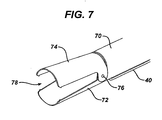
- FIG. 7 is a perspective view of a third alternative for the folding member of the present invention.
- FIG. 8 is a perspective view of a fourth alternative for the folding member
- FIG. 9 is a perspective view of a fifth alternative for the folding member.
- FIG. 10A is a perspective view of a sixth alternative for the folding member showing a retractable jaw of the member in a first, retracted position;
- FIG. 10B is an additional perspective of the sixth folding member alternative, showing the retractable jaw in a forward projected position
- FIG. 11 shows an embodiment for the tissue plicating device of the present invention, in which the device comprises a tissue fastening member
- FIG. 12A is a more detailed, perspective view of the fastener embodiment shown in FIG. 11 ;
- FIG. 12B is a top view of the fastener embodiment shown in FIG. 11 ;
- FIG. 12C is an end view of the fastener embodiment shown in FIG. 11 ;
- FIG. 13 is a diagrammatic view of the tissue plication device of FIG. 11 , showing the device pushed into a tissue wall within a gastric cavity;
- FIG. 14 is a diagrammatic view of the tissue plication device of FIG. 11 , showing the device placing a fastener on a tissue fold;
- FIG. 15 is a diagrammatic view similar to FIG. 14 , showing the gastric cavity subsequent to folding and placement of a fastening member;
- FIG. 16A is a perspective view of an alternative embodiment for a tissue plication fastener
- FIG. 16B is a top view of the alternative fastener shown in FIG. 16A ;
- FIG. 16C is a side view of the alternative fastener shown in FIG. 16A ;
- FIG. 16D is an end view of the alternative fastener shown in FIG. 16A ;
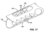
- FIG. 17 is a perspective view of a third embodiment for a tissue fastener in accordance with the present invention.
- FIG. 18A is a perspective view of a fourth embodiment for a tissue fastening device
- FIG. 18B is a side view of the tissue fastening device shown in FIG. 18A ;
- FIG. 18C is an end view of the tissue fastening device shown in FIG. 18A ;
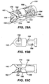
- FIG. 19A is a perspective view of a fifth embodiment for a tissue fastening device
- FIG. 19B is a top view of the tissue fastening device shown in FIG. 19A ;
- FIG. 19C is a side view of the tissue fastening device shown in FIG. 19A ;
- FIG. 20A is a perspective view of a sixth embodiment for a tissue fastening device
- FIG. 20B is a top view of the tissue fastening device shown in FIG. 20A ;
- FIG. 20C is a side view of the tissue fastening device shown in FIG. 20A ;
- FIG. 21 is a perspective view of a seventh embodiment for a tissue fastening device of the present invention.
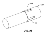
- FIG. 22 is a perspective view of an additional alternative for the tissue plicating implant device of the present invention.
- FIG. 23 is a view similar to that shown in FIG. 22 but showing the device in its partially deployed position
- FIG. 24 is an exploded view of the device shown in FIG. 22 ;
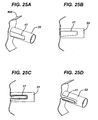
- FIG 25A-25C are simplified perspective views of the device shown in FIG. 1 actually acquiring tissue and forming a plication.
- the present invention pertains to an endoscopic tissue plicating and fastening device for forming tissue folds within a gastric cavity in order to reduce the volume of the cavity.
- the present invention reduces the surface area within the cavity, thereby reducing the available food volume in the stomach.
- the present invention provides a simplified tissue plicating procedure in which the tissue folds are retained by either staples, or absorbable or removable clips, thus enabling the procedure to be easily reversed. Additionally, the present invention enables large areas of the stomach cavity to be plicated transorally, thus providing an effective bariatric treatment without the trauma encountered in an open surgery plication procedure.
- FIG. 1 illustrates a tissue plicating device 20.
- Tissue plicating device 20 comprises a folding member or end effector 22 connected at the distal end of an elongated member such as a flexible endoscope 24.
- Folding member 22 includes an open distal end 26 for receiving tissue drawn into the device.
- a connecting member 30 extends between folding member 22 and endoscope 24 to securely attach the folding member to the endoscope, so that the folding member is transferred along with the endoscope during transoral insertion and removal.
- Endoscope 24 includes a side port 32 providing access to a working channel within the endoscope, as well as visualization capabilities for guiding device 20 to a desired location within a gastric cavity. Vacuum is provided to folding member 22 for drawing tissue into the device.
- FIG. 1 illustrates a tissue plicating device 20.
- vacuum is provided through a separate vacuum line 34, which extends along the exterior length of endoscope 24.
- Vacuum line 34 connects at a proximal end 36 to a conventional vacuum source (not shown).
- vacuum can be provided to folding member 22 through the working channel of endoscope 24, rather than through a separate exterior vacuum line.
- Control of device 20 is provided through a connection 40 that extends along the exterior length of endoscope 24.
- Control connection 40 is attached at a distal end to folding member 22 for moving the member between an open and closed position, as will be described in more detail below.
- control connection 40 attaches to a control assembly (not shown).
- the control assembly is operated by a surgeon in order to perform tissue folding and securing procedures.
- a number of different types of control assemblies may be utilized to drive the folding member of the present invention. These assemblies may include a push/pull cabling system, a rotational cable/rod, a hydraulic actuation system, or an electromagnetic actuation system.
- device 20 is inserted transorally through an esophageal overtube 42 and into a gastric cavity 44, as shown in FIG. 2 .
- Folding member 22 is inserted through the esophagus and into the gastric cavity in an initial, closed position. This closed position allows for easier transfer into the gastric cavity.
- endoscope 24 is used to visualize the interior of cavity 44 (with a visualization device common to most endoscopes) and select the appropriate location for placement of a fold.
- the distal tip of folding member 22 is pushed into the tissue wall 46 at the selected location, as shown in FIG. 2 .
- Vacuum is then applied through vacuum line 34 to draw adjacent tissue into device 20.
- the control assembly rotates folding member 22 into an open, tissue receiving position.
- FIGS. 3A-3C illustrate the distal end of folding member 22 in greater detail as the member is rotated from a closed to an open position.
- folding member 22 comprises a pair of concentric cylinders 50 (inner cylinder), 52 (outer cylinder) each having an open distal end 26.
- Lateral slots or apertures 54 extend from open end 26 into opposing sides of each of the cylinders 50, 52.
- One edge of each of the slots 54 is angled slightly inwardly, as indicated at 56, in order to guide tissue into the slots.
- cylinders 50, 52 are positioned with the lateral slots 54 of the cylinders offset, thereby substantially closing the sides of the member.
- one of the cylinders 50, 52 is rotated relative to the other cylinder to open lateral slots 54, as shown in FIG. 3B .
- vacuum is applied to the tissue wall through distal opening 26 to pull the tissue into slots 54.
- FIG. 3C tissue fills slots 54 as the upper and lower layers of the tissue are folded together in a serosa to serosa configuration.
- FIG. 4 illustrates device 20 with tissue wall 46 folded into a fully open folding member 22 to form a plication 58.
- a tissue fastening mechanism such as, for example, a stapler (not shown)
- endoscope 24 is passed through the working channel of endoscope 24 to secure the plication.
- the end effector could be detached from the endoscope after the plication is made to secure the tissue together. This could be accomplished by any number of means known to those skilled in the art, such as placing matching detents on the cylinders which latch when the end effector is in its closed position.
- plication 58 After plication 58 is secured, the fastening mechanism is withdrawn, and the vacuum through line 34 turned off, to release the plication from folding member 22. Following release of the plication, cylinders 50, 52 are rotated to close folding member 22. Endoscope 24 and folding member 22 may then be moved to another location within the gastric cavity to form an additional plication. Once in the new location, vacuum is again applied to folding member 22 as the member is rotated open, to draw tissue into a fold within lateral slots 54. After folding, the tissue is again secured, the vacuum turned off, and folding member 22 rotated to a closed position. This procedure for forming a tissue plication may be repeated at multiple locations within the gastric cavity until the desired number of plications have been completed. In a typical bariatric procedure, it is anticipated that 5 or 6 plications would be formed within the gastric cavity to produce approximately a 50% volume reduction. A lesser or greater number of plications may be formed, however, depending upon the particular needs of the patient.
- FIGS. 5 and 6 illustrate an alternative for the folding member of the present invention.
- the tissue folding member comprises a pair of semi-circular reciprocating jaws 60 connected at the distal end of endoscope 24 by connecting member 30. Jaws 60 are attached together by pivot pins 62 to open and close relative to a distal opening 64. Each of jaws 60 is operated through control connection 40 to pivot outwardly relative to the axial centerline of the folding member. Vacuum is applied to the interior area between jaws 60 by vacuum line 34. Jaws 60 are initially in a closed position during transoral insertion into the gastric cavity.
- jaws 60 are pushed into the tissue wall at the desired plication location, in a manner similar to that described above with respect to the first folding member embodiment.
- the vacuum source is turned on, and the jaws are slowly opened to fold the tissue wall into the opening between the jaws.
- a pair of teeth 66 may be located adjacent the outer edge of each jaw 60 for grasping and holding the folding tissue in the jaws until the plication is secured and released.
- a tissue securing device may be passed through the working channel of endoscope 24 to secure the fold.
- the tissue folding member may comprise a set of tissue grasping jaws in which one jaw rotates relative to a fixed second jaw.
- the folding member comprises a cylinder 70 with the upper portion cutaway to form a fixed lower jaw 72.
- Lower jaw 72 extends axially from cylinder 70 as a semi-circular distal projection.
- a mating, semi-circular upper jaw 74 is attached to the folding member by pivot pins 76.
- Upper jaw 74 extends in a parallel fashion to lower jaw extension 72.
- vacuum is applied through the interior of cylinder 70 to draw the tissue wall proximally into an opening 78 between jaws 72, 74.
- upper jaw 74 is pivoted away from lower jaw 72, via control connection 40, to increase the size of the tissue opening and allow the tissue wall to fold into the opening.
- upper jaw 74 is pivoted to a fully open position, the folded tissue between the jaws is secured by a fastening device passed through endoscope 24. Vacuum is then turned off, and the secured plication released from the folding member.
- FIG. 8 illustrates another alternative for the folding member of the present invention.
- tissue folding is accomplished through a cylindrical end piece 80 attached by connecting member 30 at the distal tip of endoscope 24.
- End piece 80 includes a side slot 82 that extends proximally from an open distal end 84.
- Vacuum is applied through the interior of end piece 80 to draw tissue into open end 84 and up into slot 82.
- the walls of the tissue are folded together.
- a securing device may be passed through endoscope 24 to affix the tissue layers together Following tissue securement, the vacuum through line 34 is turned off to release the tissue plication from distal end 84.
- FIG. 9 shows yet another alternative for a tissue folding member , in which the member comprises a cylinder 90 having an open distal end 92 and a pair of side slot openings 94, 96.
- vacuum is applied through cylinder 90 and open distal end 92 to draw tissue into the device.
- the tissue expands up into side slots 94, 96.
- a fold is formed therein.
- a securing device may be passed through endoscope 24 to affix the tissue layers together.
- FIGS. 8 and 9 both comprise a fixed cylindrical body for drawing tissue into the device. Accordingly, these alternatives eliminate the need to extend a control connection 40 to the distal end of the device in order to operate the folding member.
- FIGS. 10A and 10B illustrate an additional alternative for a tissue folding member of the present invention.
- the folding member comprises a cylindrical piece 100 having a first, fixed jaw 102 projecting from an open end 104.
- a second, retractable jaw 106 extends into open end 104 on a side opposite fixed jaw 102.
- the distal tip 107 of the folding member is pushed into the gastric tissue wall at a desired plication location.
- Second jaw 106 is initially in a retracted position, shown in FIG. 10A , when the folding member is positioned against the tissue wall. Once tissue contact is made at the desired location, vacuum from line 34 is applied through the interior of cylinder 100 to pull tissue onto first jaw 102.
- second jaw 106 is moved distally, substantially parallel to first jaw 102, to pull the tissue outward and fold the tissue over the first jaw.
- the tip of second jaw 106 is radii smooth, as indicated by reference numeral 108, to facilitate the second jaw sliding over the tissue.
- a fastening mechanism is passed through the interior of cylinder 100 to fasten the plication.
- the vacuum through cylinder 100 is turned off, and jaw 106 retracted back into cylinder 100.
- the folding member may then be moved to a new tissue location to form additional plications, or removed from the patient.
- the device further comprises a fastening means for securing the tissue plication subsequent to tissue folding.
- a fastening means for securing the tissue plication subsequent to tissue folding.
- Use of a fastening means on device 20 eliminates the need to pass a separate tissue fastening mechanism through endoscope 24 after folding in order to secure the plication.
- a fastening member 110 is disposed adjacent the distal end of the device for transfer from the device to a plication after folding. Fastening member 110 is held sufficiently secure on device 20 to be passed along with endoscope 24 and folding member 22 into the gastric cavity, yet is removable through control connection 40 at the end of a tissue folding procedure to secure a plication.
- FIG. 11 a fastening member 110 is disposed adjacent the distal end of the device for transfer from the device to a plication after folding. Fastening member 110 is held sufficiently secure on device 20 to be passed along with endoscope 24 and folding member 22 into the gastric cavity, yet is removable through control connection 40 at the end of a tissue
- the fastening member is a wire clip 110 which is retained on connecting member 30 just proximal of the tissue folding slots 54 in folding member 22.
- Wire clip 110 is contoured to surround the perimeter of connecting member 30 and folding member 22 and be retained thereon during device insertion.
- wire clip 110 comprises a continuous length of thin gauge wire.
- the proximal end of clip 110 is shaped on opposing sides in a spring form, indicated by reference numeral 112, to assist in generating sufficient force to clamp onto the folded tissue.
- the wire is shaped into a pair of telescoping jaws 114, 116, as shown in FIG. 12B .
- Jaws 114, 116 extend distally from spring forms 112 in a parallel fashion to slide along the upper and lower surfaces of a tissue fold.
- the distal tips 118 of jaws 114, 116 may flare outwardly from the axial centerline of clip 110 to facilitate lead-in of the clip onto a tissue fold. As shown in FIG.
- clip 110 has a substantially circular cross-section to conform to the shape of connecting member 30 to aid in retaining the clip on the folding member during the transoral insertion of device 20.
- control connection 40 engages clip 110 to release the clip from folding member 22, and slide the clip onto the tissue fold.
- FIG.13 illustrates device 20 with wire clip 110 disposed thereon engaging a gastric tissue wall prior to folding.
- clip 110 is carried on connecting member 30 as device 20 is inserted into gastric cavity 44 and pushed into tissue wall 46 at a desired plication location.
- FIG. 14 similarly illustrates gastric cavity 44 as vacuum is applied through folding member 22 to draw tissue wall 46 into a fold.
- jaws 114, 116 of clip 110 expand and move over folding member 22 to initially engage the tissue fold.
- jaws 114, 116 clamp down on plication 58. Jaws 114, 116 clamp onto plication 58 due to the energy stored in spring forms 112.
- the vacuum to folding member 22 is turned off, and the remainder of device 20 moved away from the plication location, leaving the fastened plication as shown in FIG. 15 .
- FIGS. 16A-16D illustrate an alternative embodiment for a tissue fastener usable with folding member 22 of the invention.
- the fastener comprises a continuous wire clip 120 formed into a pair of parallel extending jaws 122, 124 that engage a tissue fold.
- Jaws 122, 124 each comprise a pair of evenly spaced wire lengths that are bent at 180° angles at the proximal ends of the clip, as indicated by reference numeral 126.
- the distal ends of jaws 122, 124 flare outwardly, as indicated at 128, to enhance lead-in of the clip onto the tissue fold
- Clip 120 also comprises one or more wire shapes for preventing slippage of the clip along the tissue fold. As shown in FIG.
- these wire shapes may comprise indentations or "teeth" 130 placed along the length of either of jaws 122 or 124.
- clip 120 has a substantially circular cross-section that follows the contour of connecting member 30 and folding member 22 to retain the clip on device 20 until released onto a tissue fold through control connection 40.
- FIG. 17 illustrates a third embodiment for a tissue fastener in accordance with the present invention.
- the tissue fastener comprises a tubular-shaped clip 132.
- Clip 132 has an inner diameter that is sized to contour the outer perimeter of connecting member 30 to retain the clip thereon until released onto a fold.
- Clip 132 has an open distal end 134 for engaging a tissue fold.
- a pair of semi-circular jaws 136, 140 extends along the axial length of clip 132 for engaging a tissue fold as the clip is transferred onto the fold through control connection 40. Jaws 136, 140 each have a rounded distal end for facilitating transfer of clip 132 onto the tissue fold.
- a plurality of teeth extend from the inwardly facing edges of jaws 136, 140 to grasp and hold tissue within the clip, thereby preventing the clip from dislodging from the tissue fold after fastening.
- Clip 132 can be manufactured from either a plastic or a metallic material. Clip 132 can also be made from absorbable material where it will dissolve away after three weeks and pass through the digestive tract safely. It could be made of laminate construction as small particles of absorbable material would pass and no large parts can come off all at once.
- FIGS. 18A-18C illustrate another alternative embodiment for a tissue fastening member of the present invention.
- a fastener 150 comprises a proximal frame area 152 having a cylindrical contour for fitting about the perimeter of connecting member 30.
- the distal end of fastener 150 comprises a pair of semicircular, tissue engaging jaws 154, 156. Jaws 154, 156 each have a tapered distal edge, as indicated at 158, to provide a lead-in for engaging a tissue fold.
- a pair of holes 160 are located in a midsection of fastener 150, between proximal frame area 152 and jaws 154, 156. Holes 160 extend perpendicular to the axial length of the fastener.
- a suture 162 passes through holes 160 and then proximally through openings 164 in frame area 152. After jaws 154, 156 engage a tissue fold, suture 162 is tightened through holes 160 and openings 164 to pull jaws 154, 156 inwardly towards the tissue fold. As jaws 154, 156 are pulled inwardly, the jaws deflect laterally along the upper and lower surfaces of the fold, clamping the fold between the jaws.
- a suture lock 166 is placed on suture 162 after tissue fastening, to prevent the suture from relaxing and releasing the tissue fold from jaws 154, 156.
- FIGS. 19A-19C illustrate yet another alternative embodiment for the fastening means of the present invention.
- a fastener 170 is shown having a proximal frame area 172 and a distal clamping area 174.
- Proximal frame area 172 has a cylindrical cross-section for retaining fastener 170 about the perimeter of connecting member 30.
- Clamping area 174 comprises a pair of semicircular, tissue engaging jaws 176, 180. Jaws 176, 180 each have a tapered distal edge, as indicated at 182, for ease in engaging a tissue fold. Additionally, rows of tissue grasping teeth 184 extend along the inward facing edges of jaws 176, 180 to prevent the fastener from slipping along the tissue fold.
- a pair of holes 186 is located in a midsection of fastener 170, between frame area 172 and clamping area 174. Holes 186 extend perpendicular to the axial length of the fastener.
- a suture 190 passes through holes 186 and openings 188 to clamp jaws 176, 180 inwardly onto a tissue fold.
- a plurality of notches, indicated by reference numeral 192, extend axially along the distal end of jaws 176, 180. Notches 192 allow jaws 176, 180 to flatten out along the surface of the tissue fold when tightened by suture 190. Notches 192 also facilitate the application of an even clamping force to the fold.
- a suture lock 194 is placed on suture 190 to prevent the suture from relaxing and releasing the tissue fold from jaws 176, 180.
- An additional plurality of openings 196 extend through clamping area 174 to enable fastener 170 to be stitched closed from the inside of the cavity, in order to further secure the tissue fold.
- FIGS. 20A-20C illustrate another alternative embodiment for the tissue fastening means of the present invention.
- a fastener 200 comprises a ring 202 and a pair of telescoping jaws 204, 206 extending distally from the ring.
- the distal edges of jaws 204, 206 are tapered, as indicated at 208, to provide a lead-in edge for fastener 200 to roll over a tissue fold.
- the first jaw 204 comprises a cutout 210 that mirrors the outer profile of the second jaw 206 to enable the jaws to interdigitate when the jaws are clamped together on a tissue fold. Jaws 204, 206 are preloaded towards an axial centerline 212 of the fastener to compress and hold the folded tissue as the fastener is drawn over the fold.
- FIG. 21 illustrates yet another clip 220 for fastening a tissue fold.
- Clip 220 comprises a proximal spring end 222.
- a pair of jaws 224, 226 project forward from spring end 222 to a rounded distal end 230.
- Distal end 230 is rounded to facilitate placement of clip 220 on a tissue fold.
- Spring end 222 serves to clamp jaws 224, 226 on a tissue fold and inhibit the clip from slipping along the fold.
- a plurality of serrated teeth 232 extend substantially along the length of jaws 224, 226. Teeth 232 may be angled proximally to prevent clip 220 from being removed from the tissue fold.
- teeth 232 may be angled distally to enable clip 220 to be removed from a fold provided tissue has not grown over the clip. In the clip depicted in FIG. 21 , teeth 232 are placed at a 45 degree angle to hold tissue securely, yet enable subsequent removal of the clip should such removal be required.
- FIGS.22-24 shows tissue plicating device 320.
- Device 320 is similar to device 20 described above, however the end effector 322 of device 320 is detachable from the distal end 232 of endoscope 324.
- a push rod within the endoscope pushes on collar 350, moving the end effector 322 distally so as to expose legs 360.
- Legs 360 are biased outwardly such that as they move distally the remove their grip on the end effector 322, thereby releasing end effector 322 from attachment with the scope 324.
- FIGS 25A through 25B How device 20 operates within the body can be described by looking at Figures 25A through 25B .
- the end effector 22 has been placed within the body in its closed position and is placed adjacent to tissue 400. Vacuum is the applied to draw the tissue within the closed cylinder of end effector 22. Thereafter, the cylinders are rotated as shown in Figures 25C and 25D . Now, a clip or other fastening means such as those described above can be applied to maintain the plication.
- the device shown in Figure 22 the device can now be rotated even further to pinch the tissue between the cylinders to maintain the plication.
- Figures show the cylinders having gripping means 17 on either or both cylinders to better grip tissue therein.
- the present invention has been described above with respect to its use during a transoral plication procedure. However, it should be understood that the device is also adaptable for use during laparoscopic and open tissue plication procedures without departing from the scope of the invention. Additionally, it is intended that each of the embodiments described above for the folding member be interchangeable and useable with each of the tissue fastening embodiments during a tissue plication procedure.
Landscapes
- Health & Medical Sciences (AREA)
- Surgery (AREA)
- Life Sciences & Earth Sciences (AREA)
- General Health & Medical Sciences (AREA)
- Veterinary Medicine (AREA)
- Vascular Medicine (AREA)
- Nuclear Medicine, Radiotherapy & Molecular Imaging (AREA)
- Engineering & Computer Science (AREA)
- Biomedical Technology (AREA)
- Heart & Thoracic Surgery (AREA)
- Public Health (AREA)
- Animal Behavior & Ethology (AREA)
- Molecular Biology (AREA)
- Medical Informatics (AREA)
- Reproductive Health (AREA)
- Gastroenterology & Hepatology (AREA)
- Child & Adolescent Psychology (AREA)
- Obesity (AREA)
- Nursing (AREA)
- Orthopedic Medicine & Surgery (AREA)
- Surgical Instruments (AREA)
Claims (7)
- Vorrichtung (20) zur Erzeugung einer Faltung in einem Hohlorgan, wobei die Vorrichtung Folgendes umfasst:a. ein längliches Glied mit einem distalen und einem proximalen Ende, wobei das distale Ende zur Einführung in eine Körperhöhle bestimmt ist, wobei das längliche Glied einen Endeffektor (22) an dem distalen Ende aufweist, wobei der Endeffektor einen Außenzylinder (52) mit mindestens einer Öffnung (54) in einer zylindrischen Wand davon und einen Innenzylinder (50) mit mindestens einer Öffnung (54) in einer zylindrischen Wand davon umfasst, wobei der Innenzylinder zumindest teilweise in dem Außenzylinder angeordnet ist, derart, dass sich die Öffnungen zumindest teilweise überlappen, wobei die Zylinder bezüglich einander drehbar sind;b. einen röhrenförmigen Kanal, der durch das längliche Glied verläuft, das sich mit dem Endeffektor in Strömungsverbindung befindet, wobei der Kanal eine an einem proximalen Ende davon befestigte Vakuumquelle aufweist; undc. ein Befestigungsmittel, bei dem es sich um eine Drahtklammer (110) handelt,dadurch gekennzeichnet, dass die Drahtklammer (110) eine solche Kontur aufweist, dass sie den Umfang des Endeffektors (22) umgibt.
- Vorrichtung (20) nach Anspruch 1, wobei beide der Öffnungen (54) an einem distalen Rand der Zylinder (50, 52) beginnen und proximal dazu an einem proximalen Ende enden, wobei die Öffnungen (54) einen ersten Durchmesser an dem distalen Rand und einen zweiten Durchmesser an den proximalen Enden aufweisen, wobei der erste Durchmesser größer ist als der zweite Durchmesser.
- Vorrichtung (20) nach Anspruch 1, wobei das längliche Glied ein Endoskop (24) ist.
- Vorrichtung (20) nach Anspruch 1, die weiterhin eine Visualisierungsvorrichtung enthält.
- Vorrichtung (20) nach Anspruch 1, wobei das Befestigungsmittel eine durchgehende Drahtklammer (110) umfasst, die zu einem Paar sich parallel erstreckender Backen (114, 116) geformt ist.
- Vorrichtung (20) nach Anspruch 1, wobei der Außenzylinder (52) weiterhin ein Gewebegreifmittel entlang einem Außenrand der Öffnung (54) enthält.
- Vorrichtung (20) nach Anspruch 1, wobei der Innenzylinder (50) weiterhin ein Gewebegreifmittel entlang einem Außenrand der Öffnung (54) enthält.
Applications Claiming Priority (1)
| Application Number | Priority Date | Filing Date | Title |
|---|---|---|---|
| US11/696,217 US7803165B2 (en) | 2007-04-04 | 2007-04-04 | Device for plicating and fastening gastric tissue |
Publications (2)
| Publication Number | Publication Date |
|---|---|
| EP1977702A1 EP1977702A1 (de) | 2008-10-08 |
| EP1977702B1 true EP1977702B1 (de) | 2011-05-25 |
Family
ID=39595486
Family Applications (1)
| Application Number | Title | Priority Date | Filing Date |
|---|---|---|---|
| EP08251296A Not-in-force EP1977702B1 (de) | 2007-04-04 | 2008-04-03 | Vorrichtung zur Faltung und Befestigung von Magengewebe |
Country Status (5)
| Country | Link |
|---|---|
| US (1) | US7803165B2 (de) |
| EP (1) | EP1977702B1 (de) |
| JP (1) | JP5253867B2 (de) |
| CN (1) | CN101278856B (de) |
| AT (1) | ATE510504T1 (de) |
Families Citing this family (15)
| Publication number | Priority date | Publication date | Assignee | Title |
|---|---|---|---|---|
| US8500777B2 (en) | 2007-03-13 | 2013-08-06 | Longevity Surgical, Inc. | Methods for approximation and fastening of soft tissue |
| US8979872B2 (en) | 2007-03-13 | 2015-03-17 | Longevity Surgical, Inc. | Devices for engaging, approximating and fastening tissue |
| WO2010022060A1 (en) | 2008-08-19 | 2010-02-25 | Wilson-Cook Medical Inc. | Apparatus for removing lymph nodes or anchoring into tissue during a translumenal procedure |
| US8192461B2 (en) | 2008-09-11 | 2012-06-05 | Cook Medical Technologies Llc | Methods for facilitating closure of a bodily opening using one or more tacking devices |
| US8500760B2 (en) | 2008-12-09 | 2013-08-06 | Cook Medical Technologies Llc | Retractable tacking device |
| EP2389122B1 (de) | 2008-12-19 | 2015-03-04 | Cook Medical Technologies LLC | Klammervorrichtungen |
| WO2010138579A1 (en) | 2009-05-28 | 2010-12-02 | Wilson-Cook Medical Inc. | Tacking device and methods of deployment |
| CN101695457B (zh) | 2009-11-02 | 2012-05-23 | 重庆金山科技(集团)有限公司 | 活体腔道牢固定位装置 |
| US20110144662A1 (en) * | 2009-12-15 | 2011-06-16 | Mclawhorn Tyler E | Clip devices and systems and methods for deployment |
| CN103829986A (zh) * | 2012-11-27 | 2014-06-04 | 上海众仁生物医药科技有限公司 | 无钉吻合器 |
| CN103040497A (zh) * | 2013-01-11 | 2013-04-17 | 江苏蓝域创新技术投资有限公司 | 腹腔镜管状吻合器抵钉座夹持钳 |
| US10034667B2 (en) * | 2013-02-28 | 2018-07-31 | St. Jude Medical, Cardiology Division, Inc. | Apparatus and method for heart valve repair |
| WO2016017663A1 (ja) * | 2014-07-30 | 2016-02-04 | 株式会社シャルマン | 外科手術用クリップ |
| CN107582174A (zh) * | 2016-07-08 | 2018-01-16 | 天津市人民医院 | 一种内镜下粘膜剥离用透明帽 |
| US11576800B2 (en) * | 2019-06-14 | 2023-02-14 | Nassar Ismail | Low risk, reversible, weight loss procedure |
Family Cites Families (92)
| Publication number | Priority date | Publication date | Assignee | Title |
|---|---|---|---|---|
| US3806860A (en) * | 1972-12-07 | 1974-04-23 | D Flammini | Electrical binding post |
| US4328605A (en) * | 1979-11-09 | 1982-05-11 | T-Plastech Company | Cord clamp |
| US4522207A (en) | 1981-02-06 | 1985-06-11 | Charles H. Klieman | Spring activated hemostatic clip applicator |
| US4592339A (en) | 1985-06-12 | 1986-06-03 | Mentor Corporation | Gastric banding device |
| US4865030A (en) | 1987-01-21 | 1989-09-12 | American Medical Systems, Inc. | Apparatus for removal of objects from body passages |
| US5542949A (en) | 1987-05-14 | 1996-08-06 | Yoon; Inbae | Multifunctional clip applier instrument |
| US5478353A (en) * | 1987-05-14 | 1995-12-26 | Yoon; Inbae | Suture tie device system and method for suturing anatomical tissue proximate an opening |
| US5047047A (en) * | 1988-10-26 | 1991-09-10 | Inbae Yoon | Wound closing device |
| US5156609A (en) * | 1989-12-26 | 1992-10-20 | Nakao Naomi L | Endoscopic stapling device and method |
| US5226429A (en) | 1991-06-20 | 1993-07-13 | Inamed Development Co. | Laparoscopic gastric band and method |
| JPH0593224U (ja) * | 1992-05-20 | 1993-12-21 | 吉田工業株式会社 | 紐締め具 |
| US5403326A (en) | 1993-02-01 | 1995-04-04 | The Regents Of The University Of California | Method for performing a gastric wrap of the esophagus for use in the treatment of esophageal reflux |
| US5449368A (en) | 1993-02-18 | 1995-09-12 | Kuzmak; Lubomyr I. | Laparoscopic adjustable gastric banding device and method for implantation and removal thereof |
| US6125852A (en) | 1993-02-22 | 2000-10-03 | Heartport, Inc. | Minimally-invasive devices and methods for treatment of congestive heart failure |
| US5601604A (en) | 1993-05-27 | 1997-02-11 | Inamed Development Co. | Universal gastric band |
| US5715987A (en) | 1994-04-05 | 1998-02-10 | Tracor Incorporated | Constant width, adjustable grip, staple apparatus and method |
| US5545178A (en) | 1994-04-29 | 1996-08-13 | Kensey Nash Corporation | System for closing a percutaneous puncture formed by a trocar to prevent tissue at the puncture from herniating |
| US5582616A (en) | 1994-08-05 | 1996-12-10 | Origin Medsystems, Inc. | Surgical helical fastener with applicator |
| US5626585A (en) | 1994-09-16 | 1997-05-06 | United States Surgical Corporation | Ligating clip advance |
| US5938668A (en) | 1994-10-07 | 1999-08-17 | United States Surgical | Surgical suturing apparatus |
| US5531760A (en) * | 1995-04-14 | 1996-07-02 | Alwafaie; Mohammed G. | Skin closure clip |
| US6132438A (en) * | 1995-06-07 | 2000-10-17 | Ep Technologies, Inc. | Devices for installing stasis reducing means in body tissue |
| US6102922A (en) | 1995-09-22 | 2000-08-15 | Kirk Promotions Limited | Surgical method and device for reducing the food intake of patient |
| US5782861A (en) * | 1996-12-23 | 1998-07-21 | Sub Q Inc. | Percutaneous hemostasis device |
| US6508825B1 (en) | 1997-02-28 | 2003-01-21 | Lumend, Inc. | Apparatus for treating vascular occlusions |
| DE19752331C1 (de) | 1997-11-26 | 1999-09-30 | Aesculap Ag & Co Kg | Magazin für ein chirurgisches Clipanlegegerät |
| US6228098B1 (en) | 1998-07-10 | 2001-05-08 | General Surgical Innovations, Inc. | Apparatus and method for surgical fastening |
| US7767203B2 (en) | 1998-08-07 | 2010-08-03 | Ganeden Biotech, Inc. | Methods for the dietary management of irritable bowel syndrome and carbohydrate malabsorption |
| US6193732B1 (en) * | 1999-01-08 | 2001-02-27 | Cardiothoracic System | Surgical clips and apparatus and method for clip placement |
| US6506196B1 (en) | 1999-06-22 | 2003-01-14 | Ndo Surgical, Inc. | Device and method for correction of a painful body defect |
| US6494888B1 (en) | 1999-06-22 | 2002-12-17 | Ndo Surgical, Inc. | Tissue reconfiguration |
| US6835200B2 (en) | 1999-06-22 | 2004-12-28 | Ndo Surgical. Inc. | Method and devices for tissue reconfiguration |
| US6821285B2 (en) | 1999-06-22 | 2004-11-23 | Ndo Surgical, Inc. | Tissue reconfiguration |
| US6663639B1 (en) | 1999-06-22 | 2003-12-16 | Ndo Surgical, Inc. | Methods and devices for tissue reconfiguration |
| US7955340B2 (en) | 1999-06-25 | 2011-06-07 | Usgi Medical, Inc. | Apparatus and methods for forming and securing gastrointestinal tissue folds |
| US7637905B2 (en) * | 2003-01-15 | 2009-12-29 | Usgi Medical, Inc. | Endoluminal tool deployment system |
| DE19934634C1 (de) | 1999-07-23 | 2000-12-21 | Aesculap Ag & Co Kg | Anlegeinstrument für chirurgische Clips |
| US6358258B1 (en) * | 1999-09-14 | 2002-03-19 | Abbott Laboratories | Device and method for performing end-to-side anastomosis |
| US6695854B1 (en) | 1999-11-29 | 2004-02-24 | General Surgical Innovations, Inc. | Blood vessel clip and applicator |
| US7153312B1 (en) | 1999-12-02 | 2006-12-26 | Smith & Nephew Inc. | Closure device and method for tissue repair |
| US7887551B2 (en) | 1999-12-02 | 2011-02-15 | Smith & Nephew, Inc. | Soft tissue attachment and repair |
| US6383198B1 (en) | 1999-12-07 | 2002-05-07 | Scimed Life System, Inc. | Flexible vacuum grabber for holding lesions |
| US6306149B1 (en) | 2000-02-15 | 2001-10-23 | Microline, Inc. | Medical clip device with cyclical pusher mechanism |
| US6277131B1 (en) | 2000-02-15 | 2001-08-21 | Microline, Inc | Ladder-type medical clip feeding mechanism |
| AU2001286704A1 (en) | 2000-08-24 | 2002-03-04 | Surgical Connections, Inc. | Surgical stabilizer devices and methods |
| US6506210B1 (en) * | 2000-09-01 | 2003-01-14 | Angiolink Corporation | Wound site management and wound closure device |
| US20020082621A1 (en) * | 2000-09-22 | 2002-06-27 | Schurr Marc O. | Methods and devices for folding and securing tissue |
| US7033373B2 (en) | 2000-11-03 | 2006-04-25 | Satiety, Inc. | Method and device for use in minimally invasive placement of space-occupying intragastric devices |
| US6716226B2 (en) | 2001-06-25 | 2004-04-06 | Inscope Development, Llc | Surgical clip |
| US6558400B2 (en) | 2001-05-30 | 2003-05-06 | Satiety, Inc. | Obesity treatment tools and methods |
| US7083629B2 (en) | 2001-05-30 | 2006-08-01 | Satiety, Inc. | Overtube apparatus for insertion into a body |
| CA2451102C (en) | 2001-07-09 | 2009-09-15 | Tyco Healthcare Group Lp | Right angle clip applier apparatus and method |
| US7179265B2 (en) | 2001-08-21 | 2007-02-20 | Microline Pentax, Inc. | Reduced diameter clip applying arrangement |
| US20050177180A1 (en) | 2001-11-28 | 2005-08-11 | Aptus Endosystems, Inc. | Devices, systems, and methods for supporting tissue and/or structures within a hollow body organ |
| US6743241B2 (en) * | 2002-03-01 | 2004-06-01 | Intellimed Surgical Solutions Llc | Laparoscopic port site fascial closure device |
| US6790214B2 (en) | 2002-05-17 | 2004-09-14 | Esophyx, Inc. | Transoral endoscopic gastroesophageal flap valve restoration device, assembly, system and method |
| US7059509B2 (en) | 2002-05-28 | 2006-06-13 | Phillip Clay Brown | Surgical stapling device |
| US6773440B2 (en) | 2002-07-02 | 2004-08-10 | Satiety, Inc. | Method and device for use in tissue approximation and fixation |
| JP4142369B2 (ja) | 2002-08-07 | 2008-09-03 | オリンパス株式会社 | 内視鏡処置システム |
| US6746460B2 (en) | 2002-08-07 | 2004-06-08 | Satiety, Inc. | Intra-gastric fastening devices |
| US7083630B2 (en) | 2002-08-29 | 2006-08-01 | Scimed Life Systems, Inc. | Devices and methods for fastening tissue layers |
| US7214233B2 (en) | 2002-08-30 | 2007-05-08 | Satiety, Inc. | Methods and devices for maintaining a space occupying device in a relatively fixed location within a stomach |
| WO2004021872A2 (en) | 2002-09-06 | 2004-03-18 | C.R. Bard, Inc. | Tissue capturing devices |
| US7220237B2 (en) | 2002-10-23 | 2007-05-22 | Satiety, Inc. | Method and device for use in endoscopic organ procedures |
| US6656194B1 (en) | 2002-11-05 | 2003-12-02 | Satiety, Inc. | Magnetic anchoring devices |
| US7942884B2 (en) | 2002-12-11 | 2011-05-17 | Usgi Medical, Inc. | Methods for reduction of a gastric lumen |
| US20050107871A1 (en) * | 2003-03-30 | 2005-05-19 | Fidel Realyvasquez | Apparatus and methods for valve repair |
| US7175638B2 (en) | 2003-04-16 | 2007-02-13 | Satiety, Inc. | Method and devices for modifying the function of a body organ |
| US20050070931A1 (en) | 2003-08-06 | 2005-03-31 | Rhodemann Li | Method and apparatus for creating a restriction in the stomach or other anatomical structure |
| US20050075654A1 (en) | 2003-10-06 | 2005-04-07 | Brian Kelleher | Methods and devices for soft tissue securement |
| US7914543B2 (en) | 2003-10-14 | 2011-03-29 | Satiety, Inc. | Single fold device for tissue fixation |
| US7097650B2 (en) | 2003-10-14 | 2006-08-29 | Satiety, Inc. | System for tissue approximation and fixation |
| GB2408936B (en) | 2003-12-09 | 2007-07-18 | Gyrus Group Plc | A surgical instrument |
| US7361180B2 (en) | 2004-05-07 | 2008-04-22 | Usgi Medical, Inc. | Apparatus for manipulating and securing tissue |
| US20050149072A1 (en) | 2003-12-31 | 2005-07-07 | Devries Robert B. | Devices and methods for tissue invagination |
| WO2005065554A1 (ja) | 2004-01-08 | 2005-07-21 | Olympus Corporation | 吻合器および生体内管腔器官壁部の切除方法 |
| US20050177176A1 (en) | 2004-02-05 | 2005-08-11 | Craig Gerbi | Single-fold system for tissue approximation and fixation |
| EP1713402B1 (de) | 2004-02-13 | 2018-07-04 | Ethicon Endo-Surgery, Inc. | Vorrichtung zur verminderung des rauminhalts eines magens |
| MXPA06009971A (es) | 2004-02-27 | 2007-08-08 | Satiety Inc | Metodos y dispositivo para reducir volumen de organo hueco. |
| US20050228415A1 (en) | 2004-03-23 | 2005-10-13 | Michael Gertner | Methods and devices for percutaneous, non-laparoscopic treatment of obesity |
| US7255675B2 (en) | 2004-03-23 | 2007-08-14 | Michael Gertner | Devices and methods to treat a patient |
| KR101133756B1 (ko) | 2004-08-30 | 2012-04-09 | 삼성전자주식회사 | 도광판과 이를 구비한 백라이트 어셈블리 및 액정표시장치 |
| US7344544B2 (en) | 2005-03-28 | 2008-03-18 | Cardica, Inc. | Vascular closure system |
| US7458978B1 (en) | 2005-03-28 | 2008-12-02 | Cardica, Inc. | Vascular closure system utilizing a staple |
| DE102005041093A1 (de) | 2005-05-13 | 2006-11-30 | Ovesco Endoscopy Gmbh | Medizinische Vorrichtung zur Veränderung der Form menschlicher Hohlorgane |
| US8147506B2 (en) * | 2005-08-05 | 2012-04-03 | Ethicon Endo-Surgery, Inc. | Method and clamp for gastric reduction surgery |
| US8029535B2 (en) * | 2005-08-05 | 2011-10-04 | Ethicon Endo-Surgery, Inc. | Fasteners for use with gastric restriction |
| US20070185504A1 (en) | 2005-08-25 | 2007-08-09 | Microline Pentax, Inc. | Medical clip feeding mechanism |
| US8123768B2 (en) | 2005-10-24 | 2012-02-28 | Gil Vardi | Method and system to restrict stomach size |
| US20070219460A1 (en) * | 2006-03-15 | 2007-09-20 | Goldenberg Alec S | Aspiration needles |
| US7473258B2 (en) | 2007-03-08 | 2009-01-06 | Cardica, Inc. | Surgical stapler |
| US7533790B1 (en) | 2007-03-08 | 2009-05-19 | Cardica, Inc. | Surgical stapler |
-
2007
- 2007-04-04 US US11/696,217 patent/US7803165B2/en active Active
-
2008
- 2008-04-03 CN CN2008100869878A patent/CN101278856B/zh not_active Expired - Fee Related
- 2008-04-03 AT AT08251296T patent/ATE510504T1/de not_active IP Right Cessation
- 2008-04-03 EP EP08251296A patent/EP1977702B1/de not_active Not-in-force
- 2008-04-03 JP JP2008096987A patent/JP5253867B2/ja not_active Expired - Fee Related
Also Published As
| Publication number | Publication date |
|---|---|
| US7803165B2 (en) | 2010-09-28 |
| ATE510504T1 (de) | 2011-06-15 |
| US20080249539A1 (en) | 2008-10-09 |
| EP1977702A1 (de) | 2008-10-08 |
| JP2008307373A (ja) | 2008-12-25 |
| JP5253867B2 (ja) | 2013-07-31 |
| CN101278856A (zh) | 2008-10-08 |
| CN101278856B (zh) | 2013-08-07 |
Similar Documents
| Publication | Publication Date | Title |
|---|---|---|
| EP1977700B1 (de) | Vorrichtung zur Faltung und Befestigung von Magengewebe | |
| US7951159B2 (en) | Method for plicating and fastening gastric tissue | |
| US7803165B2 (en) | Device for plicating and fastening gastric tissue | |
| EP1977703B1 (de) | Vorrichtung zur Faltung und Befestigung von Magengewebe | |
| US10595852B2 (en) | Methods and devices for creating tissue plications | |
| US7757924B2 (en) | Single fold system for tissue approximation and fixation | |
| US8007505B2 (en) | System for tissue approximation and fixation | |
| US7175648B2 (en) | Deep endoscopic staple and stapler | |
| US7815653B2 (en) | Method for plicating and fastening gastric tissue | |
| US7803166B2 (en) | Method for plicating and fastening gastric tissue | |
| AU2005330683B2 (en) | Single fold device for tissue fixation |
Legal Events
| Date | Code | Title | Description |
|---|---|---|---|
| PUAI | Public reference made under article 153(3) epc to a published international application that has entered the european phase |
Free format text: ORIGINAL CODE: 0009012 |
|
| AK | Designated contracting states |
Kind code of ref document: A1 Designated state(s): AT BE BG CH CY CZ DE DK EE ES FI FR GB GR HR HU IE IS IT LI LT LU LV MC MT NL NO PL PT RO SE SI SK TR |
|
| AX | Request for extension of the european patent |
Extension state: AL BA MK RS |
|
| 17P | Request for examination filed |
Effective date: 20090402 |
|
| AKX | Designation fees paid |
Designated state(s): AT BE BG CH CY CZ DE DK EE ES FI FR GB GR HR HU IE IS IT LI LT LU LV MC MT NL NO PL PT RO SE SI SK TR |
|
| 17Q | First examination report despatched |
Effective date: 20090520 |
|
| GRAP | Despatch of communication of intention to grant a patent |
Free format text: ORIGINAL CODE: EPIDOSNIGR1 |
|
| GRAS | Grant fee paid |
Free format text: ORIGINAL CODE: EPIDOSNIGR3 |
|
| GRAA | (expected) grant |
Free format text: ORIGINAL CODE: 0009210 |
|
| AK | Designated contracting states |
Kind code of ref document: B1 Designated state(s): AT BE BG CH CY CZ DE DK EE ES FI FR GB GR HR HU IE IS IT LI LT LU LV MC MT NL NO PL PT RO SE SI SK TR |
|
| REG | Reference to a national code |
Ref country code: GB Ref legal event code: FG4D |
|
| REG | Reference to a national code |
Ref country code: CH Ref legal event code: EP |
|
| REG | Reference to a national code |
Ref country code: IE Ref legal event code: FG4D |
|
| REG | Reference to a national code |
Ref country code: DE Ref legal event code: R096 Ref document number: 602008007134 Country of ref document: DE Effective date: 20110707 |
|
| REG | Reference to a national code |
Ref country code: NL Ref legal event code: VDEP Effective date: 20110525 |
|
| PG25 | Lapsed in a contracting state [announced via postgrant information from national office to epo] |
Ref country code: HR Free format text: LAPSE BECAUSE OF FAILURE TO SUBMIT A TRANSLATION OF THE DESCRIPTION OR TO PAY THE FEE WITHIN THE PRESCRIBED TIME-LIMIT Effective date: 20110525 Ref country code: LT Free format text: LAPSE BECAUSE OF FAILURE TO SUBMIT A TRANSLATION OF THE DESCRIPTION OR TO PAY THE FEE WITHIN THE PRESCRIBED TIME-LIMIT Effective date: 20110525 Ref country code: SE Free format text: LAPSE BECAUSE OF FAILURE TO SUBMIT A TRANSLATION OF THE DESCRIPTION OR TO PAY THE FEE WITHIN THE PRESCRIBED TIME-LIMIT Effective date: 20110525 Ref country code: PT Free format text: LAPSE BECAUSE OF FAILURE TO SUBMIT A TRANSLATION OF THE DESCRIPTION OR TO PAY THE FEE WITHIN THE PRESCRIBED TIME-LIMIT Effective date: 20110926 Ref country code: NO Free format text: LAPSE BECAUSE OF FAILURE TO SUBMIT A TRANSLATION OF THE DESCRIPTION OR TO PAY THE FEE WITHIN THE PRESCRIBED TIME-LIMIT Effective date: 20110825 |
|
| PG25 | Lapsed in a contracting state [announced via postgrant information from national office to epo] |
Ref country code: GR Free format text: LAPSE BECAUSE OF FAILURE TO SUBMIT A TRANSLATION OF THE DESCRIPTION OR TO PAY THE FEE WITHIN THE PRESCRIBED TIME-LIMIT Effective date: 20110826 Ref country code: SI Free format text: LAPSE BECAUSE OF FAILURE TO SUBMIT A TRANSLATION OF THE DESCRIPTION OR TO PAY THE FEE WITHIN THE PRESCRIBED TIME-LIMIT Effective date: 20110525 Ref country code: FI Free format text: LAPSE BECAUSE OF FAILURE TO SUBMIT A TRANSLATION OF THE DESCRIPTION OR TO PAY THE FEE WITHIN THE PRESCRIBED TIME-LIMIT Effective date: 20110525 Ref country code: CY Free format text: LAPSE BECAUSE OF FAILURE TO SUBMIT A TRANSLATION OF THE DESCRIPTION OR TO PAY THE FEE WITHIN THE PRESCRIBED TIME-LIMIT Effective date: 20110525 Ref country code: LV Free format text: LAPSE BECAUSE OF FAILURE TO SUBMIT A TRANSLATION OF THE DESCRIPTION OR TO PAY THE FEE WITHIN THE PRESCRIBED TIME-LIMIT Effective date: 20110525 Ref country code: IS Free format text: LAPSE BECAUSE OF FAILURE TO SUBMIT A TRANSLATION OF THE DESCRIPTION OR TO PAY THE FEE WITHIN THE PRESCRIBED TIME-LIMIT Effective date: 20110925 Ref country code: ES Free format text: LAPSE BECAUSE OF FAILURE TO SUBMIT A TRANSLATION OF THE DESCRIPTION OR TO PAY THE FEE WITHIN THE PRESCRIBED TIME-LIMIT Effective date: 20110905 Ref country code: BE Free format text: LAPSE BECAUSE OF FAILURE TO SUBMIT A TRANSLATION OF THE DESCRIPTION OR TO PAY THE FEE WITHIN THE PRESCRIBED TIME-LIMIT Effective date: 20110525 Ref country code: AT Free format text: LAPSE BECAUSE OF FAILURE TO SUBMIT A TRANSLATION OF THE DESCRIPTION OR TO PAY THE FEE WITHIN THE PRESCRIBED TIME-LIMIT Effective date: 20110525 |
|
| PG25 | Lapsed in a contracting state [announced via postgrant information from national office to epo] |
Ref country code: NL Free format text: LAPSE BECAUSE OF FAILURE TO SUBMIT A TRANSLATION OF THE DESCRIPTION OR TO PAY THE FEE WITHIN THE PRESCRIBED TIME-LIMIT Effective date: 20110525 |
|
| PG25 | Lapsed in a contracting state [announced via postgrant information from national office to epo] |
Ref country code: CZ Free format text: LAPSE BECAUSE OF FAILURE TO SUBMIT A TRANSLATION OF THE DESCRIPTION OR TO PAY THE FEE WITHIN THE PRESCRIBED TIME-LIMIT Effective date: 20110525 Ref country code: EE Free format text: LAPSE BECAUSE OF FAILURE TO SUBMIT A TRANSLATION OF THE DESCRIPTION OR TO PAY THE FEE WITHIN THE PRESCRIBED TIME-LIMIT Effective date: 20110525 |
|
| PG25 | Lapsed in a contracting state [announced via postgrant information from national office to epo] |
Ref country code: RO Free format text: LAPSE BECAUSE OF FAILURE TO SUBMIT A TRANSLATION OF THE DESCRIPTION OR TO PAY THE FEE WITHIN THE PRESCRIBED TIME-LIMIT Effective date: 20110525 Ref country code: PL Free format text: LAPSE BECAUSE OF FAILURE TO SUBMIT A TRANSLATION OF THE DESCRIPTION OR TO PAY THE FEE WITHIN THE PRESCRIBED TIME-LIMIT Effective date: 20110525 Ref country code: DK Free format text: LAPSE BECAUSE OF FAILURE TO SUBMIT A TRANSLATION OF THE DESCRIPTION OR TO PAY THE FEE WITHIN THE PRESCRIBED TIME-LIMIT Effective date: 20110525 Ref country code: SK Free format text: LAPSE BECAUSE OF FAILURE TO SUBMIT A TRANSLATION OF THE DESCRIPTION OR TO PAY THE FEE WITHIN THE PRESCRIBED TIME-LIMIT Effective date: 20110525 |
|
| PLBE | No opposition filed within time limit |
Free format text: ORIGINAL CODE: 0009261 |
|
| STAA | Information on the status of an ep patent application or granted ep patent |
Free format text: STATUS: NO OPPOSITION FILED WITHIN TIME LIMIT |
|
| 26N | No opposition filed |
Effective date: 20120228 |
|
| REG | Reference to a national code |
Ref country code: DE Ref legal event code: R097 Ref document number: 602008007134 Country of ref document: DE Effective date: 20120228 |
|
| PG25 | Lapsed in a contracting state [announced via postgrant information from national office to epo] |
Ref country code: MC Free format text: LAPSE BECAUSE OF NON-PAYMENT OF DUE FEES Effective date: 20120430 |
|
| REG | Reference to a national code |
Ref country code: CH Ref legal event code: PL |
|
| REG | Reference to a national code |
Ref country code: IE Ref legal event code: MM4A |
|
| PG25 | Lapsed in a contracting state [announced via postgrant information from national office to epo] |
Ref country code: CH Free format text: LAPSE BECAUSE OF NON-PAYMENT OF DUE FEES Effective date: 20120430 Ref country code: IE Free format text: LAPSE BECAUSE OF NON-PAYMENT OF DUE FEES Effective date: 20120403 Ref country code: LI Free format text: LAPSE BECAUSE OF NON-PAYMENT OF DUE FEES Effective date: 20120430 |
|
| PG25 | Lapsed in a contracting state [announced via postgrant information from national office to epo] |
Ref country code: BG Free format text: LAPSE BECAUSE OF FAILURE TO SUBMIT A TRANSLATION OF THE DESCRIPTION OR TO PAY THE FEE WITHIN THE PRESCRIBED TIME-LIMIT Effective date: 20110825 |
|
| PG25 | Lapsed in a contracting state [announced via postgrant information from national office to epo] |
Ref country code: MT Free format text: LAPSE BECAUSE OF FAILURE TO SUBMIT A TRANSLATION OF THE DESCRIPTION OR TO PAY THE FEE WITHIN THE PRESCRIBED TIME-LIMIT Effective date: 20110525 |
|
| PG25 | Lapsed in a contracting state [announced via postgrant information from national office to epo] |
Ref country code: TR Free format text: LAPSE BECAUSE OF FAILURE TO SUBMIT A TRANSLATION OF THE DESCRIPTION OR TO PAY THE FEE WITHIN THE PRESCRIBED TIME-LIMIT Effective date: 20110525 |
|
| PG25 | Lapsed in a contracting state [announced via postgrant information from national office to epo] |
Ref country code: LU Free format text: LAPSE BECAUSE OF NON-PAYMENT OF DUE FEES Effective date: 20120403 |
|
| PG25 | Lapsed in a contracting state [announced via postgrant information from national office to epo] |
Ref country code: HU Free format text: LAPSE BECAUSE OF FAILURE TO SUBMIT A TRANSLATION OF THE DESCRIPTION OR TO PAY THE FEE WITHIN THE PRESCRIBED TIME-LIMIT Effective date: 20080403 |
|
| REG | Reference to a national code |
Ref country code: FR Ref legal event code: PLFP Year of fee payment: 9 |
|
| REG | Reference to a national code |
Ref country code: FR Ref legal event code: PLFP Year of fee payment: 10 |
|
| REG | Reference to a national code |
Ref country code: FR Ref legal event code: PLFP Year of fee payment: 11 |
|
| PGFP | Annual fee paid to national office [announced via postgrant information from national office to epo] |
Ref country code: GB Payment date: 20220303 Year of fee payment: 15 |
|
| PGFP | Annual fee paid to national office [announced via postgrant information from national office to epo] |
Ref country code: IT Payment date: 20220310 Year of fee payment: 15 Ref country code: FR Payment date: 20220308 Year of fee payment: 15 |
|
| PGFP | Annual fee paid to national office [announced via postgrant information from national office to epo] |
Ref country code: DE Payment date: 20220302 Year of fee payment: 15 |
|
| REG | Reference to a national code |
Ref country code: DE Ref legal event code: R119 Ref document number: 602008007134 Country of ref document: DE |
|
| GBPC | Gb: european patent ceased through non-payment of renewal fee |
Effective date: 20230403 |
|
| PG25 | Lapsed in a contracting state [announced via postgrant information from national office to epo] |
Ref country code: GB Free format text: LAPSE BECAUSE OF NON-PAYMENT OF DUE FEES Effective date: 20230403 |
|
| PG25 | Lapsed in a contracting state [announced via postgrant information from national office to epo] |
Ref country code: GB Free format text: LAPSE BECAUSE OF NON-PAYMENT OF DUE FEES Effective date: 20230403 Ref country code: FR Free format text: LAPSE BECAUSE OF NON-PAYMENT OF DUE FEES Effective date: 20230430 Ref country code: DE Free format text: LAPSE BECAUSE OF NON-PAYMENT OF DUE FEES Effective date: 20231103 |
|
| PG25 | Lapsed in a contracting state [announced via postgrant information from national office to epo] |
Ref country code: IT Free format text: LAPSE BECAUSE OF NON-PAYMENT OF DUE FEES Effective date: 20230403 |