EP1977914A2 - Suspension pour roue d'un véhicule à moteur, en particulier un bus - Google Patents
Suspension pour roue d'un véhicule à moteur, en particulier un bus Download PDFInfo
- Publication number
- EP1977914A2 EP1977914A2 EP08004234A EP08004234A EP1977914A2 EP 1977914 A2 EP1977914 A2 EP 1977914A2 EP 08004234 A EP08004234 A EP 08004234A EP 08004234 A EP08004234 A EP 08004234A EP 1977914 A2 EP1977914 A2 EP 1977914A2
- Authority
- EP
- European Patent Office
- Prior art keywords
- suspension
- wheel
- vehicle
- arm
- resilient
- Prior art date
- Legal status (The legal status is an assumption and is not a legal conclusion. Google has not performed a legal analysis and makes no representation as to the accuracy of the status listed.)
- Withdrawn
Links
Images
Classifications
-
- B—PERFORMING OPERATIONS; TRANSPORTING
- B60—VEHICLES IN GENERAL
- B60G—VEHICLE SUSPENSION ARRANGEMENTS
- B60G3/00—Resilient suspensions for a single wheel
- B60G3/18—Resilient suspensions for a single wheel with two or more pivoted arms, e.g. parallelogram
- B60G3/20—Resilient suspensions for a single wheel with two or more pivoted arms, e.g. parallelogram all arms being rigid
-
- B—PERFORMING OPERATIONS; TRANSPORTING
- B60—VEHICLES IN GENERAL
- B60G—VEHICLE SUSPENSION ARRANGEMENTS
- B60G11/00—Resilient suspensions characterised by arrangement, location or kind of springs
- B60G11/26—Resilient suspensions characterised by arrangement, location or kind of springs having fluid springs only, e.g. hydropneumatic springs
- B60G11/27—Resilient suspensions characterised by arrangement, location or kind of springs having fluid springs only, e.g. hydropneumatic springs wherein the fluid is a gas
-
- B—PERFORMING OPERATIONS; TRANSPORTING
- B60—VEHICLES IN GENERAL
- B60G—VEHICLE SUSPENSION ARRANGEMENTS
- B60G11/00—Resilient suspensions characterised by arrangement, location or kind of springs
- B60G11/26—Resilient suspensions characterised by arrangement, location or kind of springs having fluid springs only, e.g. hydropneumatic springs
- B60G11/28—Resilient suspensions characterised by arrangement, location or kind of springs having fluid springs only, e.g. hydropneumatic springs characterised by means specially adapted for attaching the spring to axle or sprung part of the vehicle
-
- B—PERFORMING OPERATIONS; TRANSPORTING
- B60—VEHICLES IN GENERAL
- B60G—VEHICLE SUSPENSION ARRANGEMENTS
- B60G7/00—Pivoted suspension arms; Accessories thereof
- B60G7/001—Suspension arms, e.g. constructional features
-
- B—PERFORMING OPERATIONS; TRANSPORTING
- B60—VEHICLES IN GENERAL
- B60G—VEHICLE SUSPENSION ARRANGEMENTS
- B60G2200/00—Indexing codes relating to suspension types
- B60G2200/10—Independent suspensions
- B60G2200/14—Independent suspensions with lateral arms
- B60G2200/144—Independent suspensions with lateral arms with two lateral arms forming a parallelogram
-
- B—PERFORMING OPERATIONS; TRANSPORTING
- B60—VEHICLES IN GENERAL
- B60G—VEHICLE SUSPENSION ARRANGEMENTS
- B60G2202/00—Indexing codes relating to the type of spring, damper or actuator
- B60G2202/10—Type of spring
- B60G2202/15—Fluid spring
- B60G2202/152—Pneumatic spring
-
- B—PERFORMING OPERATIONS; TRANSPORTING
- B60—VEHICLES IN GENERAL
- B60G—VEHICLE SUSPENSION ARRANGEMENTS
- B60G2204/00—Indexing codes related to suspensions per se or to auxiliary parts
- B60G2204/10—Mounting of suspension elements
- B60G2204/12—Mounting of springs or dampers
- B60G2204/126—Mounting of pneumatic springs
-
- B—PERFORMING OPERATIONS; TRANSPORTING
- B60—VEHICLES IN GENERAL
- B60G—VEHICLE SUSPENSION ARRANGEMENTS
- B60G2206/00—Indexing codes related to the manufacturing of suspensions: constructional features, the materials used, procedures or tools
- B60G2206/01—Constructional features of suspension elements, e.g. arms, dampers, springs
- B60G2206/40—Constructional features of dampers and/or springs
- B60G2206/42—Springs
- B60G2206/424—Plunger or top retainer construction for bellows or rolling lobe type air springs
-
- B—PERFORMING OPERATIONS; TRANSPORTING
- B60—VEHICLES IN GENERAL
- B60G—VEHICLE SUSPENSION ARRANGEMENTS
- B60G2300/00—Indexing codes relating to the type of vehicle
- B60G2300/14—Buses
Definitions
- the present invention relates to a suspension for a wheel of a motor-vehicle, in particular a bus.
- the above mentioned suspension conventionally comprises quadrilateral mechanisms, also commercially called “MultiLink” mechanisms.
- the above suspensions to be used in particular for supporting motor-vehicle bodies, such as a bus body, are designed for decoupling the movements of the corresponding wheel from those of the vehicle bodywork, thereby leveling out and absorbing bunks and unevenness of a rod mantle.
- Said suspensions generally comprise a wheel assembly, mechanical coupling elements and elastic or resilient coupling elements.
- the above construction assemblies are strictly related with one another to provide a controlled and proper rolling and perfect braking of the wheel assembly, and moreover a perfect kinematic arrangement of the mechanical coupling elements and said wheel assembly and, finally, properly fit and level out the unevenness of the road mantle, through resilient coupling elements.
- Said mechanical coupling elements usually comprise a V-shape arm which, at a joining point thereof, is connected to the wheel support by an articulated spindle.
- the prior art teaches moreover to arrange between the motor vehicle body and the top V-shape arm of the suspension, a spring body, generally a resilient cylindric body.
- Said resilient or elastic body is coupled in a per se known manner to the top V-shape arm through a threaded connection, by using, for example, a screw in element.
- the aim of the present invention is to overcome the above mentioned drawbacks of the prior art, and provide a suspension assembly for a wheel of a motor vehicle, in particular a bus, which can be easily fitted to specifical technical requirements of the vehicle.
- a suspension for a wheel of a motor vehicle in particular a bus, supporting, through a corresponding articulated spindle, V-shape arms, said arms supporting a resilient spring forming cushion element thereon a motor vehicle body bears, said resilient cushion element having a resilient cushion element base bearing on parallel guides of said V-shape arms forming a bearing surface, a central guide including a hole for receiving a throughgoing clamping screw for clamping said resilient cushion at a target position.
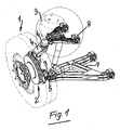
- the wheel 1 of a motor vehicle is supported by a per se known supporting assembly, generally indicated by the reference 2.
- the bottom end portion 3 and top end portion 4 of the supporting assembly are coupled, through an articulated spindle 5, respectively 6, to an arm bottom assembly 7 and an arm top assembly 8, which are connected to one another at the corresponding articulated V-shape spindle 5, 6.
- the top arm assembly 8 supports a resilient or elastic element 9 which can comprise, for example, an air cushion element, forming an air spring, on which spring the body (not shown) of the motor vehicle bears.
- a resilient or elastic element 9 which can comprise, for example, an air cushion element, forming an air spring, on which spring the body (not shown) of the motor vehicle bears.
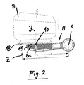
- the top arm is partially shown by a front view and partially by a cross-sectional view.
- the front end portion 8a of said arm 8 comprises a precisely arranged throughgoing hole 10.
- a clamping screw (not shown) for clamping the cushion element 9 being engageable in said throughgoing hole 10.
- the arm 8 has a rotary axis X, whereas the throughgoing hole 10 is formed through the front portion 8a of the arm 8 and has an axis Y, the letter Z showing a swinging axis.
- Figure 2 shows the distance A of the swinging axis Z to the rotary axis X.
- the letter B shows the distance between the axis Y and axis X of the hole 10 for receiving said clamping screw (not shown) for clamping said cushion element 9.
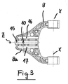
- Figure 3 further shows the arms 8 of the suspension assembly, said arm 8 being swingable about the axis X, and is moreover herein shown the rotary point Z thereof.
- the front portion 8a of the arms 8 comprises, according to the present invention, on the side thereof facing the cushion element 9, a central guide or sliding block 15, including the throughgoing hole 10.
- the central guide 15 in particular, adjoins a side guide 16 and a further side guide 17.
- Said base 18 is advantageously made as a flat plate.
- said double arm 8 will be made as a standard piece including said guides 15, 16 and 17, but without the hole.
- the arm 8 according to the present invention can be perforated only upon knowing its application depending on the type of the vehicle, it will be possible to use a standard suspension assembly.
Landscapes
- Engineering & Computer Science (AREA)
- Mechanical Engineering (AREA)
- Vehicle Body Suspensions (AREA)
- Motor Or Generator Frames (AREA)
Applications Claiming Priority (1)
| Application Number | Priority Date | Filing Date | Title |
|---|---|---|---|
| IT000698A ITMI20070698A1 (it) | 2007-04-04 | 2007-04-04 | Sospensione per la ruota di un autoveicolo in particolare di un autobus |
Publications (2)
| Publication Number | Publication Date |
|---|---|
| EP1977914A2 true EP1977914A2 (fr) | 2008-10-08 |
| EP1977914A3 EP1977914A3 (fr) | 2008-10-15 |
Family
ID=39535673
Family Applications (1)
| Application Number | Title | Priority Date | Filing Date |
|---|---|---|---|
| EP08004234A Withdrawn EP1977914A3 (fr) | 2007-04-04 | 2008-03-06 | Suspension pour roue d'un véhicule à moteur, en particulier un bus |
Country Status (4)
| Country | Link |
|---|---|
| US (1) | US20080258419A1 (fr) |
| EP (1) | EP1977914A3 (fr) |
| CN (1) | CN101279577A (fr) |
| IT (1) | ITMI20070698A1 (fr) |
Cited By (1)
| Publication number | Priority date | Publication date | Assignee | Title |
|---|---|---|---|---|
| ITMI20111529A1 (it) * | 2011-08-10 | 2013-02-11 | Ansaldo En Holding S P A | Gruppo assale per veicolo elettrico e veicolo elettrico comprendente detto gruppo assale |
Families Citing this family (4)
| Publication number | Priority date | Publication date | Assignee | Title |
|---|---|---|---|---|
| US7866681B1 (en) * | 2009-07-08 | 2011-01-11 | Arvinmeritor Technology, Llc | Self-guided air spring assembly |
| US10173705B2 (en) * | 2014-12-30 | 2019-01-08 | Tofco Industries, Inc. | Cart suspension system |
| US9987896B2 (en) * | 2016-04-22 | 2018-06-05 | Vantage Mobility International, Llc | Suspension systems, wheel spindle assemblies, and methods of retrofitting wheel spindles |
| CN110239301B (zh) * | 2019-06-20 | 2020-07-31 | 南京跃荣机械制造有限公司 | 一种一体造型的带阻尼吸能机构的冲压摆臂 |
Family Cites Families (9)
| Publication number | Priority date | Publication date | Assignee | Title |
|---|---|---|---|---|
| US2303545A (en) * | 1940-10-24 | 1942-12-01 | Jr Edward F Graham | Motor vehicle wheel suspension and shock absorption apparatus |
| US3178202A (en) * | 1961-12-04 | 1965-04-13 | Ford Motor Co | Vehicle wheel suspension |
| AT391110B (de) * | 1988-10-17 | 1990-08-27 | Graef & Stift | Radfuehrung fuer lenkbare und antriebsfaehige raeder von kraftfahrzeugen |
| DE4213676C2 (de) * | 1992-04-25 | 1996-02-22 | Continental Ag | Luftfeder für Fahrzeuge mit einem elastomeren Rollbalg und einem Abrollkolben |
| HU220550B1 (hu) * | 1996-03-01 | 2002-03-28 | The Goodyear Tire & Rubber Co. | Szerelt légrugó és eljárás annak rögzítésére |
| DE10011417B4 (de) * | 2000-03-09 | 2006-01-26 | Daimlerchrysler Ag | Einzelradaufhängung mit radführenden Schräglenkern |
| DE20022516U1 (de) * | 2000-09-07 | 2001-11-08 | Thyssen Krupp Automotive AG, 44793 Bochum | Radaufhängung |
| US7152866B2 (en) * | 2004-01-14 | 2006-12-26 | Watson & Chalin Manufacturing, Inc. | Steerable and liftable independent suspension system |
| DE102004058698B3 (de) * | 2004-12-06 | 2006-02-09 | Muhr Und Bender Kg | Radaufhängung mit Federverstellung für Kraftfahrzeuge |
-
2007
- 2007-04-04 IT IT000698A patent/ITMI20070698A1/it unknown
-
2008
- 2008-03-06 EP EP08004234A patent/EP1977914A3/fr not_active Withdrawn
- 2008-04-01 US US12/080,234 patent/US20080258419A1/en not_active Abandoned
- 2008-04-02 CN CNA2008100883837A patent/CN101279577A/zh active Pending
Cited By (2)
| Publication number | Priority date | Publication date | Assignee | Title |
|---|---|---|---|---|
| ITMI20111529A1 (it) * | 2011-08-10 | 2013-02-11 | Ansaldo En Holding S P A | Gruppo assale per veicolo elettrico e veicolo elettrico comprendente detto gruppo assale |
| WO2013021367A1 (fr) * | 2011-08-10 | 2013-02-14 | Ansaldo Energia S.P.A. | Ensemble essieu de véhicule électrique et véhicule électrique comprenant cet ensemble essieu |
Also Published As
| Publication number | Publication date |
|---|---|
| CN101279577A (zh) | 2008-10-08 |
| US20080258419A1 (en) | 2008-10-23 |
| EP1977914A3 (fr) | 2008-10-15 |
| ITMI20070698A1 (it) | 2008-10-05 |
Similar Documents
| Publication | Publication Date | Title |
|---|---|---|
| US7967310B2 (en) | Wheel suspension for the rear wheels of a motor vehicle | |
| EP1977914A2 (fr) | Suspension pour roue d'un véhicule à moteur, en particulier un bus | |
| US4616845A (en) | Toe adjustment apparatus | |
| US8814191B2 (en) | Leaf spring having a rigidly connected elastic connecting body for a motor vehicle | |
| EP2007598B1 (fr) | Bras pour une suspension indépendante de véhicule à moteur et suspension indépendante de véhicule à moteur comportant ce bras | |
| US10279640B2 (en) | Wheel suspension with centrally pivoted transverse leaf spring | |
| US9096111B2 (en) | Coupled torsion beam axle type suspension system | |
| JP2003515489A (ja) | 車両のリジッドアクスルのための車軸懸架装置 | |
| CN106142029B (zh) | 一种用于客车后桥装配的工装车 | |
| US10471789B2 (en) | Suspension device | |
| US20120242055A1 (en) | Bearing, vehicle, and method for assembling a vehicle | |
| CN113784855A (zh) | 板簧支承装置和具有这种板簧支承装置的机动车车轮悬架 | |
| CN204432831U (zh) | 车门铰链安装夹具 | |
| US20130147145A1 (en) | Structure of vehicle subframe | |
| KR100316893B1 (ko) | 차량용 토션 빔 타입 현가장치의 토션 빔 마운팅 구조 | |
| CN201023405Y (zh) | 一种汽车下控制臂总成 | |
| CN104986122A (zh) | 一种车载设备固定装置 | |
| CN210653431U (zh) | 天窗段差调整装置 | |
| US7699327B2 (en) | Wheel suspension | |
| US9254726B2 (en) | Transverse leaf spring bearing unit and transverse leaf spring arrangement for a motor vehicle | |
| CN102079299B (zh) | 车辆的停车制动系统 | |
| CN218211949U (zh) | 四分之一悬架多工位耐久试验台 | |
| CN102216095A (zh) | 用于车轮悬架的横向导臂 | |
| JP2010085215A (ja) | ストロークセンサ | |
| DE102005041045B4 (de) | Niveausensoranordnung für ein Kraftfahrzeug |
Legal Events
| Date | Code | Title | Description |
|---|---|---|---|
| PUAI | Public reference made under article 153(3) epc to a published international application that has entered the european phase |
Free format text: ORIGINAL CODE: 0009012 |
|
| PUAL | Search report despatched |
Free format text: ORIGINAL CODE: 0009013 |
|
| AK | Designated contracting states |
Kind code of ref document: A2 Designated state(s): AT BE BG CH CY CZ DE DK EE ES FI FR GB GR HR HU IE IS IT LI LT LU LV MC MT NL NO PL PT RO SE SI SK TR |
|
| AX | Request for extension of the european patent |
Extension state: AL BA MK RS |
|
| AK | Designated contracting states |
Kind code of ref document: A3 Designated state(s): AT BE BG CH CY CZ DE DK EE ES FI FR GB GR HR HU IE IS IT LI LT LU LV MC MT NL NO PL PT RO SE SI SK TR |
|
| AX | Request for extension of the european patent |
Extension state: AL BA MK RS |
|
| STAA | Information on the status of an ep patent application or granted ep patent |
Free format text: STATUS: THE APPLICATION HAS BEEN WITHDRAWN |
|
| 18W | Application withdrawn |
Effective date: 20081106 |