EP1978147B1 - Feste Endbearbeitungsvorrichtung für Jacken - Google Patents
Feste Endbearbeitungsvorrichtung für Jacken Download PDFInfo
- Publication number
- EP1978147B1 EP1978147B1 EP20070006948 EP07006948A EP1978147B1 EP 1978147 B1 EP1978147 B1 EP 1978147B1 EP 20070006948 EP20070006948 EP 20070006948 EP 07006948 A EP07006948 A EP 07006948A EP 1978147 B1 EP1978147 B1 EP 1978147B1
- Authority
- EP
- European Patent Office
- Prior art keywords
- jacket
- torso
- pressers
- skirts
- finishing device
- Prior art date
- Legal status (The legal status is an assumption and is not a legal conclusion. Google has not performed a legal analysis and makes no representation as to the accuracy of the status listed.)
- Not-in-force
Links
- 239000007787 solid Substances 0.000 title claims description 19
- 230000001174 ascending effect Effects 0.000 claims description 13
- 230000037303 wrinkles Effects 0.000 description 9
- 230000002093 peripheral effect Effects 0.000 description 7
- 210000000078 claw Anatomy 0.000 description 4
- 230000003287 optical effect Effects 0.000 description 4
- 210000000481 breast Anatomy 0.000 description 2
- 210000000038 chest Anatomy 0.000 description 2
- 230000000881 depressing effect Effects 0.000 description 2
- 210000003414 extremity Anatomy 0.000 description 2
- 235000000396 iron Nutrition 0.000 description 2
- 238000000034 method Methods 0.000 description 2
- 208000020401 Depressive disease Diseases 0.000 description 1
- 239000006185 dispersion Substances 0.000 description 1
- 238000001035 drying Methods 0.000 description 1
- 239000004744 fabric Substances 0.000 description 1
- 210000003127 knee Anatomy 0.000 description 1
- 239000002689 soil Substances 0.000 description 1
- 238000010025 steaming Methods 0.000 description 1
Images






Classifications
-
- D—TEXTILES; PAPER
- D06—TREATMENT OF TEXTILES OR THE LIKE; LAUNDERING; FLEXIBLE MATERIALS NOT OTHERWISE PROVIDED FOR
- D06F—LAUNDERING, DRYING, IRONING, PRESSING OR FOLDING TEXTILE ARTICLES
- D06F71/00—Apparatus for hot-pressing clothes, linen or other textile articles, i.e. wherein there is substantially no relative movement between pressing element and article while pressure is being applied to the article; Similar machines for cold-pressing clothes, linen or other textile articles
- D06F71/18—Apparatus for hot-pressing clothes, linen or other textile articles, i.e. wherein there is substantially no relative movement between pressing element and article while pressure is being applied to the article; Similar machines for cold-pressing clothes, linen or other textile articles specially adapted for pressing particular garments or parts thereof
- D06F71/20—Apparatus for hot-pressing clothes, linen or other textile articles, i.e. wherein there is substantially no relative movement between pressing element and article while pressure is being applied to the article; Similar machines for cold-pressing clothes, linen or other textile articles specially adapted for pressing particular garments or parts thereof for pressing shirts
-
- D—TEXTILES; PAPER
- D06—TREATMENT OF TEXTILES OR THE LIKE; LAUNDERING; FLEXIBLE MATERIALS NOT OTHERWISE PROVIDED FOR
- D06F—LAUNDERING, DRYING, IRONING, PRESSING OR FOLDING TEXTILE ARTICLES
- D06F71/00—Apparatus for hot-pressing clothes, linen or other textile articles, i.e. wherein there is substantially no relative movement between pressing element and article while pressure is being applied to the article; Similar machines for cold-pressing clothes, linen or other textile articles
- D06F71/32—Details
- D06F71/40—Holders or stretchers for the article to be pressed
Definitions
- This invention relates to a solid finishing device for jackets (a jacket, coat or the like) and more particularly a solid finishing device of a type comprising a torso imitating to the chest or breast part of a human body, and using either steam or hot air to remove some wrinkles under a state in which the clothing is put on the torso to perform a smooth finishing.
- the conventional device of this type is provided with a front presser and a rear presser moved forward or rearward to or away from the torso below the front part or rear part of the torso to press the front and rear skirts of a jacket put on the torso. Then, this device lifts up the torso a little after fixing the skirts of the jacket with a pair of front and rear skirt pressers and pulls the jacket in a vertical direction to remove the wrinkles at the front and rear bodices. Accordingly, the conventional device of this type has shown a problem that some torn wrinkles are generated at the clothing ranging from the skirt pressing position to the sides of the jacket because the front and rear skirts are fixed with the skirt pressers.
- the solid finishing device of this type is formed not to generate any such torn wrinkles as above because the torn wrinkles may apply bad influence to the finished state of a jacket.
- the conventional device of this type is required that the jacket is arranged at the most suitable height for finishing to press accurately the skirts of the jacket by the skirts presser, and to apply a tension.
- the switch of an air cylinder for ascending or descending the torso were pushed many times by foot or knee to control height of the torso.
- this prior art device showed a problem that an efficiency of a jacket finishing operation is reduced because height adjustment for a torso needs a troublesome work.
- EP-A-0 170 106 Further relevant prior art is disclosed in EP-A-0 170 106 .
- a technical concept of this invention is to provide a device capable of finishing in tension the skirts of a jacket put on a torso under a state in which not only the front and rear parts but also the sides are fixed.
- this invention is constituted as follows.
- this invention comprises a pair of front and rear skirt pressers for pressing the front and rear skirts of the jacket put on a torso and a pair of right and left side tension applicators for pushing wide both side skirts of the jacket put on the torso laterally, wherein the side pressers are provided with aforesaid side tension applicators for holding and pressing both side skirts of the jacket in cooperation with the side tension applicators.
- this invention has such a configuration as above, so that this invention can prevent some torn wrinkles from being generated on the jacket and finish the jacket neatly.
- this invention has some side pressers at the side tension applicators. Accordingly, in the case of this invention, it is not necessary for an exclusive location for fixing side pressers to be arranged below the torso. Due to this fact, in accordance with this arrangement, there are provided some merits that some pipes and accessories or the like can be arranged below the torso and a space below the torso can be effectively utilized.
- Application of this invention enables that the jacket is arranged at the most suitable height and further finishing operation enables the jacket to finished neatly.
- this invention is constituted such that the lower ends of the side tension applicators are provided with hook-like supporting members arranged to be suspended down with the horizontal portions being projected at sides of the torso, the side pressers are pivoted at the horizontal portions of the supporting members with a shaft extending in a forward or rearward direction, and arranged in such a way that they may be turned around the shaft and raised or lowered.
- a reason why the foregoing arrangement is preferable consists in the fact that a space occupying the sides for operating the side pressers can be reduced and correspondingly a size of the device can be made small and its occupying space can be made narrow.
- the torso comprises some collar pressers for use in pressing the lapels of a jacket.
- a reason why the foregoing arrangement is preferable consists in the fact that not only the front and rear bodices of the jacket but also the lapels can be finished neatly.
- a size of the collar presser is set such that the upper collar of the lapel can be usually pressed.
- the collar pressers are formed like a pair of right and left vanes imitating with a shape of butterfly and in such a way that they can be freely opened or closed around the inside pivot shaft by a predetermined angle in a forward or rearward direction of the torso.
- the inside pivot shaft is meant by a shaft arranged at the central part or a location near the central part so as to enable the opening or closing operation of the pair of right and left vane-like collar pressers. More practically, it can be realized by arranging one (one piece) collar presser or arranging a pair of right and left collar pressers at linear symmetrical positions.
- the predetermined angle is meant by an angle in which each of the right and left collar pressers is turned in an inward or outward direction around the front side pivot shaft of the torso to enable the lapels to be pressed.
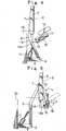
- reference numeral 1 denotes a torso imitating a chest part (a breast part) of a human body and reference numeral 2 denotes a jacket put on the torso 1.
- the torso 1 is formed in such a way that it can be freely ascended or descended through an extending or retracting action of a rod in a first air cylinder acting as the driving device 3.
- Reference numeral 4 denotes a pair of front and rear skirt pressers for use in pressing the front and rear skirts of the jacket 2.
- Reference numeral 5 denotes a pair of right and left side tension applicators for use in pushing wide both skirts of the jacket 2 put on the torso 1 in an outward direction to apply a tension to each of the sides of the skirt.
- the side tension applicators 5 are pivoted at the upper parts of raised frames 6 through the first lateral shafts 7 extending along the forward and rearward directions.
- the lower ends of the raised frames 6 are pivoted to the outer ends of the lateral-directed supporting frames 8 through the second lateral shafts 9 extending along the forward and rearward directions.
- the inner ends of the supporting frames 8 are fixed to the side surfaces of a rectangular-shaped base frame 10.
- each of the raised frames 6 is formed into a bent shape with the lower part inclined from the position of the second lateral shaft 9 to the base frame 10 and the vertical upper part communicated with the lower part.
- Reference numeral 11 denotes the second air cylinders installed in a slanted manner between the lower part of each of the raised frames 6 and each of the supporting frames 8 with their rods being inclined outward.
- the raised frames 6 are turned laterally around the second lateral shafts 9 to cause the skirt and side portions of the jacket 2 to be pushed wide laterally and apply a certain tension to them (refer to Figs. 3 to 5 ).
- heat-resistant cloths 12 are tensioned between each of receiving irons 4a of the skirt pressers 4 and the side tension applicators 5 with a margin in such a way that a motion of the side tension applicators 5 may not be restricted and are formed for not to dispel steam and hot air supplied into the inside portion of the jacket 2.
- Reference numeral 13 denotes side pressers cooperating with the side tension applicators 5 to hold the side skirts of the jacket 2 and press them.
- the side pressers 13 are installed at the side tension applicators 5.
- Reference numeral 14 denotes a hook-shaped supporting member.
- the supporting member 14 is formed such that its horizontal portion 14a is projected at the side part of the torso 1 below the lower end of the side tension applicator 5 and arranged in a suspended state.
- the side presser 13 is pivoted at the horizontal part 14a of the supporting member 14 with the shaft 15 extending in a forward or rearward direction and arranged in such a way that it may be turned around the shaft 15 so as to be freely raised or lowered.
- Reference numeral 16 denotes a third air cylinder for raising or lowering the side presser 13.
- the third air cylinder 16 is pivoted between the horizontal part 14a of the supporting member 14 and a projecting part 17 at the rear surface side of the side presser 13 so as to cause the rod to become in parallel with the front surface (the pressing surface) of the side presser 13, and the third air cylinder 16 is also formed to be raised or lowered together with the side presser 13 when the rod of the third air cylinder 16 is extended or retracted.
- reference numeral 18 denotes a collar presser for use in pressing a lapel 2a of the jacket 2.
- the collar pressers 18 are formed as a pair of right and left vanes similar to a shape of butterfly and further formed in such a way that they can be opened or closed by a predetermined angle in a forward or rearward direction of the torso 1 around the inner pivoted shaft 19 (refer to Figs. 9 and 10 or the like).
- a pair of right and left pivoted shafts 19 are arranged as seen from their top plan view at an upper plate 21 and a lower plate 22 fixed inside a fixing part 20 projected like a hook-like handle from a neck part 1a of the torso 1 (refer to Fig. 8 ) to the forward direction in this preffered embodiment.
- Arm pieces 23 for supporting collar pressers 18 are pivoted with the pivot shafts 19 to the upper plate 21 and the lower plate 22 at their inner ends.
- the collar pressers 18 are arranged at the outer ends of the arm pieces 23 in such a way that their pressing forces may be adjusted by adjusting resiliency of coil springs 25 with knobs 24.
- Reference numeral 26 denotes a lever for use in opening or closing the collar pressers 18 by a predetermined angle.
- the outer end of this lever 26 is provided with a spherical knob 26a, and its inner end is connected to a hook-like extended plate 27 as seen from its top plan view.
- This extended plated 27 is pivoted to the upper plate 21 through a vertical shaft 28, slightly spaced apart from the upper plate 21 and arranged over it in parallel with the upper plate 21.
- an inner corner at the extremity end of the extended plate 27 is cut into a concave curved shape and formed at a recess part 27a.
- Reference numeral 21a denotes a guide hole that is formed as an arcuate shape as seen from its top plan view.
- a shaft rod 29 is passed through the guide hole 21a and a rotor 30 is fixed to the upper end of the shaft rod 29.
- the inner peripheral edge 27b of the extended plate 27 is formed to be engaged with the outer peripheral surface of the rotor 30.
- the recess part 27a is extended from the inner peripheral edge 27b, engaged with the rotor 30 to receive the rotor 30.
- the shaft rod 29 is always towed against the side of the torso 1 by a tension spring 31.
- Reference numeral 32 denotes a spring fixing member connected to the shaft rod 29.
- the tension spring 31 is applied between the upper end of the spring fixing member 32 and a pin 33 fixed to the inner side upper surface of a fixing part 20.
- the inner end of one arm piece 23 (the right arm piece 23 in Fig. 1 of this preferred embodiment) is extended up to a position of the shaft rod 29 and connected integral with the shaft rod 29.
- a lower location 23a (refer to Fig. 9 or the like) at the inner end of the other arm piece 23 (the left arm piece 23 in Fig. 1 ) is extended up to a position of the shaft rod 29 and at the same time it is formed to have a recess 34 having a U-shaped section as seen in its top plan view. Then, the other arm piece 23 is formed to be cooperated with the shaft rod 29 while the recess 34 is being engaged with the outer peripheral surface of the lower rotor 35 at the lower end of the shaft rod 29.
- reference numeral 36 denotes a lower part presser for use in pressing the lower part of the lapel 2a.
- This lower presser 36 is installed at the lower end of the rod member 37.
- the upper part of the rod member 37 is pivoted to the fixing part 20 through a third lateral shaft 38 extending along the right and left directions of the torso 1.
- the lower presser 36 is formed to be turned around the third lateral shaft 38 by a predetermined angle in a forward or rearward direction of the torso 1.
- the rod member 37 is hauled upward with the coil spring 39 and when an operator turns the lower presser 36 toward the torso 1 against the retracting force of this coil spring 39 and against the lower part of the lapel 2a, the rod member 37 is formed to cause its upper end to be engaged with a claw 40a of an engaging hook 40.
- the claw 40a of the engaging hook 40 is formed to be disengaged from the upper end of the rod member 37 by depressing the extremity end of an operating piece 41 projected from the front surface of the fixing part 20. Then, when the claw 40a is disengaged from the upper end of the rod member 37, the lower presser 36 is turned around the third lateral shaft 38 to the front part of the torso 1 with the recovering force of the soil spring 39 and pulled away. Further, reference numeral 42 denotes an operating knob for the lower presser 36.
- the operator puts the jacket 2 on the torso 1 while adjusting the positions of its shoulders and subsequently treads on a lifting pedal for the torso 1, for example. Then, the rod of the first air cylinder 3 extends to cause the jacket 2 to be lifted up together with the torso 1.
- a skirt sensor (not shown) arranged at a proper location detects a passage of the skirt, for example, after elapsing a predetermined time, driving of the first air cylinder 3 is stopped, and with this arrangement, the jacket 2 is arranged at the most suitable height.
- the operator under this state fixes the lapel 2a with the collar presser 18. More practically, the operator in Fig. 10 turns the lever 26 in a counter-clockwise direction (in an arrow direction) against a retraction force of the tension spring 31. Then, the extended plate 27 is turned around the vertical shaft 28 in the same direction as that of the former, so that the rotor 30 engaged with the inner peripheral edge 27b is gradually moved downward in this figure while being pushed with the inner peripheral edge 27b.
- the rotor 30 is made integral with the shaft rod 29, and the shaft rod 29 and one arm piece 23 (the right arm piece 23 in this figure) are connected to each other.
- the recess 27a of the extended plate 27 is engaged with the rotor 30 as shown in Fig. 11 .
- the right collar presser 18 presses against the right lapel 2a.
- the left arm piece 23 is engaged with the lower rotor 35 where the recess 34 at the lower location 23a is made integral with the shaft rod 29. Accordingly, when the operator turns the lever 26 in a counter-clockwise direction as seen in Fig. 10 , the left arm piece 23 is turned around the left pivot shaft 19 in a clockwise direction as the shaft rod 29 is moved toward a direction where it is moved away from the torso 1 (in the downward direction in this figure).
- the left collar presser 18 presses against the left lapel 2a.
- the right and left collar pressers 18 simultaneously press against the right and left lapels 2a in this manner.
- the operator operates the lever 26 in a manner opposite to the aforesaid example. That is, the operator draws the lever 26 and turns the lever 26 in a clockwise direction as seen in Fig. 11 . Then, the engaged state between the rotor 30 and the recess 27a is released and subsequently the rotor 30 is moved gradually toward the torso 1 (in an upward direction in this figure) with the recovering force of the tension spring 31 while being contacted with the inner peripheral edge 27b of the extended plate 27.
- the operator depresses an automatic start button, for example.
- the collar presser 4 fixes the forward and rearward skirts of the jacket 2 in an order of a rear side and front side, subsequently the right and left side tension applicators 5 are moved simultaneously to the sides to push wide both skirts of the jacket 2 and apply a tension to them.
- the side pressers 13 press both side skirts against the side tension applicators 5 simultaneously and fix them.
- the first air cylinder 3 (refer to Fig. 2 ), for example, is operated to cause its rod to be slightly lifted up to lift up the torso 1 and the jacket 2 is pulled and tensioned in a vertical direction. Then, both steam and hot air are blown against inside portion of the jacket 2 to steam the jacket 2 to extend its wrinkles and dry finish it.
- the rod of the first air cylinder 3 is retracted and the torso 1 descends and returns to its set position.
- the rods in the second air cylinder 11 and the third air cylinder 16 are retracted and the side tension applicators 5 are returned inwardly and at the same time the side pressers 13 are turned outwardly to release the depressed states of both skirts, and subsequently the pair of front and rear skirt pressers 4 are recovered to release the fixed state of the skirts.
- the operator operates the lever 26 (refer to Fig. 1 ) in an opposite manner to that described above, depresses down the operating piece 41 (refer to Fig. 8 ) so as to recover the collar pressers 18 and the lower part presser 36. Then, the operator puts off the jacket 2 from the torso 1 and completes the finishing operation.
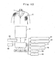
- reference numeral 1 denotes a torso and reference numeral 2 denotes a jacket put on the torso.
- the torso 1 is formed to be freely ascendable or descendable with the first air cylinder acting as a driving device 3 in this preferred embodiment.
- Reference numeral 50 denotes a detector for outputting a signal while a skirt of the jacket 2 passes through it.
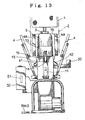
- This detector 50 in this preferred embodiment is constituted by an optical sensor and as shown in Fig.13 , the detector 50 is installed at the rear lower side of the torso 1.
- This detector 50 outputs a signal when the jacket 2 ascends together with the torso 1 and the skirt passes through an optical path.
- Reference numeral 51 denotes a control unit for receiving an output signal from the detector 50 and stopping an ascending action of a rod of the first air cylinder acting as a driving device 3.
- This control unit 51 in this preferred embodiment is constituted by a micro-computer and stored in a control panel 52 (refer to Fig.13 and Fig.14 ) placed at the front lower part of the torso 1.
- a control panel 52 (refer to Fig.13 and Fig.14 ) placed at the front lower part of the torso 1.
- To the input ports of the control unit 51 are electrically connected an auto-start button (SW1), an ascending pedal (SW2) for the torso 1, a finish button (SW3) and a timer setting unit 53 and the like in addition to the aforesaid detector 50.
- SW1 auto-start button
- SW2 ascending pedal
- SW3 finish button
- the control unit In addition, to the output ports of the control unit are electrically connected the first air cylinder acting as the driving device 3, a steam generating device 54 for steaming the jacket 2 put on the torso 1, a hot air generating device 55 for drying and finishing the jacket 2 and various types of air cylinder to be described later.
- the device of the present invention is constructed such that a pair of front and rear skirt pressers 4 for use in pressing the front and rear skirts of the jacket 2 at the front side and the rear side of the torso 1.
- Reference numeral 41 denotes a front side skirt pressing air cylinder
- reference numeral 42 denotes a rear side skirt presser air cylinder.
- the device of the present invention in accordance with this preferred embodiment is formed to be provided with a pair of right and left side tension applicators 5 for use in pushing wide both side skirts of the jacket 2 put on the torso 1, and side pressers 13 for use in pushing wide both skirts of the jacket 2 put on the torso 1 outward and applying tension to them.
- the side tension applicators 5 move forward and rearward in response to an extending or retracting operation of the rod in the second air cylinder 11 for applying side tensions.
- Reference numeral 14 denotes a hook-shaped supporting member as seen in its front elevational view. This supporting member 14 is arranged at the lower end of each of the side tension applicators 5 in a suspended manner. Then, the side pressers 13 are arranged at the horizontal part 14a of the supporting member 14 through a shaft 15 (refer to Fig.13 ) in such a manner as they are raised or lowered.
- Reference numeral 16 denotes the third air cylinder for raising or lowering the side pressers 13.
- a heat-resistant cloth 19 is tensioned among the receiving irons 4a of a pair of front and rear skirt pressers 4 and the side tension applicators 5 with a surplus state so as not to apply any restriction against motion toward the side tension applicators.
- the jacket 2 there are a short jacket such as a suit and a jacket and a longer one such as a coat and the like.
- the short jacket 2 shows an advantage that the center of the jacket 2 is relatively hardly displaced from the center of the torso 1 when the jacket is arranged at the position where it is most suitable for finishing work. Accordingly, in this case, approximate all the steps can be carried out automatically by depressing the auto-start button (SW1) after the jacket 2 is put on the torso 1 as shown in Fig.16 .
- SW1 auto-start button
- SW1 auto-start button
- the control unit 51 receives this signal and upon elapsing of set time (for example, 2 seconds) preset at a timer setting unit 53, the control unit 50 closes the solenoid valve to cause an ascending action of the rod in the first cylinder acting as the driving device 3 to be stopped.
- set time for example, 2 seconds
- the control unit 50 closes the solenoid valve to cause an ascending action of the rod in the first cylinder acting as the driving device 3 to be stopped.
- the device of the present invention drives, under this state, the rear side skirt presser air cylinder 42 (refer to Fig.13 ) and the front side skirt presser air cylinder 41 (refer to Fig.13 ).
- the front and rear skirts of the jacket 2 are fixed by the skirt pressers 4 in an order of the front side and rear side.
- the side tension air cylinder 11 is driven to cause the side tension applicators 5 to move side and both skirts of the jacket 2 are pushed wide, thereafter the side presser air cylinder 16 is driven.
- the side pressers 13 push both skirts against the side tension applicators 5 and fix them.
- the jacket 2 is steamed with steam supplied from the steam generating device 54 and the rod in the first air cylinder acting as the driving device 3 slightly ascends to cause the jacket to be extended in a vertical direction and some wrinkles there are removed.
- hot air from the hot air generating device 55 is blown into the jacket 2 so as to dry finish it (refer to Fig.16C ).
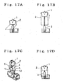
- the worker puts the jacket 2 on the torso 1 in the same manner as that described above and applies a tension against the shoulders of the jacket 2 (refer to Fig.17A ).
- the worker treads on the ascending pedal (SW2) for the torso 1.
- the rod in the first air cylinder acting as the driving device 3 extends in the same manner as described above and the torso 1 ascends.
- the detector 50 detects the skirts of the jacket 2 ascending together with the torso 1, the detector may output a signal to the control unit 51.
- the control unit 51 receives this signal and when a set time elapses, the ascending of the rod in the first air cylinder is stopped.
- the jacket 2 is arranged at the most appropriate finishing height (refer to Fig.17B ).
- the worker manually aligns the center of the jacket 2 with the center of the torso 1.
- the worker depresses the auto-start button (SW1).
- the skirts of the jacket 2 are fixed in the same manner as described above in the order of front side and rear side, both sides of the jacket 2 are tensioned by the side tension applicators 5 toward sides and at the same time both skirts are fixed with the side presser applicators 13.
- the jacket 2 is steamed with steam, the torso 1 slightly ascends, the jacket 2 is pulled in a vertical direction to extend some wrinkles and dry finished with steam (refer to Fig.17C ).
- the worker depresses the finish button (SW3). With this operation, the torso 1 descends and the jacket 2 returns back to its set position (refer to Fig.17D ). The worker takes off the jacket 2 from the torso 1 under this state and removes it.
Landscapes
- Engineering & Computer Science (AREA)
- Textile Engineering (AREA)
- Treatment Of Fiber Materials (AREA)
Claims (5)
- Feste Endbearbeitungsvorrichtung für Jacken (2), die ein Paar aus vorderen und hinteren Schoßpressen (4) zum Pressen der vorderen und hinteren Schöße der Jacke (2), die auf einem Torso (1) angebracht ist, umfasst,
gekennzeichnet durch
ein Paar aus rechten und linken Seitenspannungsapplikatoren (5) zum Weitdrücken beider Seitenschöße der Jacke (2), die auf dem Torso (1) angebracht ist, in Querrichtung, wobei die Seitenspannungsapplikatoren (5) mit Seitenpressen (13) zum Halten und Pressen beider Seitenschöße der Jacke (2) in Zusammenwirkung mit den Seitenspannungsapplikatoren (5) versehen sind. - Feste Endbearbeitungsvorrichtung für Jacken nach Anspruch 1, weiter umfassend:eine Antriebsvorrichtung (3) zum Ansteigen oder Absinken des Torsos (1);einen Detektor (50) zum Abgeben eines Signals durch Hindurchgehen von Schößen der Jacke (2), die zusammen mit dem Torso (1) ansteigt; undeine Steuereinheit (21) zum Empfangen eines Ausgangssignals vom Detektor (50) und Stoppen des Ansteigens der Antriebsvorrichtung (3).
- Feste Endbearbeitungsvorrichtung für Jacken nach Anspruch 1 oder 2, wobei die unteren Enden der Seitenspannungsapplikatoren (5) mit hakenähnlichen Stützteilen (14) versehen sind, die so angeordnet sind, dass sie nach unten abstehen, wobei die horizontalen Abschnitte (14a) an Seiten des Torsos (1) vorstehen, die Seitenpressen (13) an den horizontalen Abschnitten (14a) der Stützteile (14) mit einer Achse (15) angelenkt sind, die sich in einer Vorwärts- oder Rückwärtsrichtung erstreckt, und so angeordnet sind, dass sie um die Achse (15) herum gedreht und angehoben oder abgesenkt werden können.
- Feste Endbearbeitungsvorrichtung für Jacken nach den Ansprüchen 1 bis 3, wobei Kragenpressen (18) zum Pressen von Revers (2a) der Jacke (2) vorgesehen sind.
- Feste Endbearbeitungsvorrichtung für Jacken nach Anspruch 4, wobei die Kragenpressen (18) als ein Paar aus rechten und linken Flügeln ausgebildet sind, die die Form eines Schmetterlings imitieren, und derart, dass sie um die innere Gelenkachse (19) um einen vorbestimmten Winkel in einer Vorwärts- und Rückwärtsrichtung des Torsos (1) frei geöffnet oder geschlossen werden können.
Priority Applications (2)
| Application Number | Priority Date | Filing Date | Title |
|---|---|---|---|
| EP20070006948 EP1978147B1 (de) | 2007-04-03 | 2007-04-03 | Feste Endbearbeitungsvorrichtung für Jacken |
| DE200760006420 DE602007006420D1 (de) | 2007-04-03 | 2007-04-03 | Feste Endbearbeitungsvorrichtung für Jacken |
Applications Claiming Priority (1)
| Application Number | Priority Date | Filing Date | Title |
|---|---|---|---|
| EP20070006948 EP1978147B1 (de) | 2007-04-03 | 2007-04-03 | Feste Endbearbeitungsvorrichtung für Jacken |
Publications (2)
| Publication Number | Publication Date |
|---|---|
| EP1978147A1 EP1978147A1 (de) | 2008-10-08 |
| EP1978147B1 true EP1978147B1 (de) | 2010-05-12 |
Family
ID=38470338
Family Applications (1)
| Application Number | Title | Priority Date | Filing Date |
|---|---|---|---|
| EP20070006948 Not-in-force EP1978147B1 (de) | 2007-04-03 | 2007-04-03 | Feste Endbearbeitungsvorrichtung für Jacken |
Country Status (2)
| Country | Link |
|---|---|
| EP (1) | EP1978147B1 (de) |
| DE (1) | DE602007006420D1 (de) |
Family Cites Families (5)
| Publication number | Priority date | Publication date | Assignee | Title |
|---|---|---|---|---|
| GB618769A (en) * | 1945-10-19 | 1949-02-28 | Forrest John Couch | Improvements in and relating to pressing machines for shirts and like garments |
| JPS6133700A (ja) * | 1984-07-17 | 1986-02-17 | 有限会社 三幸社 | プレス仕上げ機 |
| IT1292062B1 (it) * | 1997-06-03 | 1999-01-25 | Rotondi Group S R L | Macchina stiratrice industriale dotata di un perfezionato sistema di movimento verticale della pressa superiore e di un dispositivo |
| DE10120657B4 (de) * | 2001-04-27 | 2005-12-08 | Veit Gmbh & Co | Sakkofinisher |
| US6868996B1 (en) * | 2003-07-01 | 2005-03-22 | San Kousha Co., Ltd | Body tension apparatus for shirts press machine |
-
2007
- 2007-04-03 EP EP20070006948 patent/EP1978147B1/de not_active Not-in-force
- 2007-04-03 DE DE200760006420 patent/DE602007006420D1/de active Active
Also Published As
| Publication number | Publication date |
|---|---|
| DE602007006420D1 (de) | 2010-06-24 |
| EP1978147A1 (de) | 2008-10-08 |
Similar Documents
| Publication | Publication Date | Title |
|---|---|---|
| US7370778B1 (en) | Solid finishing device for jackets | |
| US4057179A (en) | Garment pressing machines | |
| US4202190A (en) | Apparatus for hide stretching | |
| US3835559A (en) | Machine for ironing trousers | |
| EP1978147B1 (de) | Feste Endbearbeitungsvorrichtung für Jacken | |
| US3578790A (en) | Cabinet pants press | |
| US2875929A (en) | Shirt pressing machine | |
| US2723785A (en) | Machine for topping trousers | |
| JP4368347B2 (ja) | 上着の立体仕上げ装置 | |
| JP2002191900A (ja) | 生地の整形仕上げ方法および装置 | |
| US7438205B2 (en) | Shirt finishing machine | |
| CN101245545B (zh) | 衬衫整烫机 | |
| EP1978148B1 (de) | Hemdendbearbeitungsmaschine | |
| US5181333A (en) | Height adjustable pants presser with top finishing | |
| KR100466755B1 (ko) | 바지 마무리 장치 | |
| US2958967A (en) | Pressing machine | |
| JPH0637838Y2 (ja) | 衣類の袖プレス機 | |
| JP2002210298A (ja) | ズボン仕上げ機 | |
| JP2007117323A (ja) | 上着の裾検出機能付き立体仕上げ装置 | |
| KR100826035B1 (ko) | 겉옷의 입체 마무리 장치 | |
| JP4409522B2 (ja) | シャツ仕上げ機 | |
| JPH02193699A (ja) | シャツ仕上げ機 | |
| JPH0316639Y2 (de) | ||
| KR20090024348A (ko) | 셔츠 측부의 긴장법 및 이러한 방법에 사용되는 몸통부텐션장치 | |
| JPH11347300A (ja) | 衣類仕上げ機 |
Legal Events
| Date | Code | Title | Description |
|---|---|---|---|
| PUAI | Public reference made under article 153(3) epc to a published international application that has entered the european phase |
Free format text: ORIGINAL CODE: 0009012 |
|
| 17P | Request for examination filed |
Effective date: 20070403 |
|
| AK | Designated contracting states |
Kind code of ref document: A1 Designated state(s): AT BE BG CH CY CZ DE DK EE ES FI FR GB GR HU IE IS IT LI LT LU LV MC MT NL PL PT RO SE SI SK TR |
|
| AX | Request for extension of the european patent |
Extension state: AL BA HR MK RS |
|
| 17Q | First examination report despatched |
Effective date: 20081120 |
|
| AKX | Designation fees paid |
Designated state(s): DE FR GB IT |
|
| GRAP | Despatch of communication of intention to grant a patent |
Free format text: ORIGINAL CODE: EPIDOSNIGR1 |
|
| GRAS | Grant fee paid |
Free format text: ORIGINAL CODE: EPIDOSNIGR3 |
|
| GRAA | (expected) grant |
Free format text: ORIGINAL CODE: 0009210 |
|
| AK | Designated contracting states |
Kind code of ref document: B1 Designated state(s): DE FR GB IT |
|
| REG | Reference to a national code |
Ref country code: GB Ref legal event code: FG4D |
|
| REF | Corresponds to: |
Ref document number: 602007006420 Country of ref document: DE Date of ref document: 20100624 Kind code of ref document: P |
|
| PLBE | No opposition filed within time limit |
Free format text: ORIGINAL CODE: 0009261 |
|
| STAA | Information on the status of an ep patent application or granted ep patent |
Free format text: STATUS: NO OPPOSITION FILED WITHIN TIME LIMIT |
|
| PG25 | Lapsed in a contracting state [announced via postgrant information from national office to epo] |
Ref country code: IT Free format text: LAPSE BECAUSE OF FAILURE TO SUBMIT A TRANSLATION OF THE DESCRIPTION OR TO PAY THE FEE WITHIN THE PRESCRIBED TIME-LIMIT Effective date: 20100512 |
|
| 26N | No opposition filed |
Effective date: 20110215 |
|
| REG | Reference to a national code |
Ref country code: DE Ref legal event code: R097 Ref document number: 602007006420 Country of ref document: DE Effective date: 20110214 |
|
| GBPC | Gb: european patent ceased through non-payment of renewal fee |
Effective date: 20110403 |
|
| REG | Reference to a national code |
Ref country code: FR Ref legal event code: ST Effective date: 20111230 |
|
| PG25 | Lapsed in a contracting state [announced via postgrant information from national office to epo] |
Ref country code: FR Free format text: LAPSE BECAUSE OF NON-PAYMENT OF DUE FEES Effective date: 20110502 |
|
| PG25 | Lapsed in a contracting state [announced via postgrant information from national office to epo] |
Ref country code: GB Free format text: LAPSE BECAUSE OF NON-PAYMENT OF DUE FEES Effective date: 20110403 |
|
| PGFP | Annual fee paid to national office [announced via postgrant information from national office to epo] |
Ref country code: DE Payment date: 20200325 Year of fee payment: 14 |
|
| REG | Reference to a national code |
Ref country code: DE Ref legal event code: R119 Ref document number: 602007006420 Country of ref document: DE |
|
| PG25 | Lapsed in a contracting state [announced via postgrant information from national office to epo] |
Ref country code: DE Free format text: LAPSE BECAUSE OF NON-PAYMENT OF DUE FEES Effective date: 20211103 |