EP1978164A1 - Procédé destiné au dimensionnement et à la planification de systèmes de répartition d'eau froide - Google Patents
Procédé destiné au dimensionnement et à la planification de systèmes de répartition d'eau froide Download PDFInfo
- Publication number
- EP1978164A1 EP1978164A1 EP07111691A EP07111691A EP1978164A1 EP 1978164 A1 EP1978164 A1 EP 1978164A1 EP 07111691 A EP07111691 A EP 07111691A EP 07111691 A EP07111691 A EP 07111691A EP 1978164 A1 EP1978164 A1 EP 1978164A1
- Authority
- EP
- European Patent Office
- Prior art keywords
- flow rate
- regulator
- consumption
- water flow
- coding
- Prior art date
- Legal status (The legal status is an assumption and is not a legal conclusion. Google has not performed a legal analysis and makes no representation as to the accuracy of the status listed.)
- Withdrawn
Links
Images



Classifications
-
- E—FIXED CONSTRUCTIONS
- E03—WATER SUPPLY; SEWERAGE
- E03B—INSTALLATIONS OR METHODS FOR OBTAINING, COLLECTING, OR DISTRIBUTING WATER
- E03B7/00—Water main or service pipe systems
- E03B7/04—Domestic or like local pipe systems
Definitions
- the invention relates to a method for dimensioning and planning of fresh water distribution systems in buildings with a plurality of consumers and a pressure-independent flow regulator or volume-controlled jet regulator for use in such a method.
- the local flow regulator has a control core insert, comprising a support ring and a control core connected to webs.
- U- rectangular or semi-circular grooves are recessed, between which lie substantially flat lateral surfaces.
- An O-ring can then come in line, but also over a large area with the mantle surfaces in contact.
- the for the fluid medium, especially water, open cross-sections in the grooves and thus the flow rate is precisely defined and reproducible.
- jet regulators or jet shapers which are offered by Neoperl GmbH under the brand name "Neoperl®” or “Perlator®", are state of the art.
- Such jet regulators or jet shapers may have an integrated flow regulator whose operating principle is based on the fact that an elastically deformable element more or less closes or releases a passage gap for the fluid medium, depending on the prevailing pressure conditions.
- the corresponding sanitary installation device has for this purpose a continuous coding, which contains information on the installed parts. Furthermore, a recording device is provided with which the coding is readable.
- the pipe sections, rods or fittings used are preferably already provided in the production with a continuous coding according to the teaching there, which contains, for example, the nature of the pipe section or the connecting rod and which is arranged at fixed intervals.
- the coding is attached, for example, only on elongated connection points, ie on the pipe sections or connecting rods.
- the fittings are identified indirectly via the pipe sections or connecting rods.
- On the necessary recorder then only the type of connection part, so for example a plastic fitting, must be entered.
- a bill of material is then created, which, coupled with a product database, enables the exact billing of the installed sanitary pipe system.
- the coding according to EP 1 308 563 A2 preferably consists of a bar code, which can be identified with an optical reader and which is printed, for example, on the outside of the coded parts. Also, the coding can be spiraling on the coded parts be applied to create a reading opportunity in any position. However, the barcode or barcode can only be identified with a special reader, but not by simple inspection, and the information content hidden in the code can be recognized.
- Essential to the invention is also the use of pressure-independent quantity regulators or jet regulators, which have such a flow regulator, according to the teaching Claim 8.
- a basic idea of the invention lies in the fact that in the planning and execution of sanitary facilities basically only sanitary components are to be used at the consumption points, which have separate or integrated flow regulator. With stringent pursuit of this basic idea, the dimensioning of complex building installations for fresh water distribution systems is simpler, since the pressure fluctuations which usually arise during operation and can not be influenced can largely be disregarded.
- volume regulators are used on all significant sanitary components, it is also possible to control mixed pressure systems hot / cold or kitchen / bathroom. Ultimately, it is possible with the invention, essential prerequisites to save water and energy and thus to ensure CO 2 reduction.
- Each tapping point of the fresh water distribution system has a defined water flow or a fixed volume due to the pressure-independent volume regulator.
- the dimensioning can be made as needed, taking into account the particular application, e.g. shower or bath, kitchen, bidet or washbasin. In terms of volume, the dimensioning can be e.g. to the filling of a cistern, a washing machine or dishwasher dish.
- the product identification certificate contains information on the water flow rate or the water flow rate range in the form of an encoding, in particular a color coding.
- This color coding can about it Be used as a synonym for energy efficiency, for example, the color green for a desired and desired consumption reduction, ie, a lower flow rate, for example, for use in a hand basin.
- the number and type of future consumption points is determined in dimensioning and planning of fresh water distribution systems in buildings with a large number of consumers in a first step.
- a fixed volume e.g. Washing machine or cistern
- a defined water flow rate e.g. a shower is.
- Each water flow rate or each water flow rate range is assigned a coding, in particular a color coding, which is unique.
- At least information about a desired flow rate of the respective quantity regulator and the installation dimensions for the advantageous field of application can be taken from the product identification certificate.
- the outlets which are used in domestic installations, added to a pack information or it has such an indication, which indicates an optimal interaction with a pressure-independent flow regulator, preferably for this also a color coding is used, which corresponds to the water flow rate coding, so that the correct, preferred combination flow regulator / outlet fitting results solely from the assignment color to color.
- a classification can be made on the basis of the achieved efficiency classes. This classification, in turn, is preferably taken into account in the consumption fee determination. Likewise, the efficiency class of the fresh water distribution system can be used with legally required house energy pass.
- Efficiency class is to be understood as a classification or assessment which is not limited to the water and thus the indirect Energy consumption oriented, but also the noise, due to the flowing medium includes.
- the respective efficiency class also provides an indication of the extent to which CO 2 emissions can be reduced if the production of hot water is based on the use of fossil fuels.
- the sanitary component proposed for use in the implementation of the method according to the invention is a quantity regulator or a volume-controlled jet regulator.
- the jet regulator or jet former for fluid media consists of property-determining components which are sandwiched in the flow direction. These comprise at least one attachment screen, a Zerlegerplattenan extract and a sleeve body extending over its cross-sectional area, beam-forming, perforations having segments, to achieve adaptability to a variety of user and application requirements, the property-determining components are interchangeable and combinable and this on or in the sleeve body fastener and arranged on the Zerlegerplattenan angel corresponding fasteners, preferably molded or molded.
- the Zerlegerplattenan Aunt has at least on the outside a flow class specifying and the sleeve body a the flow type, namely laminar or air enriched, specifying optical encoding.
- the front screen is preferably designed to be translucent or preferably transparent.
- the flow regulator itself may have a further optical coding.
- optical codings are designed as different color codings.
- the color gradations or color differences of the respective codings can include color temperatures which can be visually detected by means of optoelectronic image acquisition and evaluation as well as without aids.
- the flow regulator has the control gap mentioned in the introduction, the flow cross-section of which is variable by means of an elastically deformable under the pressure of the fluid flowing medium element, in particular ring, wherein the transparent or translucent properties of the attachment screen are selected so that the flow regulator itself and the position of the deformable ring or the elastic element can be seen ,
- the elastic element or the elastic ring itself have an optical coding, in particular a color coding, which is in color contrast to the control gap or its bypass.
- the use of sanitary components designed in this way takes place on the basis of a code table authorized by the manufacturer, which indicates which optical coding of the components recognizable without dismantling corresponds to the respective application with respect to jet shape, flow rate limitation and / or flow class or approaches this application to a large extent.
- Fig. 1 a flow chart of the sizing and planning process
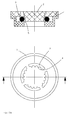
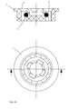
- Fig. 2a and 2 B Sectional views and top views of known flow regulator, wherein Fig. 2a the Regulierprofil is provided inside the elastic ring and after Fig. 2b an external regulation profile is present;
- Fig. 3 a sectional view of a typical volume-controlled jet regulator with representation of attachment screen, Zerlegerplattenan extract and sleeve body and
- Fig. 4 a typical representation of the flow behavior when using a flow regulator or a jet regulator with integrated flow regulator.
- Fig. 1 As in the schedule after Fig. 1 is represented in the, also automatically running, method of sizing and planning according to the invention, it is assumed to first determine or set the number and type of consumption points. After that, it is defined whether the respective consumption point is a filling of a fixed volume or a point of consumption with a defined water flow rate.
- the planning determines which defined water flow rate is intended for the respective consumption point, and a planning note is made for each of these consumption points by specifying the application together with the associated flow rate.
- the planning then further determines the use of pressure-dependent flow controllers and / or quantity-controlled jet regulators based on a present for these flow regulator and jet regulator product identification certificate at least for each of the consumption points with a defined water flow rate or each Wasser knockmannen Kunststoff, with a coding, especially color coding is assigned.
- the pressure-independent flow rate regulators used in accordance with according to the illustration Fig. 2a and 2 B assume a sleeve-shaped basic body 1.
- a centric insert body 2 has according to Fig. 2a an oriented on its side facing an elastomeric ring 3 side Regulierprofil 4 in the sense of a toothing.
- a pressure-dependent change in the position of the elastomeric ring 3 changes the cross section of the passage gap 5 for the fluid medium with the result that the flow rate can be kept almost constant even with pressure fluctuations above a certain minimum pressure.
- the operating principle of the flow regulator according to Fig. 2b is basically analogous to that as in the Fig. 2a shown, with the difference that an internal toothing 6 is provided.
- the Fig. 3 shows a sectional view of a quantity-controlled jet regulator with in the flow direction arranged property-determining components.
- Substantially here is the sleeve body 7, on the underside or the lower portion of which flow-rectifying, beam-shaping means 8, which have apertures, are formed.
- the sleeve body 7 can have slot-like openings 9 which serve to supply ambient air, specifically when an air-enriched, sparkling spray pattern is to be obtained.
- annular Zerlegerplattenan Aunt 10 In the inflow direction above the sleeve body 7 is an annular Zerlegerplattenan Aunt 10.
- This Zerlegerplattenan Aunt 10 has a variety of special, beam-splitting openings of different cross-sections or varying longitudinal sections, so that the fluid is accelerated and passes to the following in the flow direction flow rectifier 8.
- the burster plate assembly 10 is e.g. via a locking connection with the inside of the sleeve body 7 in contact and is fixed accordingly.
- the property-determining components namely the diffuser plate assembly 10 and sleeve body 7, with the beam-forming means 8 interchangeable and combinable.
- An encoding of the circular Zerlegerplattenan Aunt 10 is at least on the outside.
- an encoding on the sleeve body 7 is formed at least on the outside, wherein preferably both the circular Zerlegerplattenan Aunt 10 and the sleeve body 7 consists of a colored plastic material, wherein the color of the plastic corresponds to the desired optical encoding.
- the Zerlegerplattenan Aunt 10 is preferably also by means of a locking connection or cohesively a front screen 11 is used.
- a front screen 11 is used.
- ausgestaltend the circular Zerlegerplattenan Aunt 10 has an internal recess and the front screen 11 a complementary, partial or complete covenant.
- Fig. 3 is between the front screen 11 and the Zerlegerplattenan Aunt 10 a flow regulator 12 is used.
- the front screen 11 may be transparent or translucent and the flow regulator 12 have a further optical coding, which is in contrast to the local Zerlegerplattenan Aunt 10.
- the flow regulator may have a yellow color, for example, which means a maximum flow rate of 8.3 l / min when used as intended and with a corresponding variable pressure.
- the Fig. 3 again reveals the control gap 13 and the elastically deformable ring 14.
- the ring 14 is not deformed and assumes a desired position with respect to the flow cross section to be changed.
- a corresponding position of the deformable ring 14 is readily apparent in a translucent or transparent attachment screen 11.
- the color coding proposed in particular also makes it easy for the layman to recognize the water flow rate or the water flow rate range and thus an assignment of the application, so that an exchange of the respective sanitary component can be made easily. Even when buying a sanitary fitting can be detected whether the supplied volume regulator the Planning concept or whether an exchange with a suitable controller and appropriate color coding is here to make.
Landscapes
- Health & Medical Sciences (AREA)
- Life Sciences & Earth Sciences (AREA)
- Engineering & Computer Science (AREA)
- Hydrology & Water Resources (AREA)
- Public Health (AREA)
- Water Supply & Treatment (AREA)
- Flow Control (AREA)
- Domestic Plumbing Installations (AREA)
Priority Applications (1)
| Application Number | Priority Date | Filing Date | Title |
|---|---|---|---|
| PCT/EP2008/051600 WO2008122454A1 (fr) | 2007-04-05 | 2008-02-11 | Procédé destiné à dimensionner et à planifier des systèmes de distribution d'eau fraîche |
Applications Claiming Priority (1)
| Application Number | Priority Date | Filing Date | Title |
|---|---|---|---|
| DE102007016645 | 2007-04-05 |
Publications (1)
| Publication Number | Publication Date |
|---|---|
| EP1978164A1 true EP1978164A1 (fr) | 2008-10-08 |
Family
ID=39577714
Family Applications (1)
| Application Number | Title | Priority Date | Filing Date |
|---|---|---|---|
| EP07111691A Withdrawn EP1978164A1 (fr) | 2007-04-05 | 2007-07-04 | Procédé destiné au dimensionnement et à la planification de systèmes de répartition d'eau froide |
Country Status (2)
| Country | Link |
|---|---|
| EP (1) | EP1978164A1 (fr) |
| WO (1) | WO2008122454A1 (fr) |
Citations (1)
| Publication number | Priority date | Publication date | Assignee | Title |
|---|---|---|---|---|
| WO2006079505A2 (fr) * | 2005-01-25 | 2006-08-03 | Neoperl Gmbh | Piece incorporee sanitaire |
-
2007
- 2007-07-04 EP EP07111691A patent/EP1978164A1/fr not_active Withdrawn
-
2008
- 2008-02-11 WO PCT/EP2008/051600 patent/WO2008122454A1/fr not_active Ceased
Patent Citations (1)
| Publication number | Priority date | Publication date | Assignee | Title |
|---|---|---|---|---|
| WO2006079505A2 (fr) * | 2005-01-25 | 2006-08-03 | Neoperl Gmbh | Piece incorporee sanitaire |
Non-Patent Citations (3)
| Title |
|---|
| 19000101, 1 January 1900 (1900-01-01), XP009100229 * |
| 19000101, 1 January 1900 (1900-01-01), XP009100230 * |
| 19000101, 1 January 1900 (1900-01-01), XP009100236 * |
Also Published As
| Publication number | Publication date |
|---|---|
| WO2008122454A1 (fr) | 2008-10-16 |
Similar Documents
| Publication | Publication Date | Title |
|---|---|---|
| EP1740779B1 (fr) | Composant sanitaire, notamment dispositif de regulation de jet ou de formation de jet pour milieu d'ecoulement, procede de fabrication d'un tel composant sanitaire et utilisation d'un composant sanitaire | |
| DE102012010544B4 (de) | Verfahren und Vorrichtung zum Mischen wenigstens zweier flüssiger Komponenten | |
| EP1964983B1 (fr) | Dispositif destiné au lavage automatique de conduites d'eau | |
| DE102009057559B4 (de) | Durchflussmengenregler für sanitäre Anwendungen und Verfahren zur Auslegung derartiger Durchflussmengenregler | |
| EP0844547A1 (fr) | Méthode et dispositif pour le dosage répétitif des fluides | |
| EP3060898B1 (fr) | Procédé de détection de fuites dans un réseau, dispositif et réseau | |
| DE102007011228A1 (de) | Druckminderer mit Spar-Einstellung | |
| AT508437A2 (de) | Verfahren zur automatischen erkennung und darstellung des betriebs, und der arbeits- und funktionsweise von gebäudetechnischen und/oder produktionstechnischen anlagen im hinblick auf deren energieeffizienz | |
| DE10064165A1 (de) | Verfahren und Vorrichtung zur Steuerung und Überwachung des Energieverbrauchs | |
| WO2008122454A1 (fr) | Procédé destiné à dimensionner et à planifier des systèmes de distribution d'eau fraîche | |
| DE102017117652A1 (de) | Verfahren zur Erfassung einer Leckage in einem Gebäude-Trinkwassernetzwerk | |
| DE102012112178B4 (de) | Verfahren zur Umwälzung von Trinkwasser | |
| DE29620414U1 (de) | Vorrichtung zur wiederholbaren Dosierung von Fluids | |
| DE102019119114B4 (de) | Mengenreglereinheit, Verfahren zur Steuerung eines Durchflussstroms und korrespondierende Verwendung | |
| DE20013555U1 (de) | Anlage zur stetigen Erneuerung des Trinkwassers in einer von einer Versorgungsleitung abzweigenden Anschlußleitung | |
| DE102013005166A1 (de) | Verfahren zum Messen von Volumenströmen | |
| Shipan | Senate committees and turf: Do jurisdictions matter? | |
| EP4065422B1 (fr) | Système d'alimentation en eau et d'évacuation d'eau dans un véhicule de camping | |
| EP0892682A1 (fr) | Pulverisateur, en particulier pour un robot d'assemblage | |
| EP3266944A1 (fr) | Système de protection contre les fuites | |
| DE102012102226B3 (de) | Leitungssystem sowie Verfahren zur Überwachung eines Fluidleitungsnetzes | |
| DE102016006001A1 (de) | Verfahren zum Betreiben einer Druckerhöhungsanlage | |
| EP3444404B1 (fr) | Procédure de détermination de la consommation d'eau potable dans un système d'eau potable | |
| DE20014321U1 (de) | Vorrichtung zum Verteilen von Flüssigkeiten, insbesondere Wasser, bei Trink- und Brauchwasseranlagen o.dgl. | |
| DE248952C (fr) |
Legal Events
| Date | Code | Title | Description |
|---|---|---|---|
| PUAI | Public reference made under article 153(3) epc to a published international application that has entered the european phase |
Free format text: ORIGINAL CODE: 0009012 |
|
| AK | Designated contracting states |
Kind code of ref document: A1 Designated state(s): AT BE BG CH CY CZ DE DK EE ES FI FR GB GR HU IE IS IT LI LT LU LV MC MT NL PL PT RO SE SI SK TR |
|
| AX | Request for extension of the european patent |
Extension state: AL BA HR MK RS |
|
| RIN1 | Information on inventor provided before grant (corrected) |
Inventor name: DENZLER, OLIVER |
|
| 17P | Request for examination filed |
Effective date: 20090325 |
|
| 17Q | First examination report despatched |
Effective date: 20090423 |
|
| AKX | Designation fees paid |
Designated state(s): AT BE BG CH CY CZ DE DK EE ES FI FR GB GR HU IE IS IT LI LT LU LV MC MT NL PL PT RO SE SI SK TR |
|
| STAA | Information on the status of an ep patent application or granted ep patent |
Free format text: STATUS: THE APPLICATION IS DEEMED TO BE WITHDRAWN |
|
| 18D | Application deemed to be withdrawn |
Effective date: 20090904 |