EP1978305A1 - Verkleidung für den Boden einer Brennkammer - Google Patents
Verkleidung für den Boden einer Brennkammer Download PDFInfo
- Publication number
- EP1978305A1 EP1978305A1 EP08153166A EP08153166A EP1978305A1 EP 1978305 A1 EP1978305 A1 EP 1978305A1 EP 08153166 A EP08153166 A EP 08153166A EP 08153166 A EP08153166 A EP 08153166A EP 1978305 A1 EP1978305 A1 EP 1978305A1
- Authority
- EP
- European Patent Office
- Prior art keywords
- sector
- fairing
- sectors
- edges
- chamber
- Prior art date
- Legal status (The legal status is an assumption and is not a legal conclusion. Google has not performed a legal analysis and makes no representation as to the accuracy of the status listed.)
- Granted
Links
Images

Classifications
-
- F—MECHANICAL ENGINEERING; LIGHTING; HEATING; WEAPONS; BLASTING
- F23—COMBUSTION APPARATUS; COMBUSTION PROCESSES
- F23R—GENERATING COMBUSTION PRODUCTS OF HIGH PRESSURE OR HIGH VELOCITY, e.g. GAS-TURBINE COMBUSTION CHAMBERS
- F23R3/00—Continuous combustion chambers using liquid or gaseous fuel
- F23R3/02—Continuous combustion chambers using liquid or gaseous fuel characterised by the air-flow or gas-flow configuration
- F23R3/04—Air inlet arrangements
- F23R3/10—Air inlet arrangements for primary air
-
- F—MECHANICAL ENGINEERING; LIGHTING; HEATING; WEAPONS; BLASTING
- F23—COMBUSTION APPARATUS; COMBUSTION PROCESSES
- F23R—GENERATING COMBUSTION PRODUCTS OF HIGH PRESSURE OR HIGH VELOCITY, e.g. GAS-TURBINE COMBUSTION CHAMBERS
- F23R3/00—Continuous combustion chambers using liquid or gaseous fuel
- F23R3/42—Continuous combustion chambers using liquid or gaseous fuel characterised by the arrangement or form of the flame tubes or combustion chambers
- F23R3/50—Combustion chambers comprising an annular flame tube within an annular casing
-
- F—MECHANICAL ENGINEERING; LIGHTING; HEATING; WEAPONS; BLASTING
- F23—COMBUSTION APPARATUS; COMBUSTION PROCESSES
- F23R—GENERATING COMBUSTION PRODUCTS OF HIGH PRESSURE OR HIGH VELOCITY, e.g. GAS-TURBINE COMBUSTION CHAMBERS
- F23R3/00—Continuous combustion chambers using liquid or gaseous fuel
- F23R3/42—Continuous combustion chambers using liquid or gaseous fuel characterised by the arrangement or form of the flame tubes or combustion chambers
- F23R3/60—Support structures; Attaching or mounting means
Definitions
- the invention relates to an annular fairing intended to cover the annular chamber bottom of a turbomachine combustion chamber. It is intended for any type of turbomachine, terrestrial or aeronautical, and more particularly to aircraft turbojets.
- Conventional turbojet combustion chambers comprise an inner wall, an outer wall and an annular chamber bottom disposed between said walls, in the upstream region of the chamber. This chamber bottom supports injection heads that spray the fuel into the combustion chamber.
- These conventional combustion chambers also include an annular fairing intended, on the one hand, to cover upstream (ie at the front) said chamber bottom and said injection heads to protect them from possible shocks (that can produce ingestion of a bird or an ice block in the turbojet engine) and, on the other hand, to ensure an aerodynamic bypass of the bottom of the chamber with low pressure drops.
- upstream and downstream are defined with respect to the normal flow direction of the gases (from upstream to downstream) through the turbomachine, and the adjectives inside and outside are used with reference to a radial direction, that is to say a direction perpendicular to the axis of rotation X of the rotor of the turbomachine.
- a radial direction that is to say a direction perpendicular to the axis of rotation X of the rotor of the turbomachine.
- Some known fairings are composed of two separate and concentric annular pieces, commonly called “caps”, which extend on the inner periphery and the outer periphery of the chamber bottom. These inner and outer “caps” are fixed on the combustion chamber and separated by an annular space which allows access to the injection heads and through which pass the fuel injectors connected to the injection heads.
- a “cap” fairing is described, for example, in the document EP 1265031 A1 .
- the fairings are usually bolted because a bolted joint offers a lot more latitude in terms of maintenance than a welded joint.
- the rigidity of the assembly leads either to a tightening torque that is too great for the holding of the screw and / or the fairing, or to the lack of the necessary contact to pass by friction the service efforts passing through the bolted connections.
- a known solution is to make slots in the edges of the fairing, between the bolts, to provide a little more flexibility when setting up the fairing and thus improve the effective clamping parts.
- this solution has other drawbacks: in operation, the slots generate air leaks that are aerodynamically detrimental and they may be generating crack initiation primers.
- the invention aims to provide a fairing without the aforementioned drawbacks.
- annular fairing intended to cover the annular chamber bottom of a turbomachine combustion chamber, this fairing having openings to allow the passage of fuel injectors supported by the chamber bottom, characterized in that that it is divided into several adjacent sectors, each fairing area presenting inner and outer fixing edges which can be fixed on either side of said chamber bottom.
- the shroud of the invention is fixed sector by sector on the upstream edges of the outer and inner walls of the combustion chamber, which avoids the formation of the aforementioned deformation lobes and to ensure good contact between the fixing edges of each sector and these walls. In addition, it becomes unnecessary to make slots in these fixing edges and avoids the disadvantages associated with the presence of these slots.
- the sectors of the fairing have lateral edges such that the lateral edges of two adjacent sectors overlap.
- each of said fixing edges is fixed in N fixing points, with N greater than or equal to 2, and at least N-1 of said fixing points are each made by means of a fastener (especially a bolt) passed through an oblong hole.
- Said N-1 oblong holes extend in the circumferential direction of the fairing, and these holes allow said fastening elements to move circumferentially during assembly, this displacement being due to the radial approach of the fairing on the diameters of each wall and on the outside and inside diameters of the bottom of the combustion chamber. This allows a better contact, thus a more effective clamping in the assembly, and avoids the creation of constraints in the sectors.
- each sector is each fixed in a single point of attachment, this fixing point being located outside the zone of overlapping sectors.
- said fixing points being generally made by means of a fastening element, in particular a bolt, passed through a hole drilled in the sector, by reducing the number of fixing points to the maximum, the number of elements is reduced. fasteners (bolts) used and a gain in mass is achieved. It also reduces the number of holes to drill and therefore the manufacturing cost of each sector.
- a sector helps to maintain in position the adjacent sector that it overlaps.
- the figure 1 represents an example of a turbojet, in half-section along a section plane containing the axis of rotation X of the rotor of the turbojet engine.
- the turbojet comprises a centrifugal high pressure compressor (not shown) and, downstream thereof, a diffuser 4 opening into a space 5, delimited by an outer casing 6 and a concentric inner casing 7, and occupied by a combustion chamber.
- annular 8 supported by the casings 6 and 7.
- the figure 1 relates to a turbojet engine with centrifugal compressor, the invention is not limited to this type of turbomachine.
- the combustion chamber 8 comprises an inner wall 2, an outer wall 3 and an annular chamber bottom 11 disposed between said walls, in the upstream region of said chamber.
- This chamber bottom 11 has fixing flanges, inside 11a and outside 11b, folded upstream with respect to the main wall of the chamber bottom 11.
- the chamber bottom 11 carries injection heads 12 in connection with a fuel supply system 13, via fuel injectors 14 passing through the space 5. These elements represented on the figure 1 have not been included in the other figures.
- the combustion chamber 8 is equipped with an annular shroud 10.
- This shroud 10 covers the chamber bottom 11 to protect it, and has openings 16 to allow the passage of said injectors 14.
- the section of the shroud 10 in the plane of the figure 1 has a substantially semicircular shape.
- the fairing 10 has good rigidity and therefore a better dynamic behavior than the known "cap” fairings. It also presents an adequate aerodynamic bypass.
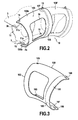
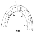
- the fairing 10 is divided into several adjacent sectors denoted 100, 100 '(see Figures 2 to 5 ) or 200, 200 ', 200 "(see figure 6 ).
- these adjacent sectors are all identical, which allows them to be mass-produced.
- the number of sectors can vary.
- each sector having a single opening 16, or divide the fairing into nine, six, or even three sectors, each sector then having respectively two, three or six openings 16.
- the greater the number of sectors is weak, the assembly of fairing 10 is fast, but less areas are flexible.
- the more the number of sectors is important, the more these sectors are flexible and the easier it is to get a good contact between the fixing edge of these sectors and the outer walls 3 and inner 2, but the assembly of the fairing It takes time.
- the greater the number of sectors the better the vibration damping.
- each fairing sector has at least one opening allowing the passage of at least one fuel injector.
- the Figures 2 to 5 represent exemplary embodiments where each sector 100, 100 'has a single opening 16 for the passage of a fuel injector 14.
- the figure 6 represents an exemplary embodiment where each sector 200, 200 ', 200 "has three openings 16, each opening allowing the passage of a fuel injector 14.
- each fairing sector has a or several openings, each opening being sufficiently circumferentially extended to allow the passage of several fuel injectors.
- each sector 100 covers, upstream, the chamber bottom 11 and includes inner fixing edges 100a and outer 100b fixed to the inner fixing flange 11a and outer 11b of the chamber bottom 11 and to the upstream edges 2a and 3b of the inner walls 2 and outer 3, at different attachment points. More specifically, the outer binding edge 100b (or inner 100a) of the fairing sector, the upstream edge 3b (or 2a) of the outer wall 3 (or inner 2), and the outer fixing flange 11b (or inner 11a). from the bottom of the room 11 are superimposed from the outside to the inside of the combustion chamber 8, and are traversed by holes coinciding with each other and through which have passed bolts 15. These bolts 15 maintain said edges 100a, 100b, 3a, 3b and flanges 11a, 11b, assembled together and are distributed in two concentric circles around the axis X.
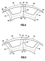
- Adjacent sectors 100 and 100 'of Figures 2 to 5 each have two side edges 101, 102 and 101 ', 102' and when these sectors are joined, the side edge 101 of the sector 100 overlaps the side edge 102 'of the adjacent sector 100'. Thus, there is no circumferential space between the assembled sectors, which limits or even avoid air leakage between these sectors.
- each sector 100 comprises on its lateral edge 101 a lip 105 connected to the rest of the sector by a riser 107. It is this lip 105 which covers the lateral edge 102 'of the adjacent sector. 100 ', when the sectors 100 and 100' are assembled (see figures 2 , 4 and 5 ).
- the riser 107 can also serve as a stop for the lateral edge 102 'of the sector 100' and thus facilitate the establishment of the sectors relative to each other.
- the inner fixing edges 100a and outer 100b of each sector 100 are each fixed at two fixing points. These two attachment points are respectively located at the side edges 101 and 102 of the sector 100. More specifically, these two attachment points are made by means of a bolt 15 passed through a hole 108 or 109 crossing the edge. concerned. At least one of said holes is oblong, its largest dimension being oriented in the circumferential direction of the shroud 10.
- This oblong hole 108 allows a distance or a relative approximation of the bolts 15, such spacing / approximation can be caused during assembly of the sector 100 on the walls 2 and 3 or, in operation, by the difference in expansion between the walls 2 and 3 and / or the bottom 11 of the chamber 8 and the sector 100. This avoids the occurrence of stresses in the sector 100 .
- two circular holes 109 are respectively formed in the fixing edges 100a and 100b, on the side of the lateral edge 102, while two oblong holes 108 are respectively arranged in the fixing edges 100a and 100b, on the side of the lateral edge 101. More precisely, the two oblong holes 108 pass through the lip 105.
- the figure 5 is a view similar to that of the figure 4 representing two adjacent sectors 100, 100 'of another example of a fairing according to the invention.
- the fairing areas 100, 100 'of the figure 5 differ from those of the figure 4 only with regard to their fixing points at the bottom of the chamber. Indeed, in the example of figure 5 , the inner fixing edges 100a and outer 100b of each sector 100 are each fixed at a single point of attachment. This fixing point is made with a bolt 15, passed through a hole 111 which passes through the fastening edge 100a or 100b of the sector. This makes it possible to limit as much as possible the number of bolts 15 and holes 111, and thus to minimize the mass and the manufacturing cost of the sector 100.
- said attachment point is situated outside the zone of overlap of the sectors 100, but is positioned in the vicinity of this zone. In this way, a part of the clamping forces of the bolt 15 is used so that the side edge 101 of the sector 100 exerts pressure on the side edge 102 'of the adjacent sector 100' and maintains the sector 100 'in position.
- the assembly of the fairing 10 of the figure 5 can be achieved as follows: first, the sector 100 is fixed on the chamber bottom 11, without completely tightening the bolts 15 through the openings 111, then the side edge 102 'of the adjacent sector 100' is passed under the lip 105. Then, the second sector 100 'is fixed without completely tightening the bolts 15 passing through the openings 111', so as to be able to pass under the lip 105 'of the sector 100' the lateral edge of another adjacent sector, not shown, And so on. Once all sectors are in place, bolts 15 are fully used.
- the first sector 100 when partially fixed (i.e. by incomplete clamping of the bolt 15) maintains the second sector 100 'while it is not yet bolted to the chamber bottom. This facilitates the assembly of the fairing areas.
Landscapes
- Engineering & Computer Science (AREA)
- Chemical & Material Sciences (AREA)
- Combustion & Propulsion (AREA)
- Mechanical Engineering (AREA)
- General Engineering & Computer Science (AREA)
- Turbine Rotor Nozzle Sealing (AREA)
- Fuel-Injection Apparatus (AREA)
Applications Claiming Priority (1)
| Application Number | Priority Date | Filing Date | Title |
|---|---|---|---|
| FR0754051A FR2914399B1 (fr) | 2007-03-27 | 2007-03-27 | Carenage pour fond de chambre de combustion. |
Publications (2)
| Publication Number | Publication Date |
|---|---|
| EP1978305A1 true EP1978305A1 (de) | 2008-10-08 |
| EP1978305B1 EP1978305B1 (de) | 2009-10-07 |
Family
ID=38802680
Family Applications (1)
| Application Number | Title | Priority Date | Filing Date |
|---|---|---|---|
| EP08153166A Active EP1978305B1 (de) | 2007-03-27 | 2008-03-21 | Verkleidung für den Boden einer Brennkammer |
Country Status (4)
| Country | Link |
|---|---|
| US (1) | US7861531B2 (de) |
| EP (1) | EP1978305B1 (de) |
| DE (1) | DE602008000191D1 (de) |
| FR (1) | FR2914399B1 (de) |
Cited By (1)
| Publication number | Priority date | Publication date | Assignee | Title |
|---|---|---|---|---|
| EP3404208A1 (de) * | 2017-05-05 | 2018-11-21 | Rolls-Royce Deutschland Ltd & Co KG | Strömungsleitvorrichtung und verfahren zur ausbildung einer strömungsleitvorrichtung |
Families Citing this family (14)
| Publication number | Priority date | Publication date | Assignee | Title |
|---|---|---|---|---|
| FR2918444B1 (fr) * | 2007-07-05 | 2013-06-28 | Snecma | Deflecteur de fond de chambre, chambre de combustion le comportant et moteur a turbine a gaz en etant equipe |
| FR2918443B1 (fr) * | 2007-07-04 | 2009-10-30 | Snecma Sa | Chambre de combustion comportant des deflecteurs de protection thermique de fond de chambre et moteur a turbine a gaz en etant equipe |
| FR2921462B1 (fr) * | 2007-09-21 | 2012-08-24 | Snecma | Chambre de combustion annulaire de moteur a turbine a gaz |
| JP5276345B2 (ja) * | 2008-03-28 | 2013-08-28 | 三菱重工業株式会社 | ガスタービン及びガスタービンの燃焼器挿入孔形成方法 |
| FR2964725B1 (fr) * | 2010-09-14 | 2012-10-12 | Snecma | Carenage aerodynamique pour fond de chambre de combustion |
| DE102011014670A1 (de) * | 2011-03-22 | 2012-09-27 | Rolls-Royce Deutschland Ltd & Co Kg | Segmentierter Brennkammerkopf |
| DE102014213302A1 (de) * | 2014-07-09 | 2016-01-14 | Rolls-Royce Deutschland Ltd & Co Kg | Brennkammer einer Gasturbine mit verschraubtem Brennkammerkopf |
| GB201501817D0 (en) * | 2015-02-04 | 2015-03-18 | Rolls Royce Plc | A combustion chamber and a combustion chamber segment |
| GB201613110D0 (en) * | 2016-07-29 | 2016-09-14 | Rolls Royce Plc | A combustion chamber |
| US10816213B2 (en) | 2018-03-01 | 2020-10-27 | General Electric Company | Combustor assembly with structural cowl and decoupled chamber |
| KR102068305B1 (ko) * | 2018-03-19 | 2020-01-20 | 두산중공업 주식회사 | 연소기 및 이를 포함하는 가스 터빈 |
| CN112576320B (zh) * | 2020-12-07 | 2023-01-17 | 中国航发沈阳发动机研究所 | 一种协调冷热态变形的导流罩结构 |
| CN116642200A (zh) * | 2022-02-15 | 2023-08-25 | 通用电气公司 | 用于燃烧器的圆顶的集成圆顶偏转器构件 |
| US12209750B2 (en) * | 2023-02-14 | 2025-01-28 | Collins Engine Nozzles, Inc. | Line replaceable fuel injector panels with single hatch installation |
Citations (3)
| Publication number | Priority date | Publication date | Assignee | Title |
|---|---|---|---|---|
| EP0488557A1 (de) * | 1990-11-26 | 1992-06-03 | General Electric Company | Zwillingsbrennkammer |
| US6148600A (en) | 1999-02-26 | 2000-11-21 | General Electric Company | One-piece sheet metal cowl for combustor of a gas turbine engine and method of configuring same |
| EP1265031A1 (de) | 2001-06-06 | 2002-12-11 | Snecma Moteurs | Befestigung von metallischen Aufsätzen auf CMC-Turbomachinenbrennkammerwänden |
Family Cites Families (10)
| Publication number | Priority date | Publication date | Assignee | Title |
|---|---|---|---|---|
| US3854285A (en) * | 1973-02-26 | 1974-12-17 | Gen Electric | Combustor dome assembly |
| US4843825A (en) * | 1988-05-16 | 1989-07-04 | United Technologies Corporation | Combustor dome heat shield |
| FR2686683B1 (fr) * | 1992-01-28 | 1994-04-01 | Snecma | Turbomachine a chambre de combustion demontable. |
| US5623827A (en) * | 1995-01-26 | 1997-04-29 | General Electric Company | Regenerative cooled dome assembly for a gas turbine engine combustor |
| US6550251B1 (en) * | 1997-12-18 | 2003-04-22 | General Electric Company | Venturiless swirl cup |
| US6557349B1 (en) * | 2000-04-17 | 2003-05-06 | General Electric Company | Method and apparatus for increasing heat transfer from combustors |
| US7222488B2 (en) * | 2002-09-10 | 2007-05-29 | General Electric Company | Fabricated cowl for double annular combustor of a gas turbine engine |
| FR2897144B1 (fr) * | 2006-02-08 | 2008-05-02 | Snecma Sa | Chambre de combustion de turbomachine a fentes tangentielles |
| FR2897145B1 (fr) * | 2006-02-08 | 2013-01-18 | Snecma | Chambre de combustion annulaire de turbomachine a fixations alternees. |
| FR2897417A1 (fr) * | 2006-02-10 | 2007-08-17 | Snecma Sa | Chambre de combustion annulaire d'une turbomachine |
-
2007
- 2007-03-27 FR FR0754051A patent/FR2914399B1/fr not_active Expired - Fee Related
-
2008
- 2008-03-21 DE DE602008000191T patent/DE602008000191D1/de active Active
- 2008-03-21 EP EP08153166A patent/EP1978305B1/de active Active
- 2008-03-21 US US12/053,091 patent/US7861531B2/en active Active
Patent Citations (3)
| Publication number | Priority date | Publication date | Assignee | Title |
|---|---|---|---|---|
| EP0488557A1 (de) * | 1990-11-26 | 1992-06-03 | General Electric Company | Zwillingsbrennkammer |
| US6148600A (en) | 1999-02-26 | 2000-11-21 | General Electric Company | One-piece sheet metal cowl for combustor of a gas turbine engine and method of configuring same |
| EP1265031A1 (de) | 2001-06-06 | 2002-12-11 | Snecma Moteurs | Befestigung von metallischen Aufsätzen auf CMC-Turbomachinenbrennkammerwänden |
Cited By (2)
| Publication number | Priority date | Publication date | Assignee | Title |
|---|---|---|---|---|
| EP3404208A1 (de) * | 2017-05-05 | 2018-11-21 | Rolls-Royce Deutschland Ltd & Co KG | Strömungsleitvorrichtung und verfahren zur ausbildung einer strömungsleitvorrichtung |
| US10954885B2 (en) | 2017-05-05 | 2021-03-23 | Rolls-Royce Deutschland Ltd & Co Kg | Flow guiding device and method for forming a flow guiding device |
Also Published As
| Publication number | Publication date |
|---|---|
| DE602008000191D1 (de) | 2009-11-19 |
| US20080236164A1 (en) | 2008-10-02 |
| US7861531B2 (en) | 2011-01-04 |
| FR2914399A1 (fr) | 2008-10-03 |
| EP1978305B1 (de) | 2009-10-07 |
| FR2914399B1 (fr) | 2009-10-02 |
Similar Documents
| Publication | Publication Date | Title |
|---|---|---|
| EP1978305B1 (de) | Verkleidung für den Boden einer Brennkammer | |
| EP2042806B1 (de) | Brennkammer einer Strömungsmaschine | |
| CA2544784C (fr) | Module de turbine pour moteur a turbine a gaz | |
| CA2577520C (fr) | Chambre de combustion annulaire d'une turbomachine | |
| EP2318665B1 (de) | Hochdruckturbine mit einem rutschenden stator | |
| EP3569929B1 (de) | Einheit für eine brennkammer eines turbotriebwerks | |
| CA2577514A1 (fr) | Chambre de combustion annulaire d'une turbomachine | |
| CA2740660A1 (fr) | Rotor deshuileur pour turbomachine | |
| FR2961251A1 (fr) | Moyeu de carter intermediaire pour turboreacteur d'aeronef comprenant des moyens d'evacuation de debris ameliores | |
| EP2003399A2 (de) | Brennkammer einer Strömungsmaschine mit helikoidaler Luftströmung | |
| EP1950497B1 (de) | Verteilerkammer für gasturbinenmotor, brennkammer und gasturbinenmotor, der diese umfasst | |
| EP3784958B1 (de) | Einspritzsystem für eine annulare verbrennungskammer einer gasturbine | |
| CA2602938C (fr) | Chambre de combustion annulaire d'une turbomachine | |
| FR2990001A1 (fr) | Assemblage d'un echangeur thermique au sein d'un carter intermediaire de turboreacteur | |
| CA2619422C (fr) | Chambre de combustion d'une turbomachine | |
| WO2009133322A1 (fr) | Chambre annulaire de combustion pour turbomachine | |
| FR3009747A1 (fr) | Chambre de combustion de turbomachine pourvue d'un passage d'entree d'air ameliore en aval d'un orifice de passage de bougie | |
| FR2909163A1 (fr) | Carenage de chambre de combustion de turbomachine. | |
| EP3928034B1 (de) | Brennkammer für eine turbomaschine | |
| FR2910597A1 (fr) | Carenage pour fond de chambre de combustion | |
| EP3983661B1 (de) | Vorrichtung zur kühlung des gehäuses einer turbomaschine | |
| EP3953568B1 (de) | Gegenläufige turbine einer turbomaschine und verfahren zur montage einer äusseren laufenden beschaufelung einer gegenläufigen turbine | |
| EP3568638B1 (de) | Brennkammer für einen turbinenmotor | |
| WO2024261434A1 (fr) | Systeme d'injection pour chambre de combustion de turbomachine a etancheite optimisee entre injecteur et traversee coulissante | |
| FR3098552A1 (fr) | Turbomachine comportant une structure et une structure interne d’un conduit d’ejection primaire fixee a ladite structure |
Legal Events
| Date | Code | Title | Description |
|---|---|---|---|
| PUAI | Public reference made under article 153(3) epc to a published international application that has entered the european phase |
Free format text: ORIGINAL CODE: 0009012 |
|
| 17P | Request for examination filed |
Effective date: 20080321 |
|
| AK | Designated contracting states |
Kind code of ref document: A1 Designated state(s): AT BE BG CH CY CZ DE DK EE ES FI FR GB GR HR HU IE IS IT LI LT LU LV MC MT NL NO PL PT RO SE SI SK TR |
|
| AX | Request for extension of the european patent |
Extension state: AL BA MK RS |
|
| GRAP | Despatch of communication of intention to grant a patent |
Free format text: ORIGINAL CODE: EPIDOSNIGR1 |
|
| AKX | Designation fees paid |
Designated state(s): DE FR GB IT |
|
| GRAS | Grant fee paid |
Free format text: ORIGINAL CODE: EPIDOSNIGR3 |
|
| GRAA | (expected) grant |
Free format text: ORIGINAL CODE: 0009210 |
|
| AK | Designated contracting states |
Kind code of ref document: B1 Designated state(s): DE FR GB IT |
|
| REG | Reference to a national code |
Ref country code: GB Ref legal event code: FG4D Free format text: NOT ENGLISH |
|
| REF | Corresponds to: |
Ref document number: 602008000191 Country of ref document: DE Date of ref document: 20091119 Kind code of ref document: P |
|
| PLBE | No opposition filed within time limit |
Free format text: ORIGINAL CODE: 0009261 |
|
| STAA | Information on the status of an ep patent application or granted ep patent |
Free format text: STATUS: NO OPPOSITION FILED WITHIN TIME LIMIT |
|
| 26N | No opposition filed |
Effective date: 20100708 |
|
| REG | Reference to a national code |
Ref country code: FR Ref legal event code: PLFP Year of fee payment: 9 |
|
| REG | Reference to a national code |
Ref country code: FR Ref legal event code: PLFP Year of fee payment: 10 |
|
| REG | Reference to a national code |
Ref country code: FR Ref legal event code: CD Owner name: SAFRAN AIRCRAFT ENGINES, FR Effective date: 20170719 |
|
| REG | Reference to a national code |
Ref country code: FR Ref legal event code: PLFP Year of fee payment: 11 |
|
| PGFP | Annual fee paid to national office [announced via postgrant information from national office to epo] |
Ref country code: IT Payment date: 20250218 Year of fee payment: 18 |
|
| PGFP | Annual fee paid to national office [announced via postgrant information from national office to epo] |
Ref country code: GB Payment date: 20260317 Year of fee payment: 19 |
|
| PGFP | Annual fee paid to national office [announced via postgrant information from national office to epo] |
Ref country code: DE Payment date: 20260320 Year of fee payment: 19 |
|
| PGFP | Annual fee paid to national office [announced via postgrant information from national office to epo] |
Ref country code: FR Payment date: 20260324 Year of fee payment: 19 |