EP1978312A2 - Récipient à isolation thermique et son procédé de fabrication - Google Patents
Récipient à isolation thermique et son procédé de fabrication Download PDFInfo
- Publication number
- EP1978312A2 EP1978312A2 EP08005335A EP08005335A EP1978312A2 EP 1978312 A2 EP1978312 A2 EP 1978312A2 EP 08005335 A EP08005335 A EP 08005335A EP 08005335 A EP08005335 A EP 08005335A EP 1978312 A2 EP1978312 A2 EP 1978312A2
- Authority
- EP
- European Patent Office
- Prior art keywords
- heat
- insulating
- container
- outer covering
- inside container
- Prior art date
- Legal status (The legal status is an assumption and is not a legal conclusion. Google has not performed a legal analysis and makes no representation as to the accuracy of the status listed.)
- Granted
Links
Images


Classifications
-
- F—MECHANICAL ENGINEERING; LIGHTING; HEATING; WEAPONS; BLASTING
- F24—HEATING; RANGES; VENTILATING
- F24H—FLUID HEATERS, e.g. WATER OR AIR HEATERS, HAVING HEAT-GENERATING MEANS, e.g. HEAT PUMPS, IN GENERAL
- F24H1/00—Water heaters, e.g. boilers, continuous-flow heaters or water-storage heaters
- F24H1/18—Water-storage heaters
- F24H1/181—Construction of the tank
- F24H1/182—Insulation
-
- F—MECHANICAL ENGINEERING; LIGHTING; HEATING; WEAPONS; BLASTING
- F01—MACHINES OR ENGINES IN GENERAL; ENGINE PLANTS IN GENERAL; STEAM ENGINES
- F01P—COOLING OF MACHINES OR ENGINES IN GENERAL; COOLING OF INTERNAL-COMBUSTION ENGINES
- F01P11/00—Component parts, details, or accessories not provided for in, or of interest apart from, groups F01P1/00 - F01P9/00
- F01P11/02—Liquid-coolant filling, overflow, venting, or draining devices
- F01P11/029—Expansion reservoirs
-
- F—MECHANICAL ENGINEERING; LIGHTING; HEATING; WEAPONS; BLASTING
- F24—HEATING; RANGES; VENTILATING
- F24H—FLUID HEATERS, e.g. WATER OR AIR HEATERS, HAVING HEAT-GENERATING MEANS, e.g. HEAT PUMPS, IN GENERAL
- F24H9/00—Details
- F24H9/12—Arrangements for connecting heaters to circulation pipes
-
- F—MECHANICAL ENGINEERING; LIGHTING; HEATING; WEAPONS; BLASTING
- F28—HEAT EXCHANGE IN GENERAL
- F28D—HEAT-EXCHANGE APPARATUS, NOT PROVIDED FOR IN ANOTHER SUBCLASS, IN WHICH THE HEAT-EXCHANGE MEDIA DO NOT COME INTO DIRECT CONTACT
- F28D20/00—Heat storage plants or apparatus in general; Regenerative heat-exchange apparatus not covered by groups F28D17/00 or F28D19/00
- F28D20/0034—Heat storage plants or apparatus in general; Regenerative heat-exchange apparatus not covered by groups F28D17/00 or F28D19/00 using liquid heat storage material
-
- F—MECHANICAL ENGINEERING; LIGHTING; HEATING; WEAPONS; BLASTING
- F28—HEAT EXCHANGE IN GENERAL
- F28F—DETAILS OF HEAT-EXCHANGE AND HEAT-TRANSFER APPARATUS, OF GENERAL APPLICATION
- F28F2270/00—Thermal insulation; Thermal decoupling
-
- Y—GENERAL TAGGING OF NEW TECHNOLOGICAL DEVELOPMENTS; GENERAL TAGGING OF CROSS-SECTIONAL TECHNOLOGIES SPANNING OVER SEVERAL SECTIONS OF THE IPC; TECHNICAL SUBJECTS COVERED BY FORMER USPC CROSS-REFERENCE ART COLLECTIONS [XRACs] AND DIGESTS
- Y02—TECHNOLOGIES OR APPLICATIONS FOR MITIGATION OR ADAPTATION AGAINST CLIMATE CHANGE
- Y02E—REDUCTION OF GREENHOUSE GAS [GHG] EMISSIONS, RELATED TO ENERGY GENERATION, TRANSMISSION OR DISTRIBUTION
- Y02E60/00—Enabling technologies; Technologies with a potential or indirect contribution to GHG emissions mitigation
- Y02E60/14—Thermal energy storage
-
- Y—GENERAL TAGGING OF NEW TECHNOLOGICAL DEVELOPMENTS; GENERAL TAGGING OF CROSS-SECTIONAL TECHNOLOGIES SPANNING OVER SEVERAL SECTIONS OF THE IPC; TECHNICAL SUBJECTS COVERED BY FORMER USPC CROSS-REFERENCE ART COLLECTIONS [XRACs] AND DIGESTS
- Y10—TECHNICAL SUBJECTS COVERED BY FORMER USPC
- Y10T—TECHNICAL SUBJECTS COVERED BY FORMER US CLASSIFICATION
- Y10T29/00—Metal working
- Y10T29/49—Method of mechanical manufacture
- Y10T29/49826—Assembling or joining
Definitions
- the present invention relates to a heat-insulating container for storing and maintaining the temperature of liquids, and more specifically relates to a heat-insulating container for storing and maintaining the temperature of cooling water used in vehicle engines.
- heat-accumulating tanks comprising an inner cylinder which stores a liquid, and an outer cylinder which accommodates the inner cylinder therein, wherein a heat-insulating space in a vacuum state is formed between the outer cylinder and the inner cylinder, are known as heat-insulating containers.
- These containers are necessary in order to store and maintain the temperature of cooling water for use in vehicle engines (long-life coolant; hereafter abbreviated as "LLC”), and to accelerate the warm-up of the engine by circulating the temperature-controlled LLC when the engine is started (Japanese Laid-Open Patent Application No. 2006-104974 ).
- a hot water storage tank having an inside container that accommodates a liquid, and an outer case that envelops the inside container, wherein a vacuum heat-insulating material and a sheet-form heat insulating material are disposed in a space formed by the inside container and the outer case (Japanese Laid-Open Patent Application No. 2005-226965 ).
- a structure in which a vacuum heat-insulating material is disposed between an inner cylinder and an outer cylinder, and an electrical heater is disposed inside is known as a heat-insulating container for storing and maintaining the temperature of a liquid (Japanese Laid-Open Utility Model Application No. 61-138954 ).
- a temperature-maintaining performance wherein the temperature of the LLC heated by the preheating of the engine is maintained at a high temperature until the engine is next started is required in order to improve the fuel consumption during engine starting.
- a demand also exists for a reduction in the manufacturing costs along with a reduction in the vehicle prime cost. Since this heat-insulating container is installed inside an engine compartment, there is a strong requirement for a configuration that can be accommodated inside the limited space inside an engine compartment, which varies according to the vehicle involved.
- a heat-insulating space in a vacuum state is formed between an inside container and an outer container made of a metal such as stainless steel.
- the inside container and the outer container are integrally formed by welding or spinning.
- the manufacturing cost is increased, and the heat is emitted by heat bridging (the heat bridging effect) from the metal joint parts between the inside container and the outer container and it becomes impossible to obtain a sufficient temperature-maintaining effect.
- thin stainless steel sheets of 1 mm or less are respectively used for the inside container and outer container in order to suppress the heat loss caused by heat bridging, and the shape is limited to a cylindrical one in order to prevent deformation caused by the pressure difference between the heat-insulating space and the atmosphere and there are limits in forming a shape suitable for the limited space inside the engine compartment.
- the heat-insulating container indicated in Japanese Laid-Open Patent Application No. 2005-226965 has a structure in which a vacuum heat-insulating material and sheet-form heat-insulating material are disposed in a space formed by an inside container that accommodates a liquid and an outer covering case that envelops the inside container. Since a gap is generated between the inside container, and the vacuum heat-insulating material and the sheet-form heat-insulating material, a high-performance heat-insulating effect cannot be obtained.
- the heat-insulating container indicated in Japanese Laid-Open Utility Model Application No. 61-138954 has a structure in which a vacuum heat-insulating plate is disposed between an inner cylinder and an outer cylinder.
- a heat-insulating container for storing and maintaining the temperature of a liquid, characterized in comprising: an inside container having an inlet and outlet opening part for the liquid; and a sheet-form outer covering which accommodates the inside container; wherein a heat-insulating material is sealed between the outer covering and the inside container, and a heat-insulating space in which the pressure is reduced is formed; an upper surface of a flange part disposed on the inlet and outlet opening part and an upper surface of the heat-insulating material constitute substantially the same plane; and the upper surface of the flange parts and the outer covering are joined.
- a heat-insulating container wherein the inside container is made of metal; the outer covering is a laminate film having an adhesive layer; and the adhesive layer is an ethylene-vinyl alcohol copolymer, nylon, polyvinyl alcohol, polyvinylidene chloride, or polyester.
- a heat-insulating container wherein the inside container is made of a resin; the outer covering is a laminate film having an adhesive layer; a gas barrier layer is disposed on the surface of the inside container; and the adhesive layer is an ethylene-vinyl alcohol copolymer, nylon, polyvinyl alcohol, polyvinylidene chloride, or polyester.
- a heat-insulating container wherein the inside container is made of a resin comprising a polyethylene or polypropylene; the outer covering is a laminate film having an adhesive layer; and a gas barrier layer is disposed on a surface of the inside container.
- a heat-insulating container wherein the heat-insulating material comprises an inorganic fiber that is either glass wool, rock wool, or ceramic fiber, or a mixture of these fibers; an adsorbent having a three-layer structure comprising calcium oxide, a barium/lithium alloy, and cobalt oxide is sealed inside the heat-insulating space; and an intermediate layer of the adsorbent is the barium/lithium alloy.
- a heat-insulating container wherein a portion of the inlet and outlet opening part disposed on the inside container that is above the upper surfaces of the flange parts is removable.
- a method for manufacturing a heat-insulating container for storing and maintaining the temperature of a liquid wherein a heat-insulating material for covering the area surrounding an inside container which has an inlet and outlet opening part for the liquid is formed at a thickness which is such that an upper surface of the heat-insulating material and an upper surface of a flange part disposed on the inlet and outlet opening part constitute substantially the same plane; the heat-insulating material is covered by an outer covering in which a hole through which the inlet and outlet opening part passes is formed; the upper surface of the flange part and area surrounding the hole formed in the outer covering are joined; and a space between the inside container and the outer covering is tightly sealed in a state of reduced pressure.
- a method for manufacturing a heat-insulating container wherein the outer covering is a bag-form laminate film; and an opening of the bag-form laminate film is joined inside a vacuum atmosphere after the upper surfaces of the flange parts and the outer covering have been joined.
- a ninth aspect of the present invention there is provided a method for manufacturing a heat-insulating container wherein a portion of the inlet and outlet opening part disposed on the inside container that is above the upper surface of the flange part is removable.
- the present invention offers the following effects.
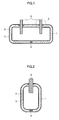
- FIG. 1 shows a sectional view of a heat-insulating container in which a portion for inlet and a portion for outlet of a liquid inlet and outlet opening part 5 are installed at separate positions.
- FIG. 2 shows a sectional view of a heat-insulating container in which a portion for inlet and a portion for outlet of a liquid inlet and outlet opening part 5 are integrated by the installation of a partition part.
- a heat-insulating container in which the periphery of the inside container 1 is covered by a heat-insulating material 2 comprising inorganic fibers, the periphery of the heat-insulating material 2 is covered by an outer covering 3 comprising a sheet-form laminate film, a gas adsorbing material 4 is sealed between the inside container 1 and the outer covering 3, and the space between the inside container 1 and the outer covering 3 is in a state of reduced pressure.
- state of reduced pressure is meant a state in which the gas pressure is reduced to a pressure lower than atmospheric pressure in order to improve the heat insulating properties.
- a gas pressure refers to a pressure of 0.01 to 100 Pa, and is preferably a pressure of 0.1 to 10 Pa.
- FIGS. 3 through 5 show containers in which rim-form flanges 6 are formed on the liquid inlet and outlet opening part 5.
- the heat-insulating material 2 covers the inside container 1 so that the upper surface of the heat-insulating material 2 and the upper surfaces of the flanges 6 constitute substantially the same plane.
- the outer covering 3 is layered on the substantially same plane. The outer covering 3 and the upper surfaces of the flanges 6 are joined. As a result, the bonding work of the joint parts of the outer covering 3 and the flanges 6 is facilitated.
- the liquid inlet and outlet opening part 5 shown in FIG. 5 has a structure in which the parts of the fluid inlet and outlet part 5 that are above the upper surfaces of the flanges 6 are removable. In this case, O-rings 10 are interposed between the ports 9 for liquid inlet and outlet openings and the flanges 6 in order to maintain the air-tightness.
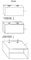
- FIGS. 6 , 7A and 7B The manufacturing procedure used in order to realize the structure of the heat-insulating container of the present invention is shown in FIGS. 6 , 7A and 7B .
- FIG. 6 shows the outer covering 3 used in this manufacturing process. Holes 3b, 3b which engage with the liquid inlet and outlet opening part 5 of the inside container 1 are formed in the bottom surface 3a of the bag-form outer covering 3.
- the heat-insulating container is manufactured according to the procedure shown in FIGS. 7A and 7B , using such an outer covering 3.
- the periphery of the inside container 1 is covered by a blanket-form heat-insulating material 2 comprising a glass wool to a thickness which is such that the upper surface of the heat-insulating material 2 is equal to the positions of the upper surfaces of the flanges 6 formed in the fluid inlet and outlet opening part 5.
- the inside container 1 and the heat-insulating material 2 are covered by an outer covering 3 comprising a bag-form laminate film, and the positions of holes 3b, 3b formed in the outer covering 3 and the fluid inlet and outlet opening part 5 are engaged.
- the outer covering 3 and the flanges 6 disposed on the fluid inlet and outlet opening part 5 are joined (thermally welded) using a ring-form heater 15.
- a gas adsorbent 4 is sealed between the inside container 1 and the outer covering 3. Then, the inside container 1 covered by the outer covering 3 is conveyed into a vacuum chamber not shown, and the open part of the outer covering 3 is joined (thermally welded) by a welding sealing heater 16 in a vacuum atmosphere at 10 Pa or less.
- the inside container 1 is made of either a synthetic resin or metal; from the standpoint of temperature-maintaining characteristics and vacuum maintaining characteristics, a metal is desirable. A stainless steel having low thermal conductivity is especially desirable. From the standpoint of manufacturing cost and forming a shape suitable for the limited spaces, a synthetic resin is desirable.
- Examples of synthetic resins that can be used include resins selected from a set consisting of acrylonitrile-butadiene-styrene copolymers (ABS), acrylonitrile-styrene copolymers (AS), EEA resins (EEA), epoxy resins (EP), ethylene-vinyl acetate polymers (EVA), ethylene-vinyl alcohol copolymer (EVOH), liquid crystal polymers (LCP), MBS resins (MBS), melamine formaldehydes (MMF), polyamides (PA), polybutylene terephthalamides (PBT), polycarbonate resins (PC), polyethylenes (PE), polyethylene terephthalates (PET), tetrafluoroethylene-perfluorovinylalkylvinyl ether polymers (PFA), polyimides (PI), polymethyl methacrylate (PMMA), polyacetal resins (POM), polypropylenes (PP), polyphthalamides (PPA), polyviny
- a gas barrier layer comprising a metal plating layer is formed on the surface of the inside container 1 in order to prevent permeation of gases, so that the degree of vacuum in the vacuum heat-insulating space formed between the inside container 1 and the outer covering 3 can be maintained for a long period of time.
- the gas barrier layer is a layer that suppresses permeation of gases.
- the oxygen permeation rate of the laminate film on which the gas barrier layer is laminated is 1.1 x 10 -11 m 3 /m 2 -s-MPa or less, and is preferably 1.1 x 10 -12 m 3 /m 2 -s-MPa or less.
- the thickness of such a gas barrier layer is, for example, 5 to 30 ⁇ m, and is preferably 6 to 15 ⁇ m.
- universally known plating can be used for the plating. For example, plating of laminating electrolytic copper on electroless nickel can be appropriately used.
- FIG. 8 The cross-sectional structure of the laminate film constituting the outer covering 3 is shown in FIG. 8 .
- a gas barrier layer is formed in the outer covering 3.
- a sheet-form outer covering 3 is suitably used.
- a laminate film with a multi-layer structure comprising a "protective layer 11/protective layer 12 (substrate layer 12)/gas barrier layer 13/adhesive layer 14" shown in FIG. 8 can be one example of such an outer covering 3.
- the thickness of such a laminate film is, for example, 45 to 120 ⁇ m, and is preferably 60 to 100 ⁇ m.
- the material forming the adhesive layer 14 there are no particular restrictions on the material forming the adhesive layer 14, as long as joining to the flanges 6 of the inside container 1 and joining of the adhesive layers 14 to each other is possible.
- a material having a low gas permeability is preferable.
- an ethylene-vinyl alcohol copolymer, nylon, polyvinyl alcohol, polyvinylidene chloride, or polyester is desirable, and it is especially desirable to use an ethylene-vinyl alcohol copolymer.
- the material of the adhesive layer 14 may be a polyethylene
- the material of the flanges 6 is a polypropylene
- the material of the adhesive layer 14 is a polypropylene or ethylene-vinyl alcohol
- the adhesive layer 14 be formed from an ethylene-vinyl alcohol.
- the thickness of the adhesive layer 13 is, for example, 10 to 70 ⁇ m, and is preferably 30 to 50 ⁇ m.
- the material forming the gas barrier layer 13 there are no particular restrictions on the material forming the gas barrier layer 13, as long as permeation of gases can be limited.
- a metal foil such as a stainless steel foil or aluminum foil may be used.
- An aluminum foil which has a low gas permeability and a relatively low thermal conductivity is especially desirable for use.
- the thickness of the gas barrier layer 13 is, for example, 5 to 30 ⁇ m, and is preferably 6 to 15 ⁇ m.
- the protective layers 11, 12 are layers that protect the gas barrier layer 13. For example, these layers 11, 12 prevent the formation of pinhole cracks or the like in the aluminum foil that forms the gas barrier layer 13, and ensure the gas permeation preventive effect. Synthetic resins such as polyesters or nylons can be ideally used as the material that forms such protective layers 11, 12.
- the thickness of the protective layers 11, 12 is, for example, 10 to 50 ⁇ m, and is preferably 20 to 40 ⁇ m. If necessary, furthermore, the protective layers 11, 12 can be formed as a plurality of layers as shown in FIG. 8 . By using a construction which has a plurality of layers (e.g., the protective layer 11 and the protective layer 12 shown in FIG. 8 ), it is possible to add functions that take advantage of the respective characteristics of the resins used in the formation of the respective layers to the protective layers 11, 12.
- heat-insulating material 2 that envelops the inside container 1
- materials that are universally known as heat-insulating materials can be used.
- an organic porous body such as a polystyrene foam, a molded body containing ceramic powders such as calcium silicate, silica or alumina, or inorganic fiber heat-insulating materials comprising one or more types of inorganic fibers such as glass wool, rock wool, or ceramic fibers
- ceramic powders such as calcium silicate, silica or alumina
- inorganic fiber heat-insulating materials comprising one or more types of inorganic fibers such as glass wool, rock wool, or ceramic fibers
- glass wool with a mean fiber diameter of 5 ⁇ m or less from which the adsorbed water content has been removed in a high-temperature atmosphere are especially desirable for use.
- Such heat-insulating materials may be used singly or in combinations of two or more materials.
- a gas adsorbent 4 may be sealed inside the vacuum heat-insulating layer in order to prevent a drop in the degree of vacuum of the vacuum heat-insulating layer caused by gases generated from the heat-insulating material 2, gases invading from the outside air by permeating the resin of the joint parts between the outer covering 3 and the inside container 1, or the like.
- a gas adsorbent having a three-layer structure comprising a calcium oxide layer that adsorbs moisture, a barium/lithium alloy layer that adsorbs oxygen and nitrogen, and a cobalt oxide layer that adsorbs hydrogen is used as the gas adsorbent 4.
- the barium/lithium alloy layer also has the function of adsorbing moisture in addition to oxygen and hydrogen. Accordingly, by using a structure in which the barium/lithium alloy layer is an intermediate layer between the calcium oxide layer and the cobalt oxide layer, it is possible to utilize the adsorption characteristics of the respective layers with good efficiency.
- the amount of glass wool that is wrapped around the surface of the inside container 1 is determined from the heat-insulating performance that is required in the heat-insulating container. For example, in a heat-insulating container equipped with vacuum heat-insulating layer having a thickness of 10 mm and wrapped with glass wool at the rate of 0.25 g/cm 2 , a vacuum heat-insulating layer having a thickness of 5 mm and wrapped with glass wool at the rate of 0.13 g/cm 2 , or a vacuum heat-insulating layer having a thickness of 15 mm and wrapped with glass wool at the rate of 0.38 g/cm 2 , when water at 95°C was poured and the water temperature was measured after 12 hours had passed, the result obtained was approximately 70°C in the case of a thickness of 5 mm, approximately 78°C in the case of a thickness of 10 mm, and approximately 82°C in the case of a thickness of 15 mm.
- FIGS. 9A and 9B are descriptive views showing other aspects of the heat-insulating container of the present invention.
- removable ports 9 for liquid inlet and outlet openings are used as the upper parts of the liquid inlet and outlet opening part 5 shown in FIG. 5 .
- a blanket-form heat-insulating material 2 comprising a glass wool to a thickness which is such that the upper surface of the heat-insulating material 2 reaches the positions of the upper surfaces of the flanges 6 disposed on the fluid inlet and outlet opening part 5.
- an outer covering 3 comprising a bag-form laminate film.
- the positions of the holes 3b formed in the outer covering 3 and the fluid inlet and outlet opening part 5 are engaged, and the outer covering 3 and flanges 6 disposed on the fluid inlet and outlet opening part 5 are thermally welded using a ring-form heater 15.
- a gas adsorbent 4 is sealed between the inside container 1 and the outer covering 3.
- the inside container 1 covered by the outer covering 3 is conveyed into a vacuum chamber (not shown), and the open part of the outer covering 3 is joined (thermally welded) by a welding and sealing heater 16 in a vacuum atmosphere at 10 Pa or less.
- the ports 9 for liquid inlet and outlet openings are attached with O-rings 10 interposed between the liquid inlet and outlet opening part 5 of the inside container 1 that has been brought out from the vacuum chamber. This enables the inside container 1 covered by the heat-insulating material 2 to be easily be inserted into the outer covering 3 regardless of the shape of the bag-form outer covering 3.
- a rectangular polyethylene container having an internal volume of approximate 2.6 L and a thickness of 8 mm was used as the inside container 1 of the present invention.
- Liquid inlet and outlet opening part 5 having an external diameter of 18.5 mm, an internal diameter of 13 mm, and a height of 30 mm were formed in one surface of the inside container 1.
- Flanges 6 having an external diameter of 12 mm and a thickness of 3 mm were formed on the inlet and outlet opening part 5.
- ABS resin layers were formed on the surfaces of the inside container 1 except at the surfaces of the flanges 6. Next, an electroless nickel plating layer was formed, and an electrolytic copper plating layer was further formed, so that a gas barrier layer was formed.
- a film having a multi-layer structure composed of a polyethylene terephthalate layer (12 ⁇ m) constituting a protective layer 11, a nylon layer (15 ⁇ m) constituting a protective layer 12, an aluminum foil (6 ⁇ m) constituting a gas barrier layer 13, and a polyethylene layer (50 ⁇ m) constituting an adhesive layer 14 was used as the laminate film constituting the outer covering 3. Furthermore, a film formed by forming this laminate film into a bag shape was used as the outer covering 3.
- a glass wool (white wool manufactured by Asahi Fiberglass) was used as the fiber heat-insulating material 2, and a getter material (COMB03GETTER manufactured by SAES Getters) was used as the gas adsorbent 4.
- a getter material (COMB03GETTER manufactured by SAES Getters) was used as the gas adsorbent 4.
- the periphery of the polyethylene container constituting the inside container 1 was covered by the glass wool to a thickness which was such that the upper surface of the glass wool reached the positions of the upper surfaces of the flanges 6 disposed on the inlet and outlet opening part 5 of the inside container 1.
- the density of the glass wool in this case was approximately 0.25 g/cm 2 with respect to the surface area of the inside container 1.
- the inside container 1 and the glass wool were allowed to stand for 24 hours in an oven at 120°C, and the moisture contained in the glass wool was evaporated.
- the inside container 1 was conveyed into an argon atmosphere after drying, and was accommodated into a bag-form outer covering 3 formed from the laminate film.
- a single getter material (approximately 7 g) constituting the gas adsorbent 4 was loaded into the space between the inside container 1 and the laminate film.
- the inside container 1 and the laminate film were conveyed into the vacuum chamber, and the pressure inside the vacuum chamber was reduced to 10 Pa.
- the open part of the outer covering 3 was joined (thermally welded) and sealed by a heater installed inside the vacuum chamber, and a heat-insulating container having a vacuum heat-insulating layer with a thickness of 10 mm was manufactured.
- Hot water at a temperature of approximate 100°C was poured into the heat-insulating container, and was allowed to stand for approximately 10 minutes. Subsequently, this hot water was discarded, and hot water at a temperature of approximately 100°C was again poured into the heat-insulating container. Then, a thermocouple was inserted from the liquid inlet and outlet opening part 5, and the liquid inlet and outlet opening part 5 was closed with rubber plugs. The water temperature was continuously measured for 12 hours (720 minutes) starting at the point in time at which the water temperature inside the heat-insulating container reached 95°C.
- a heat-insulating container having a metal double tube construction comprising a structure in which a stainless steel sheet having a thickness of approximately 0.5 mm was used for both the inside container and the outer container, and a vacuum heat-insulating layer was disposed between the inside container and the outer container.
- the liquid pouring opening of the heat-insulating container of the comparative example has a structure in which a cover is used as a heat-insulating member, and the heat release from the liquid pouring opening was suppressed.
- Hot water at a temperature of approximately 100°C was poured into the heat-insulating container of this comparative example in approximately the same volume as in the example, and was allowed to stand for 10 minutes. Subsequently, the hot water was discarded, and hot water at a temperature of approximate 100°C was again poured into the heat-insulating container. Then, a thermocouple was inserted into the heat-insulating container, and the pouring opening was closed. The water temperature was continuously measured for 12 hours (720 minutes) starting at the point in time at which the water temperature inside the heat-insulating container reached 95°C.
- the heat-insulating container of the present invention kept 95°C hot water at a temperature of approximately 80°C after 12 hours had elapsed.
- hot water at a temperature of 95°C exhibited a temperature of approximately 78°C after 12 hours had elapsed.
- the heat-insulating container with a.metal double tube structure used as the comparative example was of a commercially marketed thermos bottle type, wherein stainless steel sheets with a thickness of approximately 0.5 mm were used for both the inside container and the outer container and a vacuum heat-insulating layer was disposed between the inside container and the outer container.
- the fluid pouring openings of the heat-insulating container in the comparative example were of a construction whereby heat insulation was achieved using the cover member, and the heat release from the fluid pouring openings was suppressed.
- the heat-insulating container of the present invention can be utilized as a heat-insulating container for storing and maintaining the temperature of liquids, and is especially suitable for use as a heat-insulating container for storing and maintaining the temperature of LLC used in vehicle engines.
- the heat-insulating container of the present invention can also be utilized for heat-maintaining containers such as electric pots and the like, and can also be utilized for cold-maintaining containers for liquefied gas and the like.
Landscapes
- Engineering & Computer Science (AREA)
- Mechanical Engineering (AREA)
- General Engineering & Computer Science (AREA)
- Chemical & Material Sciences (AREA)
- Combustion & Propulsion (AREA)
- Physics & Mathematics (AREA)
- Thermal Sciences (AREA)
- Packages (AREA)
Applications Claiming Priority (1)
| Application Number | Priority Date | Filing Date | Title |
|---|---|---|---|
| JP2007079456A JP4920468B2 (ja) | 2007-03-26 | 2007-03-26 | 断熱容器及びその製造方法 |
Publications (3)
| Publication Number | Publication Date |
|---|---|
| EP1978312A2 true EP1978312A2 (fr) | 2008-10-08 |
| EP1978312A3 EP1978312A3 (fr) | 2011-08-31 |
| EP1978312B1 EP1978312B1 (fr) | 2013-09-25 |
Family
ID=39590881
Family Applications (1)
| Application Number | Title | Priority Date | Filing Date |
|---|---|---|---|
| EP08005335.8A Not-in-force EP1978312B1 (fr) | 2007-03-26 | 2008-03-20 | Récipient à isolation thermique et son procédé de fabrication |
Country Status (4)
| Country | Link |
|---|---|
| US (1) | US20080237244A1 (fr) |
| EP (1) | EP1978312B1 (fr) |
| JP (1) | JP4920468B2 (fr) |
| CN (1) | CN101274694B (fr) |
Families Citing this family (13)
| Publication number | Priority date | Publication date | Assignee | Title |
|---|---|---|---|---|
| MX364621B (es) * | 2013-10-14 | 2019-05-03 | Leopoldo Castro Genera Roberto | Proceso para el tratamiento termico profundo en maiz, para la produccion de nixtamal integral de alto rendimiento y reactor para obtener las condiciones necesarias de proceso. |
| CN104925404A (zh) * | 2014-03-20 | 2015-09-23 | 东丽纤维研究所(中国)有限公司 | 一种液体袋及其用途 |
| DE102014207300B4 (de) * | 2014-04-16 | 2021-07-29 | Bayerische Motoren Werke Aktiengesellschaft | Verfahren zur Herstellung eines Tanks, insbesondere eines Kraftfahrzeugtanks |
| US9930993B2 (en) * | 2014-07-28 | 2018-04-03 | Lorene Dunlap | Food warming device |
| EP3012020B1 (fr) | 2014-10-24 | 2020-03-04 | Samsung Electronics Co., Ltd. | Matériau d'adsorption de gaz et utilisation d'un matériau d'isolation sous vide comprenant celui-ci |
| WO2016103658A1 (fr) * | 2014-12-26 | 2016-06-30 | 三洋電機株式会社 | Bloc de batteries |
| CN112722591A (zh) | 2015-11-25 | 2021-04-30 | 野醍冷却器有限责任公司 | 具有真空绝热面板的绝热容器和方法 |
| FR3044082B1 (fr) * | 2015-11-25 | 2020-01-10 | Universite Toulouse Iii - Paul Sabatier | Systeme de stockage/destockage d'energie pour une installation |
| WO2018056097A1 (fr) * | 2016-09-26 | 2018-03-29 | 象印マホービン株式会社 | Contenant de liquide |
| CN107091585B (zh) * | 2017-07-10 | 2023-03-31 | 广州俱美节能技术服务有限公司 | 储能装置 |
| JP7494453B2 (ja) * | 2019-09-04 | 2024-06-04 | 株式会社レゾナック | 熱交換器 |
| JP7374337B2 (ja) * | 2020-09-29 | 2023-11-06 | 三菱電機株式会社 | 圧力容器 |
| CN112373937B (zh) * | 2020-11-18 | 2025-09-05 | 苏州华爱电子有限公司 | 一种无电热水宝 |
Citations (4)
| Publication number | Priority date | Publication date | Assignee | Title |
|---|---|---|---|---|
| JPS61138954U (fr) | 1985-02-20 | 1986-08-28 | ||
| JP2005226965A (ja) | 2004-02-16 | 2005-08-25 | Matsushita Electric Ind Co Ltd | 貯湯タンク |
| JP2006104974A (ja) | 2004-10-01 | 2006-04-20 | Denso Corp | 蓄熱タンク |
| JP2007079456A (ja) | 2005-09-16 | 2007-03-29 | Optware:Kk | 測定方法 |
Family Cites Families (21)
| Publication number | Priority date | Publication date | Assignee | Title |
|---|---|---|---|---|
| US3069045A (en) * | 1960-01-27 | 1962-12-18 | Union Carbide Corp | Thermally insulated storage container |
| AU480251B2 (en) * | 1973-09-06 | 1977-01-21 | Beasley Industries Pty Ltd | Hotwater storage tank |
| US4527543A (en) * | 1979-12-10 | 1985-07-09 | State Industries, Inc. | Water heater construction |
| NZ223604A (en) * | 1987-03-02 | 1990-04-26 | Danby Dev Inc | Vacuum insulated shipping container; special provision for thermal expansion and contraction of inner and outer bodies |
| US4865014A (en) * | 1989-02-16 | 1989-09-12 | Nelson Thomas E | Water heater and method of fabricating same |
| US4974551A (en) * | 1989-02-16 | 1990-12-04 | Nelson Thomas E | Water heater and method of fabricating same |
| US5052347A (en) * | 1989-08-11 | 1991-10-01 | Soltech, Inc. | Water heater construction |
| US5117810A (en) * | 1991-11-04 | 1992-06-02 | Aos Holding Company | Apparatus for sealing a foam insulated water heater |
| US5292464A (en) * | 1992-08-25 | 1994-03-08 | Rheem Manufacturing Company | Method of insulating a water heater and preventing flash using a foam stop |
| US5476189A (en) * | 1993-12-03 | 1995-12-19 | Duvall; Paul F. | Pressure vessel with damage mitigating system |
| US5706969A (en) * | 1995-03-27 | 1998-01-13 | Nippon Sanso Corporation | Insulated container, insulating material, and manufacturing method of the insulated container |
| IT1277457B1 (it) * | 1995-08-07 | 1997-11-10 | Getters Spa | Combinazione di materiali getter e dispositivo relativo |
| TW430552B (en) * | 1998-06-09 | 2001-04-21 | Nippon Oxygen Co Ltd | A transparent insulated container and its manufacture method |
| CN1157284C (zh) * | 1999-06-30 | 2004-07-14 | 松下电器产业株式会社 | 真空绝热材料、使用真空绝热材料的保温设备和电热水器 |
| JP2001128860A (ja) * | 1999-11-05 | 2001-05-15 | Toyota Motor Corp | 真空断熱容器 |
| FR2803652B1 (fr) * | 2000-01-12 | 2002-06-14 | Electricite De France | Chauffe-eau electrique a forte isolation thermique |
| WO2002081833A1 (fr) * | 2001-04-06 | 2002-10-17 | Dow Global Technologies Inc. | Panneau a vide isolant pouvant etre mis en forme et contenant un seul composant central |
| JP2006233765A (ja) * | 2005-02-22 | 2006-09-07 | Denso Corp | 蓄熱タンク |
| US8899226B2 (en) * | 2006-02-14 | 2014-12-02 | Bcs Life Support, Llc | Apparatus for drawing a cryogenic liquid from a container |
| JP2008105748A (ja) * | 2006-09-28 | 2008-05-08 | Nichias Corp | 断熱容器及びその製造方法 |
| JP4960801B2 (ja) * | 2007-08-10 | 2012-06-27 | ニチアス株式会社 | 断熱容器及びその製造方法 |
-
2007
- 2007-03-26 JP JP2007079456A patent/JP4920468B2/ja not_active Expired - Fee Related
-
2008
- 2008-03-19 US US12/076,503 patent/US20080237244A1/en not_active Abandoned
- 2008-03-20 EP EP08005335.8A patent/EP1978312B1/fr not_active Not-in-force
- 2008-03-26 CN CN2008100872847A patent/CN101274694B/zh not_active Expired - Fee Related
Patent Citations (4)
| Publication number | Priority date | Publication date | Assignee | Title |
|---|---|---|---|---|
| JPS61138954U (fr) | 1985-02-20 | 1986-08-28 | ||
| JP2005226965A (ja) | 2004-02-16 | 2005-08-25 | Matsushita Electric Ind Co Ltd | 貯湯タンク |
| JP2006104974A (ja) | 2004-10-01 | 2006-04-20 | Denso Corp | 蓄熱タンク |
| JP2007079456A (ja) | 2005-09-16 | 2007-03-29 | Optware:Kk | 測定方法 |
Also Published As
| Publication number | Publication date |
|---|---|
| JP4920468B2 (ja) | 2012-04-18 |
| CN101274694A (zh) | 2008-10-01 |
| US20080237244A1 (en) | 2008-10-02 |
| EP1978312B1 (fr) | 2013-09-25 |
| EP1978312A3 (fr) | 2011-08-31 |
| CN101274694B (zh) | 2012-09-05 |
| JP2008239172A (ja) | 2008-10-09 |
Similar Documents
| Publication | Publication Date | Title |
|---|---|---|
| EP1978312B1 (fr) | Récipient à isolation thermique et son procédé de fabrication | |
| CN101362538B (zh) | 隔热容器及其制造方法 | |
| EP1905976B1 (fr) | Récipient isolé et son procédé de fabrication | |
| JP4779684B2 (ja) | 真空断熱箱体 | |
| US20090031659A1 (en) | Evacuated Thermal Insulation Panel | |
| CN108700244A (zh) | 真空绝热材料用外包装材料、真空绝热材料和带真空绝热材料的制品 | |
| US9855717B2 (en) | Vacuum thermal insulation material technical field | |
| JP2008256125A (ja) | 真空断熱材及びこれを用いた冷蔵庫 | |
| JPWO2017090240A1 (ja) | 真空断熱体及びそれを用いた断熱容器、断熱壁並びに冷蔵庫 | |
| JP2020034115A (ja) | 真空断熱体及びそれを用いた断熱容器、断熱壁 | |
| JP2007085696A (ja) | 真空断熱箱体 | |
| JP2010149913A (ja) | 断熱容器、断熱容器用断熱材の製造方法および断熱容器の製造方法 | |
| JP2010151280A (ja) | 断熱容器および断熱容器用断熱材の製造方法 | |
| JP2018135995A (ja) | 真空断熱材用外包材、真空断熱材、および真空断熱材付き物品 | |
| JP2010179925A (ja) | 断熱容器 | |
| JP2001231681A (ja) | 電気湯沸かし器 | |
| JP2001008828A (ja) | 電気湯沸かし器 | |
| JP2009241992A (ja) | 断熱容器及びその製造方法 | |
| JP2010149912A (ja) | 断熱容器及びその製造方法 | |
| JP2007211883A (ja) | 真空断熱箱体 | |
| JP2004022455A (ja) | 電池ケース及びその製造方法 | |
| JP2008089098A (ja) | 真空断熱物品及びその製造方法 | |
| JP2007271252A (ja) | 真空断熱箱体 |
Legal Events
| Date | Code | Title | Description |
|---|---|---|---|
| PUAI | Public reference made under article 153(3) epc to a published international application that has entered the european phase |
Free format text: ORIGINAL CODE: 0009012 |
|
| AK | Designated contracting states |
Kind code of ref document: A2 Designated state(s): AT BE BG CH CY CZ DE DK EE ES FI FR GB GR HR HU IE IS IT LI LT LU LV MC MT NL NO PL PT RO SE SI SK TR |
|
| AX | Request for extension of the european patent |
Extension state: AL BA MK RS |
|
| PUAL | Search report despatched |
Free format text: ORIGINAL CODE: 0009013 |
|
| AK | Designated contracting states |
Kind code of ref document: A3 Designated state(s): AT BE BG CH CY CZ DE DK EE ES FI FR GB GR HR HU IE IS IT LI LT LU LV MC MT NL NO PL PT RO SE SI SK TR |
|
| AX | Request for extension of the european patent |
Extension state: AL BA MK RS |
|
| RIC1 | Information provided on ipc code assigned before grant |
Ipc: F24H 1/18 20060101AFI20110727BHEP Ipc: F28F 9/10 20060101ALI20110727BHEP Ipc: B65D 90/06 20060101ALI20110727BHEP Ipc: B65D 88/74 20060101ALI20110727BHEP Ipc: F24H 9/12 20060101ALI20110727BHEP |
|
| 17P | Request for examination filed |
Effective date: 20120224 |
|
| AKX | Designation fees paid |
Designated state(s): DE FR GB IT |
|
| REG | Reference to a national code |
Ref country code: DE Ref legal event code: R079 Ref document number: 602008027735 Country of ref document: DE Free format text: PREVIOUS MAIN CLASS: F24H0001180000 Ipc: F01P0011020000 |
|
| GRAP | Despatch of communication of intention to grant a patent |
Free format text: ORIGINAL CODE: EPIDOSNIGR1 |
|
| RIC1 | Information provided on ipc code assigned before grant |
Ipc: F24H 9/12 20060101ALI20130318BHEP Ipc: F24H 1/18 20060101ALI20130318BHEP Ipc: F01P 11/02 20060101AFI20130318BHEP Ipc: F28D 20/00 20060101ALI20130318BHEP |
|
| INTG | Intention to grant announced |
Effective date: 20130419 |
|
| GRAS | Grant fee paid |
Free format text: ORIGINAL CODE: EPIDOSNIGR3 |
|
| GRAA | (expected) grant |
Free format text: ORIGINAL CODE: 0009210 |
|
| AK | Designated contracting states |
Kind code of ref document: B1 Designated state(s): DE FR GB IT |
|
| REG | Reference to a national code |
Ref country code: GB Ref legal event code: FG4D |
|
| REG | Reference to a national code |
Ref country code: DE Ref legal event code: R096 Ref document number: 602008027735 Country of ref document: DE Effective date: 20131128 |
|
| REG | Reference to a national code |
Ref country code: DE Ref legal event code: R097 Ref document number: 602008027735 Country of ref document: DE |
|
| PLBE | No opposition filed within time limit |
Free format text: ORIGINAL CODE: 0009261 |
|
| STAA | Information on the status of an ep patent application or granted ep patent |
Free format text: STATUS: NO OPPOSITION FILED WITHIN TIME LIMIT |
|
| PG25 | Lapsed in a contracting state [announced via postgrant information from national office to epo] |
Ref country code: IT Free format text: LAPSE BECAUSE OF FAILURE TO SUBMIT A TRANSLATION OF THE DESCRIPTION OR TO PAY THE FEE WITHIN THE PRESCRIBED TIME-LIMIT Effective date: 20130925 |
|
| 26N | No opposition filed |
Effective date: 20140626 |
|
| REG | Reference to a national code |
Ref country code: DE Ref legal event code: R097 Ref document number: 602008027735 Country of ref document: DE Effective date: 20140626 |
|
| GBPC | Gb: european patent ceased through non-payment of renewal fee |
Effective date: 20140320 |
|
| REG | Reference to a national code |
Ref country code: FR Ref legal event code: ST Effective date: 20141128 |
|
| PG25 | Lapsed in a contracting state [announced via postgrant information from national office to epo] |
Ref country code: FR Free format text: LAPSE BECAUSE OF NON-PAYMENT OF DUE FEES Effective date: 20140331 Ref country code: GB Free format text: LAPSE BECAUSE OF NON-PAYMENT OF DUE FEES Effective date: 20140320 |
|
| PGFP | Annual fee paid to national office [announced via postgrant information from national office to epo] |
Ref country code: DE Payment date: 20200310 Year of fee payment: 13 |
|
| REG | Reference to a national code |
Ref country code: DE Ref legal event code: R119 Ref document number: 602008027735 Country of ref document: DE |
|
| PG25 | Lapsed in a contracting state [announced via postgrant information from national office to epo] |
Ref country code: DE Free format text: LAPSE BECAUSE OF NON-PAYMENT OF DUE FEES Effective date: 20211001 |