EP1978313A2 - Installation solaire - Google Patents
Installation solaire Download PDFInfo
- Publication number
- EP1978313A2 EP1978313A2 EP08005376A EP08005376A EP1978313A2 EP 1978313 A2 EP1978313 A2 EP 1978313A2 EP 08005376 A EP08005376 A EP 08005376A EP 08005376 A EP08005376 A EP 08005376A EP 1978313 A2 EP1978313 A2 EP 1978313A2
- Authority
- EP
- European Patent Office
- Prior art keywords
- solar
- units
- module
- module units
- adjacent
- Prior art date
- Legal status (The legal status is an assumption and is not a legal conclusion. Google has not performed a legal analysis and makes no representation as to the accuracy of the status listed.)
- Withdrawn
Links
Images


Classifications
-
- H—ELECTRICITY
- H02—GENERATION; CONVERSION OR DISTRIBUTION OF ELECTRIC POWER
- H02S—GENERATION OF ELECTRIC POWER BY CONVERSION OF INFRARED RADIATION, VISIBLE LIGHT OR ULTRAVIOLET LIGHT, e.g. USING PHOTOVOLTAIC [PV] MODULES
- H02S20/00—Supporting structures for PV modules
- H02S20/10—Supporting structures directly fixed to the ground
-
- F—MECHANICAL ENGINEERING; LIGHTING; HEATING; WEAPONS; BLASTING
- F24—HEATING; RANGES; VENTILATING
- F24S—SOLAR HEAT COLLECTORS; SOLAR HEAT SYSTEMS
- F24S30/00—Arrangements for moving or orienting solar heat collector modules
- F24S30/40—Arrangements for moving or orienting solar heat collector modules for rotary movement
- F24S30/42—Arrangements for moving or orienting solar heat collector modules for rotary movement with only one rotation axis
- F24S30/422—Vertical axis
-
- H—ELECTRICITY
- H02—GENERATION; CONVERSION OR DISTRIBUTION OF ELECTRIC POWER
- H02S—GENERATION OF ELECTRIC POWER BY CONVERSION OF INFRARED RADIATION, VISIBLE LIGHT OR ULTRAVIOLET LIGHT, e.g. USING PHOTOVOLTAIC [PV] MODULES
- H02S20/00—Supporting structures for PV modules
- H02S20/20—Supporting structures directly fixed to an immovable object
- H02S20/22—Supporting structures directly fixed to an immovable object specially adapted for buildings
- H02S20/23—Supporting structures directly fixed to an immovable object specially adapted for buildings specially adapted for roof structures
-
- H—ELECTRICITY
- H02—GENERATION; CONVERSION OR DISTRIBUTION OF ELECTRIC POWER
- H02S—GENERATION OF ELECTRIC POWER BY CONVERSION OF INFRARED RADIATION, VISIBLE LIGHT OR ULTRAVIOLET LIGHT, e.g. USING PHOTOVOLTAIC [PV] MODULES
- H02S20/00—Supporting structures for PV modules
- H02S20/30—Supporting structures being movable or adjustable, e.g. for angle adjustment
-
- F—MECHANICAL ENGINEERING; LIGHTING; HEATING; WEAPONS; BLASTING
- F24—HEATING; RANGES; VENTILATING
- F24S—SOLAR HEAT COLLECTORS; SOLAR HEAT SYSTEMS
- F24S20/00—Solar heat collectors specially adapted for particular uses or environments
- F24S2020/10—Solar modules layout; Modular arrangements
-
- F—MECHANICAL ENGINEERING; LIGHTING; HEATING; WEAPONS; BLASTING
- F24—HEATING; RANGES; VENTILATING
- F24S—SOLAR HEAT COLLECTORS; SOLAR HEAT SYSTEMS
- F24S20/00—Solar heat collectors specially adapted for particular uses or environments
- F24S2020/10—Solar modules layout; Modular arrangements
- F24S2020/16—Preventing shading effects
-
- F—MECHANICAL ENGINEERING; LIGHTING; HEATING; WEAPONS; BLASTING
- F24—HEATING; RANGES; VENTILATING
- F24S—SOLAR HEAT COLLECTORS; SOLAR HEAT SYSTEMS
- F24S30/00—Arrangements for moving or orienting solar heat collector modules
- F24S2030/10—Special components
- F24S2030/13—Transmissions
- F24S2030/136—Transmissions for moving several solar collectors by common transmission elements
-
- Y—GENERAL TAGGING OF NEW TECHNOLOGICAL DEVELOPMENTS; GENERAL TAGGING OF CROSS-SECTIONAL TECHNOLOGIES SPANNING OVER SEVERAL SECTIONS OF THE IPC; TECHNICAL SUBJECTS COVERED BY FORMER USPC CROSS-REFERENCE ART COLLECTIONS [XRACs] AND DIGESTS
- Y02—TECHNOLOGIES OR APPLICATIONS FOR MITIGATION OR ADAPTATION AGAINST CLIMATE CHANGE
- Y02B—CLIMATE CHANGE MITIGATION TECHNOLOGIES RELATED TO BUILDINGS, e.g. HOUSING, HOUSE APPLIANCES OR RELATED END-USER APPLICATIONS
- Y02B10/00—Integration of renewable energy sources in buildings
- Y02B10/10—Photovoltaic [PV]
-
- Y—GENERAL TAGGING OF NEW TECHNOLOGICAL DEVELOPMENTS; GENERAL TAGGING OF CROSS-SECTIONAL TECHNOLOGIES SPANNING OVER SEVERAL SECTIONS OF THE IPC; TECHNICAL SUBJECTS COVERED BY FORMER USPC CROSS-REFERENCE ART COLLECTIONS [XRACs] AND DIGESTS
- Y02—TECHNOLOGIES OR APPLICATIONS FOR MITIGATION OR ADAPTATION AGAINST CLIMATE CHANGE
- Y02E—REDUCTION OF GREENHOUSE GAS [GHG] EMISSIONS, RELATED TO ENERGY GENERATION, TRANSMISSION OR DISTRIBUTION
- Y02E10/00—Energy generation through renewable energy sources
- Y02E10/40—Solar thermal energy, e.g. solar towers
- Y02E10/47—Mountings or tracking
-
- Y—GENERAL TAGGING OF NEW TECHNOLOGICAL DEVELOPMENTS; GENERAL TAGGING OF CROSS-SECTIONAL TECHNOLOGIES SPANNING OVER SEVERAL SECTIONS OF THE IPC; TECHNICAL SUBJECTS COVERED BY FORMER USPC CROSS-REFERENCE ART COLLECTIONS [XRACs] AND DIGESTS
- Y02—TECHNOLOGIES OR APPLICATIONS FOR MITIGATION OR ADAPTATION AGAINST CLIMATE CHANGE
- Y02E—REDUCTION OF GREENHOUSE GAS [GHG] EMISSIONS, RELATED TO ENERGY GENERATION, TRANSMISSION OR DISTRIBUTION
- Y02E10/00—Energy generation through renewable energy sources
- Y02E10/50—Photovoltaic [PV] energy
Definitions
- the present invention relates to a solar system with a plurality of modular units, which generally have a plurality of solar modules.
- Solar systems have long been known from the prior art.
- the solar modules are installed on roofs and open spaces.
- roof systems for example, a southward orientation is preferred.
- Most of the solar modules are aligned at a certain angle to the ground (so-called angle of attack).
- the solar modules are arranged in rows next to each other to solar module units.
- the present invention has for its object to provide a solar system available, which overcomes the disadvantages of the prior art.
- Their particular task is to provide a solar system available, which works with minimum space requirements even on uneven terrain with high energy efficiency.
- a solar system comprising a plurality of elongated modular units, each having at least one solar module, wherein the individual module units are trackable to the sun's course. Due to the elongated shape of the modular units of the solar system according to the invention, which are individually tracking the course of the sun, it is possible to place in a very small space a plurality of modular units, which do not or only slightly shadow each other.
- the modular units are substantially rectangular. Due to the rectangular shape, a particularly space-saving arrangement of the module units of the solar system according to the invention is possible.
- the modular units of the solar system according to the invention generally have a ratio of width to length in the range of about 1: 1.5 to 1:10, preferably about 1: 2 to 1: 5, particularly preferably about 1: 3, on.
- the modular units are arranged in at least two, preferably a plurality of substantially parallel rows, each formed by a straight line on which the centers or pivot points of the individual module elements lie substantially, wherein the individual module units of two adjacent rows are preferably arranged offset, in particular in such a way that the centers of two adjacent modular units of a series with a center of a modular unit of an adjacent row form a substantially isosceles triangle.
- the length of a modular unit of a solar system according to the invention is smaller, preferably by about 10% to 20% less than the distance between the centers of two adjacent modular units of a row.
- the distance between the centers of two adjacent module units of a row approximately corresponds to the distance between two adjacent rows.
- the individual module elements of the sun are substantially uniformly trackable and are preferably coupled together for this purpose. This arrangement ensures that not every module element has to be individually adapted to the solar history, but that a central control is possible.
- the modular units of the solar system according to the invention are set up so that they with an horizontal (eg with a flat bottom or bottom) an angle of about 20 ° to about 80 °, preferably from about 30 ° to about 45 °, especially preferably from about 35 ° to 40 °. In central European locations, an angle of about 38 ° is preferred. With this angle of attack the most effective use of the sun can be achieved. When tracking is not only a single-axis tracking possible. It is certainly also a biaxial tracking conceivable, which is adjustable mechanically or automatically. As a result, the angle of attack is adaptable to different times of the day.
- a height of 2.5 m is not exceeded in the solar system according to the invention. This achieves high resistance to wind loads.
- a ground clearance of about 1 m is usually complied with.
- livestock farming e.g., sheep husbandry
- sheep husbandry is possible on the surface of the solar plant, for example.
- adjacent solar modules of a modular unit of the invention- ⁇ en solar system are arranged at a distance from each other.
- Such an arrangement also contributes to the wind stability of the modular units, since here the wind and suction loads can be taken much cheaper and air turbulence arise.
- the modular unit length can also be advantageously filled.
- the present invention further relates to a solar module unit, which is characterized in that it is elongated and the sun is trackable.
- a solar module unit is ideal for mounting a solar system according to one of claims 1-10.
- the solar module unit according to the invention is substantially rectangular.
- the solar module unit according to the invention preferably has a ratio of width to length in the range from about 1: 1.5 to 1:10, preferably from about 1: 2 to 1: 5, particularly preferably from about 1: 3.
- the present invention furthermore relates to a method for arranging solar module units, in particular solar module units according to the invention, for installing a solar system, in particular a solar system according to the invention, comprising the following working step: Positioning the axes of rotation of the individual module units in at least two substantially parallel rows, wherein the axes of rotation of the modular units of two adjacent rows are arranged offset such that two adjacent axes of rotation of a row with a rotation axis of a nearest modular unit form the other row a substantially isosceles triangle, wherein the distances of the module elements are mutually selected so that a touching of the modular units when rotating about the axes of rotation is excluded, wherein the modular units are positioned so that they are at an acute angle, preferably an angle of about 35 ° - 42 ° include, wherein the distance of the rows is chosen so that a mutual shading of the solar modules during the day is substantially avoided, and wherein the individual module units are substantially evenly tracked the course of the sun.
- a solar system can be installed, which works most effective with the greatest possible space utilization.
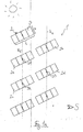
- FIG. 1 a shows a section of a solar system 1 according to the invention in the morning.
- the solar system 1 has a plurality of modular units 2, which each have four solar modules 3.
- the modular units 2 have a rectangular shape.
- the modular units 2 are placed with a slope to the ground and close with the ground an angle of about 38 °.
- the module units are positioned so that their solar modules face the sun. This arrangement is in the FIGS. 1a-f not recognizable. This is on the FIG. 2 directed.
- the module units 2 are individually trackable to the sun.
- each module unit 2 is assigned a tracking device. These individual tracking devices can, for example, by means of a motor, put the module units 2 in a rotational movement and thus track the sun.
- These NachS. 1a-f can be coupled together, so that a coordinated tracking movement of the individual module units is possible.
- the modular units 2 have a ratio of width b to length 1 of about 1: 3.
- the modular units 2 are arranged in a plurality of substantially parallel rows (in the present case, only two such rows R 1 and R 2 are shown).
- the individual rows R (dashed lines in the figures) are each defined by a straight line on which the centers or pivot points of the individual module units 2 lie.
- the individual module units 2 of two adjacent rows R are staggered, in such a way that the centers of two adjacent module units 2 of a row with a center of a module unit of an adjacent row form a substantially isosceles triangle.
- To form in the FIG. 1a the centers D1 and D2 of the row R 1 with the center D3 of the series R 2 an isosceles triangle.
- the length of a module unit 2 is about 20% less than the distance between the centers of two adjacent modular units 2 of a row. As a result, touching the individual rows of modules during the tracking movement is prevented.
- the distance between the centers of two adjacent module units 2 of one row approximately corresponds to the distance between two adjacent rows.
- the modular units 2 of two adjacent rows in turn form parallel rows of juxtaposed rows of modules.
- the module units 2a and 2b, together with other module units, not shown here form a module unit row.
- Parallel to this row of modular units is a row of modular units parallel to this row consisting of module units 2c and 2d.
- the individual module units of a modular unit row are arranged at a small distance from each other, which is sufficient, however, that the module units do not touch during the rotary movement.
- FIG. 1b shows Solaranlade 1 in the early morning.
- the individual module units 2 are now arranged such that they form parallel modular unit rows with further module units, not shown here, of further rows.
- the distance of the modular units 2 within such modular unit rows is greater at this position than at the position in FIG. 1a , wherein this distance is greater than the length of the individual module units 2 .:
- Both in the position of FIG. 1 a as well as in the FIG. 1b is the distance between the successive module units (eg module unit 2a and module unit 2c) is so large that a mutual shading as good as not takes place.
- FIG. 3c shows the solar system 1 in comparison to FIG. 1b about one to two hours later.
- new rows of modular units 2 have again formed.
- the module units 2a and 2d (together with other module units, not shown here) now form a module unit row.
- Figure 1d shows the solar system 1 after compared to Figure 1c again a certain time has elapsed (late morning).
- module units 2e and 2b now lie in a module unit row.
- the modular units eg module unit 2b and 2a or 2d and 2c
- arranged immediately one behind the other are again far enough apart to prevent mutual shading.
- the Figure 1e shows the solar system 1 at lunchtime.
- the modular units 2 of a row eg R 1 or R 2
- the module units 2a and 2c or 2b and 2d each lie in a modular unit row.
- FIG. 1f shows the solar system 1 already in the evening hours. Order from the arrangement in FIG. 1a (Morning sun) to the arrangement in FIG. 1f (Evening sun), a tracking of the modular units 2 of over 200 ° was required. Between the arrangement in Figure 1e and the arrangement in FIG. 1f is half a day. Within this half day, it has of course come to further modular unit series - formations. When arranged in FIG. 1f For example, module units 2e and 2b and 2a and 2d now form modular unit rows.
- the modular units of FIGS. 1a to 1f preferably have a length of 4.5 m and a width of 1.6 m.
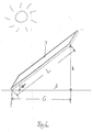
- FIG. 2 shows a solar module 3 of a module unit 2.
- the solar module 3 is arranged at a certain angle. This angle of attack in the present case is 38 °. By the angle of attack results over the length L of the solar module 4, a corresponding height h starting from a horizontal base line Z.
- the length of the base area under the solar module 3 in the plan view is denoted by G. From the length L of the solar module and the angle of attack results in the so-called shading factor.
- This shading factor corresponds to the distance between two successive solar modules or module units, the is to be observed in order to avoid just a mutual shading. This shading factor is regionally different.
- the height h of the solar module must be multiplied by the shading factor and the basic length G added to the result. If the height h corresponds, for example, to 1 m and the shading factor is 4 m and the basic length G is 1.3 m, for example, the distance between two rows (eg R 1 and R 2 ) is 5.3 m. This distance ensures that the modular element rows forming in the course of the day (not to be confused with the rows of pivot points, eg R 1 and R 2 ) do not mutually shadow each other.
Landscapes
- Engineering & Computer Science (AREA)
- Architecture (AREA)
- Civil Engineering (AREA)
- Structural Engineering (AREA)
- Physics & Mathematics (AREA)
- Life Sciences & Earth Sciences (AREA)
- Sustainable Development (AREA)
- Sustainable Energy (AREA)
- Thermal Sciences (AREA)
- Chemical & Material Sciences (AREA)
- Combustion & Propulsion (AREA)
- Mechanical Engineering (AREA)
- General Engineering & Computer Science (AREA)
- Photovoltaic Devices (AREA)
Applications Claiming Priority (1)
| Application Number | Priority Date | Filing Date | Title |
|---|---|---|---|
| DE102007014913A DE102007014913A1 (de) | 2007-03-26 | 2007-03-26 | Solaranlage |
Publications (2)
| Publication Number | Publication Date |
|---|---|
| EP1978313A2 true EP1978313A2 (fr) | 2008-10-08 |
| EP1978313A3 EP1978313A3 (fr) | 2012-08-15 |
Family
ID=39627744
Family Applications (1)
| Application Number | Title | Priority Date | Filing Date |
|---|---|---|---|
| EP08005376A Withdrawn EP1978313A3 (fr) | 2007-03-26 | 2008-03-20 | Installation solaire |
Country Status (3)
| Country | Link |
|---|---|
| US (1) | US20080236570A1 (fr) |
| EP (1) | EP1978313A3 (fr) |
| DE (1) | DE102007014913A1 (fr) |
Families Citing this family (6)
| Publication number | Priority date | Publication date | Assignee | Title |
|---|---|---|---|---|
| DE102008051069A1 (de) * | 2008-10-09 | 2010-04-15 | Kuebler, Hans, Dr. | Vorrichtung zur Nachführung von Solarpaneelen in Photovoltaikanlagen zur Stromgewinnung |
| RU2474927C1 (ru) * | 2011-08-02 | 2013-02-10 | Российская Федерация, От Имени Которой Выступает Министерство Промышленности И Торговли Российской Федерации | Конструкция системы концентраторных фотоэлектрических установок |
| US11283395B2 (en) | 2018-03-23 | 2022-03-22 | Nextracker Inc. | Multiple actuator system for solar tracker |
| US11387771B2 (en) | 2018-06-07 | 2022-07-12 | Nextracker Llc | Helical actuator system for solar tracker |
| US11050383B2 (en) | 2019-05-21 | 2021-06-29 | Nextracker Inc | Radial cam helix with 0 degree stow for solar tracker |
| WO2024009003A1 (fr) * | 2022-07-06 | 2024-01-11 | Trailander Oy | Système et procédé de production d'électricité au moyen de panneaux solaires |
Family Cites Families (19)
| Publication number | Priority date | Publication date | Assignee | Title |
|---|---|---|---|---|
| US1111239A (en) * | 1914-04-16 | 1914-09-22 | Henry D Smelser | Device for concentrating the rays of the sun. |
| US4117682A (en) * | 1976-11-01 | 1978-10-03 | Smith Otto J M | Solar collector system |
| US4429178A (en) * | 1981-07-13 | 1984-01-31 | Acurex Solar Corporation | Solar tracking apparatus utilizing photovoltaic flat panels and method |
| US4466423A (en) * | 1982-09-30 | 1984-08-21 | The United States Of America As Represented By The United States Department Of Energy | Rim-drive cable-aligned heliostat collector system |
| FR2643510B1 (fr) * | 1989-02-23 | 1994-02-25 | Gallois Montbrun Roger | Capteur solaire perfectionne |
| US5169456A (en) * | 1991-10-22 | 1992-12-08 | Johnson Kenneth C | Two-axis tracking solar collector mechanism |
| WO2001055651A1 (fr) * | 2000-01-27 | 2001-08-02 | Haber Michael B | Mecanisme d'inclinaison de panneaux solaires |
| JP2003324210A (ja) * | 2002-04-30 | 2003-11-14 | Yoshitaka Karasawa | パネル分割型、太陽追尾式ソーラーパネルシステム |
| ES2326121T3 (es) * | 2003-03-18 | 2009-10-01 | Sunpower Corporation, Systems | Dispositivo colector solar orientable. |
| DE20305124U1 (de) * | 2003-03-30 | 2003-07-24 | PROZOP Solar GmbH, 97299 Zell | Gerät zur Sonnennachführung von Solarenergieanlagen |
| WO2005028969A1 (fr) * | 2003-09-22 | 2005-03-31 | Elettropiemme Snc Di Pegoretti Marcello & C. | Dispositif capteur d'energie solaire servant a absorber d'energie solaire et a la convertir en energie electrique |
| DE102004018151A1 (de) * | 2004-04-08 | 2005-10-27 | Neff, Siegfried | Vorrichtung zur Ausrichtung eines Solarmoduls |
| DE202005002411U1 (de) * | 2005-02-14 | 2005-04-21 | A & F Stahl- Und Maschinenbau Gmbh | Gestell zur Lagerung von Solarmodulen |
| DE102005014320A1 (de) * | 2005-03-30 | 2006-10-12 | Gümpelein, Manuela | Nachführeinrichtung für eine Photovoltaikanlage |
| WO2006130892A1 (fr) * | 2005-06-06 | 2006-12-14 | Innova Patent Gmbh | Installation de production d'energie electrique |
| US7252083B2 (en) * | 2005-07-18 | 2007-08-07 | Arizona Public Service Company | Structure for supporting energy conversion modules and solar energy collection system |
| DE102005055258B4 (de) * | 2005-11-19 | 2009-12-24 | Goldbeck Solar Gmbh | Verfahren zur Steuerung einer Montierung für eine Gruppe von Solarmodulen |
| DE202006015917U1 (de) * | 2005-11-30 | 2007-01-04 | Nießing Anlagenbau GmbH | Solaranlage |
| US7714260B2 (en) * | 2007-03-30 | 2010-05-11 | Hamilton Sundstrand Corporation | Stackable heliostat frame structure |
-
2007
- 2007-03-26 DE DE102007014913A patent/DE102007014913A1/de not_active Withdrawn
-
2008
- 2008-03-20 EP EP08005376A patent/EP1978313A3/fr not_active Withdrawn
- 2008-03-25 US US12/054,923 patent/US20080236570A1/en not_active Abandoned
Also Published As
| Publication number | Publication date |
|---|---|
| EP1978313A3 (fr) | 2012-08-15 |
| DE102007014913A1 (de) | 2008-10-02 |
| US20080236570A1 (en) | 2008-10-02 |
Similar Documents
| Publication | Publication Date | Title |
|---|---|---|
| EP1978313A2 (fr) | Installation solaire | |
| DE102009041308A1 (de) | Anordnung, Unterkonstruktion und Photovoltaikanlage | |
| DE102009042092A1 (de) | Solaranlage | |
| DE3643487A1 (de) | Anlage zur gewinnung elektrischer energie | |
| EP3026366A2 (fr) | Agencement de module solaire | |
| DE202012103108U1 (de) | Tragkonstruktion für Solarmodule | |
| DE202020104397U1 (de) | Photovoltaikanlage | |
| EP1788322A1 (fr) | Monture pour un groupe de modules solaires | |
| CH712121A1 (de) | Montageanordnung für plattenförmige Elemente und Solaranordnung mit einer solchen Montageanordnung. | |
| EP3803229A1 (fr) | Système de montage pour monter des modules photovoltaïques sur des toits, comprenant des pierres de ballast | |
| WO2014041000A2 (fr) | Héliostat de thermie solaire | |
| EP2522928B1 (fr) | Dispositif destiné au montage de constructions sur une surface plane ou une surface à faible inclinaison | |
| DE202023100298U1 (de) | Anordnung und Befestigungsadapter zum Anbringen von Solarmodulen an einer Haltekonstruktion, die auf einer landwirtschaftlichen Fläche errichtet ist | |
| EP1770340A2 (fr) | Dispositif pour la fixature et le pointage de collecteurs solaires | |
| DE102010041161B4 (de) | Solarmodulhalterungsvorrichtung | |
| DE202006009884U1 (de) | Unterkonstruktion für PV-Anlage | |
| DE102024100199A1 (de) | Zaun | |
| DE102010022645A1 (de) | Landwirtschaftliches Gebäude mit Fotovoltaik-Anlage | |
| DE102009051973A1 (de) | Modulträger; Traganordnung für eine Solaranlage; Solaranlage; Schablone zur Montage eines Modulträgers einer Tragkonstruktion für eine Solaranlage; Verfahren zur Montage eines Solarmoduls einer Solaranlage | |
| DE102023105252A1 (de) | Montagesystem und Tragkonstruktion zur Montage mindestens eines plattenförmigen Photovoltaik-Moduls und Solaranlage mit einer derartigen Tragkonstruktion | |
| EP2372268A2 (fr) | Dispositif de support pour éléments solaires | |
| DE202023105558U1 (de) | Agrar-Photovoltaik-Anordnung auf einer Freifläche | |
| EP1970643A1 (fr) | Dispositif et procédé destinés au suivi d'au moins un module d'une installation de module solaire | |
| EP4518146B1 (fr) | Dispositif de pulvérisation et de production d'énergie | |
| DE202010010793U1 (de) | Ständervorrichtung für vorzugsweise plattenförmige Solarmodule |
Legal Events
| Date | Code | Title | Description |
|---|---|---|---|
| PUAI | Public reference made under article 153(3) epc to a published international application that has entered the european phase |
Free format text: ORIGINAL CODE: 0009012 |
|
| AK | Designated contracting states |
Kind code of ref document: A2 Designated state(s): AT BE BG CH CY CZ DE DK EE ES FI FR GB GR HR HU IE IS IT LI LT LU LV MC MT NL NO PL PT RO SE SI SK TR |
|
| AX | Request for extension of the european patent |
Extension state: AL BA MK RS |
|
| PUAL | Search report despatched |
Free format text: ORIGINAL CODE: 0009013 |
|
| AK | Designated contracting states |
Kind code of ref document: A3 Designated state(s): AT BE BG CH CY CZ DE DK EE ES FI FR GB GR HR HU IE IS IT LI LT LU LV MC MT NL NO PL PT RO SE SI SK TR |
|
| AX | Request for extension of the european patent |
Extension state: AL BA MK RS |
|
| RIC1 | Information provided on ipc code assigned before grant |
Ipc: H01L 31/042 20060101ALI20120709BHEP Ipc: F24J 2/54 20060101AFI20120709BHEP |
|
| AKY | No designation fees paid | ||
| REG | Reference to a national code |
Ref country code: DE Ref legal event code: R108 |
|
| REG | Reference to a national code |
Ref country code: DE Ref legal event code: R108 Effective date: 20130424 |
|
| STAA | Information on the status of an ep patent application or granted ep patent |
Free format text: STATUS: THE APPLICATION IS DEEMED TO BE WITHDRAWN |
|
| 18D | Application deemed to be withdrawn |
Effective date: 20130216 |