EP1978329A1 - Procédé de mesure de la circularité de profilés ronds - Google Patents
Procédé de mesure de la circularité de profilés ronds Download PDFInfo
- Publication number
- EP1978329A1 EP1978329A1 EP07007089A EP07007089A EP1978329A1 EP 1978329 A1 EP1978329 A1 EP 1978329A1 EP 07007089 A EP07007089 A EP 07007089A EP 07007089 A EP07007089 A EP 07007089A EP 1978329 A1 EP1978329 A1 EP 1978329A1
- Authority
- EP
- European Patent Office
- Prior art keywords
- contour
- vectors
- center
- calculated
- determined
- Prior art date
- Legal status (The legal status is an assumption and is not a legal conclusion. Google has not performed a legal analysis and makes no representation as to the accuracy of the status listed.)
- Withdrawn
Links
- 238000000034 method Methods 0.000 title claims abstract description 35
- 239000013598 vector Substances 0.000 claims description 48
- 238000004088 simulation Methods 0.000 claims description 20
- 238000005259 measurement Methods 0.000 claims description 16
- 238000005096 rolling process Methods 0.000 claims description 9
- FGUUSXIOTUKUDN-IBGZPJMESA-N C1(=CC=CC=C1)N1C2=C(NC([C@H](C1)NC=1OC(=NN=1)C1=CC=CC=C1)=O)C=CC=C2 Chemical compound C1(=CC=CC=C1)N1C2=C(NC([C@H](C1)NC=1OC(=NN=1)C1=CC=CC=C1)=O)C=CC=C2 FGUUSXIOTUKUDN-IBGZPJMESA-N 0.000 claims description 4
- 238000009499 grossing Methods 0.000 claims description 3
- 239000000047 product Substances 0.000 description 11
- 238000004364 calculation method Methods 0.000 description 8
- 238000011156 evaluation Methods 0.000 description 4
- 239000007787 solid Substances 0.000 description 4
- 229910000831 Steel Inorganic materials 0.000 description 3
- 238000011326 mechanical measurement Methods 0.000 description 3
- 239000010959 steel Substances 0.000 description 3
- 238000001816 cooling Methods 0.000 description 2
- 238000004519 manufacturing process Methods 0.000 description 2
- 239000007795 chemical reaction product Substances 0.000 description 1
- 238000009434 installation Methods 0.000 description 1
- 238000000691 measurement method Methods 0.000 description 1
- 230000000737 periodic effect Effects 0.000 description 1
- 230000002093 peripheral effect Effects 0.000 description 1
Images





Classifications
-
- G—PHYSICS
- G01—MEASURING; TESTING
- G01B—MEASURING LENGTH, THICKNESS OR SIMILAR LINEAR DIMENSIONS; MEASURING ANGLES; MEASURING AREAS; MEASURING IRREGULARITIES OF SURFACES OR CONTOURS
- G01B11/00—Measuring arrangements characterised by the use of optical techniques
- G01B11/24—Measuring arrangements characterised by the use of optical techniques for measuring contours or curvatures
- G01B11/2408—Measuring arrangements characterised by the use of optical techniques for measuring contours or curvatures for measuring roundness
-
- G—PHYSICS
- G01—MEASURING; TESTING
- G01B—MEASURING LENGTH, THICKNESS OR SIMILAR LINEAR DIMENSIONS; MEASURING ANGLES; MEASURING AREAS; MEASURING IRREGULARITIES OF SURFACES OR CONTOURS
- G01B11/00—Measuring arrangements characterised by the use of optical techniques
- G01B11/24—Measuring arrangements characterised by the use of optical techniques for measuring contours or curvatures
- G01B11/245—Measuring arrangements characterised by the use of optical techniques for measuring contours or curvatures using a plurality of fixed, simultaneously operating transducers
-
- B—PERFORMING OPERATIONS; TRANSPORTING
- B21—MECHANICAL METAL-WORKING WITHOUT ESSENTIALLY REMOVING MATERIAL; PUNCHING METAL
- B21B—ROLLING OF METAL
- B21B38/00—Methods or devices for measuring, detecting or monitoring specially adapted for metal-rolling mills, e.g. position detection, inspection of the product
- B21B38/04—Methods or devices for measuring, detecting or monitoring specially adapted for metal-rolling mills, e.g. position detection, inspection of the product for measuring thickness, width, diameter or other transverse dimensions of the product
Definitions
- the invention relates to a method for roundness measurement or measurement of the shape deviation of in its longitudinal direction advanced round profiles in rolling mills, in per se known manner using a measuring device with at least two laser scanners, each having a photosensitive sensor and a laser, at least three on the generated to survey the round profile fitting and the round profile enclosing, forming a polygon shadow edges and measured and calculated from the corresponding tangents.
- long products are rolled in specialized rolling mills in order to obtain the desired end products. If these long products are to be rolled into round bars, then they are usually rolled in a 3-roll finishing stand with several roll blocks (usually a 3-roll block) to the final dimension and run on a cooling bed for cooling. Usually, four roller blocks with three roller discs are used, wherein the center planes of the roller discs are pivoted from one to the next roller block by 60 °.
- Such bar steel often has polygonal shape deviations from the circular shape. The predominant form is "three-wave” or "six-wave".
- non-contact measuring devices have also been known for decades.
- JP 56-117107 A a profile measuring method described in which the long product to be measured by means of laser beams is measured or scanned.
- this document describes, for example, that even with a uniform thickness a precise profile measurement is possible by applying first, second and third tangents to the outer circumference of an object whose profile is to be measured, and the difference between them Tangent specific circle and the profile of the long product to be measured whose profile measurement takes place.
- the application of the tangents is carried out with the help of laser beams or projection beams.
- the round product is illuminated by the laser beam from each of the laser scanners in such a way that the round product throws one or two shadow edges onto the associated sensor.
- a straight line running parallel to the laser beam is calculated.
- a circle is calculated from each of three determined degrees on which the straight lines lie as tangents. The calculation of the circle is repeated and the out-of-roundness is determined as the difference between the largest and smallest diameters of the circles.
- This non-roundness determination has the disadvantage that with very small angle errors, the measured values are strongly falsified. This is especially the case if the tangents do not come to lie exactly on the maximum or minimum of the circumferential profile. Moreover, the centers of the circles in the room are not fixed, with the result that, for example, in the case of asymmetrical shape deviations, the profile determined has a periodic symmetry of the number of tangents and arrangements and does not reflect the true profile character.
- the object of the present invention is to provide a method with which the profile and the runout can be determined as precisely as possible by means of a non-contact measuring device in the production line.
- At least three shadow edges adjoining the round profile to be measured are generated by means of a measuring device equipped with at least two laser scanners.
- These laser scanners each have a photosensitive sensor and a laser.
- Such a measuring device is known from the aforementioned JP 56-117107 A and also the DE 100 23 172 A known.
- the round profile to be measured must lie completely within the light field of both laser scanners so that the required (at least three) shadow edges are generated and measured with these laser scanners.
- a tangential to the round profile fitting straight line or a tangent is calculated.
- the angles of the straight lines to each other are known.
- the laser scanners are arranged or selected such that at least three shadow edges a polygon is generated.
- the round profile to be measured is then within the area defined by this polygon. In the case of three shadow edges, this is a triangular area.
- the method according to the invention is characterized, inter alia, by the fact that in step a) a center Z 0 is calibrated and fixed in the measuring field of the measuring device.
- the plane of the measuring field is expediently arranged perpendicular to the forward movement of the round profiles.
- the calibration of the measuring device and thus the determination of the center Z 0 in the measuring field must be performed only once, for example, during assembly of the measuring device and / or after installation in the rolling mill before the online measurement is made of round profiles in question here. However, it is recommended to check the calibration from time to time and to repeat it if necessary.
- step b) of the method according to the invention perpendiculars are determined from the center Z 0 to the tangents measured during the method, and the distance between the center Z 0 and the tangents is thereby calculated.
- step c From the data calculated in step b), the vertices of the polygon enclosing the round profile are calculated in step c), whereby a contour is determined.
- a reference circle is then placed in this contour in step d) of the method according to the invention.
- This reference circle can be defined in four different ways, namely:
- the reference circle is placed so that it represents the smallest possible circle that fits around the contour.
- the reference circle is placed so that it represents the largest possible circle that fits in the contour, or
- the reference circle is so placed with respect to the contour that this reference circle, together with another, concentric to the reference circle circle includes the contour with minimal difference in radius.
- the diameter of the reference circle is calculated in the method according to the invention in step e). From the position in space, the reference center Zp is calculated, which represents the center point of the reference circle.
- step f) of the method according to the invention at least two vectors from this reference center Z p to the contour are calculated by this reference center. From this data the runout is determined.
- a contour simulation is preferably calculated from the available data on the polygon.
- Such a contour simulation can be expressed as a numerical approximation with polygons as a continuous function (Weierstrass approximation theorem).
- the contour simulation is preferably carried out with the aid of an adapted spline interpolation. Such smoothing calculations are otherwise well known to those skilled in the art.
- This procedure makes it possible to subsequently apply all possible analyzes and measurement methods, taking into account the totality of the profile character.
- Another advantage of this contour simulation is the fact that it can be used for any number of laser scanners.
- the arrangement of these laser scanners and the angle division need not be even or regular, but can be selected as required.
- Important factors in this regard include, for example, the spatial conditions and the expected shape errors.
- these vectors are determined and calculated such that they represent the minimum distance R min and the maximum distance R max of Zp to the contour or contour simulation.
- step f) of the method according to the invention one or more sets of 2, 3 or more vectors (V GT1 , V GT2 and V GT3 or V DT1 , V DT2 and V DT3 ) extending from Zp to Contour contour or contour simulation.
- the vectors of a sentence in particular include the same angle between them, e.g. B. 60 ° or 120 °. In the case of 120 °, such a set thus consists of three vectors.
- the vectors of one set point from the reference center point Zp towards the nip of the last stand while the vectors of another set point from the reference center Zp towards the roll center of the last stand.
- the angle included by the vectors is preferably the same for all sets of vectors.
- the vectors of one set are preferably rotated relative to the vectors of the other sets.
- two sets of three vectors each can be calculated, with the vectors of each set including an angle of 120 °. If, for example, a vector of the first set of Zp points in the 0 ° direction (this reference direction must of course be specified) of the measuring field (more precisely the plane of the measuring field) up to the contour or contour simulation, then the two other vectors in 120 ° or 240 ° direction up to contour or contour simulation.
- the three vectors of the second set are twisted by 60 °, for example, so that from Zp in the 60 °, 180 ° and Show 300 ° direction. From this, the GT and DT values typical for 3-roll stands can be calculated without difficulty.
- the measuring device is rotated about the round profile, preferably in the form of an oscillating over 60 ° rotation ,
- the measurements are made at different times.
- the period of time which has elapsed between the individual measurements is determined. From this data, a motion vector for the round profile can be calculated so that it is possible to detect and compensate for the movement of the round profile.
- the measured data are computationally processed such that the measurements taken at intervals relate to the same reference center of the round profile.
- the measuring device is preferably not rotated.
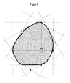
- FIG. 1 is a cross section through a to be measured round profile shown, the outer contour is shown with a solid, bold line.
- a total of six shadow edges are applied to this round profile with the aid of three laser scanners, which give rise to the tangents T 1 , T 2 , T 3 , T 4 , T 5 and T 6 as well as T 1 ' , T 2' , T 3 ' , T 4 ' , T 5 , and T 6 , lead.
- Tangent pairs T 1 , T 1 ' belong here; T 2 , T 2 ' ; T 3 , T 3 ' ; T 4 , T 4 ' ; T 5 , T 5 ' and T 6 , T 6' each to a laser scanner.
- six laser scanners are in use, whereby the round profile to be measured lies completely within the measuring field of these laser scanners.
- the center Z 0 of the measuring field of the measuring device was more accurately determined and calibrated prior to the application of the shadow edges or tangents.
- this number of tangents T can be arbitrary. However, at least three tangents are required to form a polygon enclosing the round profile. The tangents have a known angular position to each other.
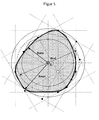
- FIG. 2 It is shown that the tangents obtained in the manner described above form a polygon enclosing the round profile with the corners A to L.
- the polygon is in the FIG. 2 shown with a bold, solid line, while the round profile is represented by a dotted line.
- FIG. 3 which form in the FIG. 2 shown polygon (in the FIG. 3 indicated by dotted line) Smoothing is obtained by means of a matched spline interpolation.
- usable data are obtained throughout the turn. In other words, data can also be determined for locations outside the values actually determined by the shadow edges or tangents.
- FIG. 4 is shown graphically how a reference circle (dot-dash line) is placed in the contour simulation (solid bold line) such that the square shape deviations of the contour simulation to this reference circle (dot-dash line) reaches a minimum.
- a reference circle whose diameter D ref is calculated.
- the reference center Zp is determined from the position of the reference circle in the room.
- the out-of-roundness are determined.
- the determined extreme values can be anywhere on the contour simulation. They can thus also lie in angular positions, which are located in sections of the contour between the original measuring points.
- step f) of the method according to the invention extending from the reference center Zp in the direction of the roll disks of the last two 3-roll stands of a rolling mill It is assumed that the center plane of the roller disks of the penultimate rolling stand are at 0 °, 120 ° and 240 ° and that of the last rolling stand at 60 °, 180 ° and 300 °. The 0 ° or 180 ° level lies in the FIG.
- the vectors V GT1 , V GT2 and V GT3 point to the gap between the roll disks of the last mill stand, while the vectors V DT1 , V DT2 and V DT3 point to the pressure point or to the roll center of the rolls of the last mill stand.
- this pressure point is located where the nip of the rolls of the penultimate roll stand is usually located.
- V GT1 , V GT2 and V GT3 can be calculated by simple mathematical calculations for the setting of rolling stands of interest here in question value GT, which is a measure of length.
- GT rolling stands of interest here in question value
- V DT1 , V DT2 and V DT3 from which the desired value DT, which also represents a length dimension, can be calculated.
- the measuring device required for the method according to the invention can not be arranged directly downstream of the last roll stand (for example for reasons of space) but only a certain distance downstream.
- the finished rolled round profile is twisted on the path from the last roll stand to the measuring plane of the measuring device, wherein the angle by which the round profile rotates about its longitudinal axis on this route, is usually known in the individual rolling trains.
- FIG. 7 is shown graphically how, despite the rotation of the round profile, the desired values GT and DT can be calculated. Because the twist angle that is in the FIG. 7 with ⁇ is known, the vectors described above are not in the direction of 0 °, 120 ° and 240 ° (applies to V GT1 , V GT2 and V GT3 ) and 60 °, 180 ° and 300 ° (applies to V DT1 , V DT2 and V DT3 ) from Zp to the contour simulation Hence like that in the FIG. 6 is shown. Rather, these vectors are also rotated by the twist angle ⁇ .
- the vectors V GT1 , V GT2 and V GT3 or V DT1 , V DT2 and V DT3 rotated by Zp by the angle ⁇ are calculated from Zp to the contour simulation (bold solid line).
- the vectors V GT1 , V GT2 and V GT3 are in the FIG. 7 each shown with an arrow with a solid line, while the vectors V DT1 , V DT2 and V DT3 are shown with an arrow with a dashed line.
- the typical values of GT and DT at the location of the last mill stand can also be determined by the same reference center Zp for arbitrary angular positions ⁇ taking into account all three vectors V GT1 , V GT2 and V GT3 or V DT1 , V DT2 and V DT3 . even if the measurement is performed only a certain distance after leaving the last mill stand.
- each vector of the vectors V GT1 , V GT2 and V GT3 or V DT1 , V DT2 and V DT3 can be determined individually, the absolute delivery of the individual rolls of the respective roll stands can be determined with the method according to the invention. If, for example, the pressure point of a roller of a 3-roller block is offset further radially inwards than the pressure points of the two other rollers, then this can be determined according to the invention. It must then be corrected only the radial position of only one roller.
Landscapes
- Physics & Mathematics (AREA)
- General Physics & Mathematics (AREA)
- Length Measuring Devices By Optical Means (AREA)
Priority Applications (9)
| Application Number | Priority Date | Filing Date | Title |
|---|---|---|---|
| EP07007089A EP1978329A1 (fr) | 2007-04-04 | 2007-04-04 | Procédé de mesure de la circularité de profilés ronds |
| CN2008800147704A CN101675316B (zh) | 2007-04-04 | 2008-04-01 | 用于进行圆型材的圆度测量的方法 |
| CH01548/09A CH698859B1 (de) | 2007-04-04 | 2008-04-01 | Verfahren zur Rundheitsmessung von Rundprofilen. |
| EP08748855A EP2132525B1 (fr) | 2007-04-04 | 2008-04-01 | Procédé de mesure de rotondité de profilés ronds |
| AT08748855T ATE547689T1 (de) | 2007-04-04 | 2008-04-01 | Verfahren zur rundheitsmessung von rundprofilen |
| US12/594,481 US8243284B2 (en) | 2007-04-04 | 2008-04-01 | Method for measuring the roundness of round profiles |
| CA2682635A CA2682635C (fr) | 2007-04-04 | 2008-04-01 | Methode de mesure de la rondeur de profils ronds |
| JP2010501423A JP5145409B2 (ja) | 2007-04-04 | 2008-04-01 | 丸線材の真円度を測定する方法 |
| PCT/EP2008/002593 WO2008122385A2 (fr) | 2007-04-04 | 2008-04-01 | Procédé de mesure de rotondité de profilés ronds |
Applications Claiming Priority (1)
| Application Number | Priority Date | Filing Date | Title |
|---|---|---|---|
| EP07007089A EP1978329A1 (fr) | 2007-04-04 | 2007-04-04 | Procédé de mesure de la circularité de profilés ronds |
Publications (1)
| Publication Number | Publication Date |
|---|---|
| EP1978329A1 true EP1978329A1 (fr) | 2008-10-08 |
Family
ID=39018175
Family Applications (2)
| Application Number | Title | Priority Date | Filing Date |
|---|---|---|---|
| EP07007089A Withdrawn EP1978329A1 (fr) | 2007-04-04 | 2007-04-04 | Procédé de mesure de la circularité de profilés ronds |
| EP08748855A Not-in-force EP2132525B1 (fr) | 2007-04-04 | 2008-04-01 | Procédé de mesure de rotondité de profilés ronds |
Family Applications After (1)
| Application Number | Title | Priority Date | Filing Date |
|---|---|---|---|
| EP08748855A Not-in-force EP2132525B1 (fr) | 2007-04-04 | 2008-04-01 | Procédé de mesure de rotondité de profilés ronds |
Country Status (8)
| Country | Link |
|---|---|
| US (1) | US8243284B2 (fr) |
| EP (2) | EP1978329A1 (fr) |
| JP (1) | JP5145409B2 (fr) |
| CN (1) | CN101675316B (fr) |
| AT (1) | ATE547689T1 (fr) |
| CA (1) | CA2682635C (fr) |
| CH (1) | CH698859B1 (fr) |
| WO (1) | WO2008122385A2 (fr) |
Cited By (6)
| Publication number | Priority date | Publication date | Assignee | Title |
|---|---|---|---|---|
| WO2010037865A1 (fr) * | 2008-10-02 | 2010-04-08 | Zumbach Electronic Ag | Procédé de détermination de paramètres de forme |
| EP2725320A1 (fr) * | 2012-10-26 | 2014-04-30 | Zumbach Electronic Ag | Procédé de détermination de l'angle de rotation d'un profilé rond en déplacement longitudinal dans un train de laminoir |
| CN106442230A (zh) * | 2016-10-11 | 2017-02-22 | 中国石油大学(华东) | 一种基于图像处理技术的压裂支撑剂圆度、球度检定方法 |
| WO2017157358A1 (fr) * | 2016-03-17 | 2017-09-21 | Hegenscheidt-Mfd Gmbh | Procédé de mesure et de calcul de paramètres géométriques des roues d'un essieu monté pour véhicules ferroviaires |
| EP3399275A1 (fr) * | 2017-05-04 | 2018-11-07 | MULTIVAC Sepp Haggenmüller SE & Co. KG | Détermination de la position et de l'orientation d'un objet acheminé |
| CN116148949A (zh) * | 2022-12-29 | 2023-05-23 | 成都天奥信息科技有限公司 | 一种计算台风路径风圈覆盖区域的方法及系统 |
Families Citing this family (29)
| Publication number | Priority date | Publication date | Assignee | Title |
|---|---|---|---|---|
| CN102102976B (zh) * | 2009-12-18 | 2013-04-24 | 西安威而信精密仪器有限公司 | 一种可测量复杂回转体零件表面轮廓的仪器 |
| GB2489495B (en) * | 2011-03-31 | 2013-03-06 | Rolls Royce Plc | Checking positional accuracy of features |
| US12260023B2 (en) | 2012-01-17 | 2025-03-25 | Ultrahaptics IP Two Limited | Systems and methods for machine control |
| US9070019B2 (en) * | 2012-01-17 | 2015-06-30 | Leap Motion, Inc. | Systems and methods for capturing motion in three-dimensional space |
| US11493998B2 (en) | 2012-01-17 | 2022-11-08 | Ultrahaptics IP Two Limited | Systems and methods for machine control |
| CN103033144B (zh) * | 2012-12-22 | 2016-05-18 | 上海市隧道工程轨道交通设计研究院 | 一种激光测圆装置及其应用方法 |
| WO2014200589A2 (fr) | 2013-03-15 | 2014-12-18 | Leap Motion, Inc. | Détermination d'informations de position pour un objet dans l'espace |
| EP2994251B1 (fr) | 2013-05-11 | 2017-08-23 | Zumbach Electronic Ag | Procédé de détermination de la qualité d'estampage d'un matériau en barre profilée |
| CN103383248B (zh) * | 2013-07-24 | 2016-09-14 | 丽水职业技术学院 | 一种关节轴承内圈外球面圆球度的检测方法 |
| CA2889281A1 (fr) * | 2013-09-30 | 2015-04-02 | Vysoka Skola Banska - Technicka Univerzita Ostrava | Procede de mesure sans contact des dimensions exterieures de sections transversales d'un materiau en tige de metallurgie et cadre modulaire pour le mettre en uvre |
| EP2937155B1 (fr) * | 2014-04-11 | 2021-04-07 | SMS group GmbH | Machine à laminer des bagues et procédé de commande d'une machine à laminer des bagues |
| CN107664483B (zh) * | 2016-07-29 | 2019-06-25 | 宝山钢铁股份有限公司 | 一种圆柱棒材形状参数测量方法 |
| CN107561106B (zh) * | 2017-08-31 | 2020-06-05 | 长江存储科技有限责任公司 | 一种条痕状形貌表征参数的测量方法及装置 |
| CN107716563B (zh) * | 2017-09-26 | 2019-02-26 | 西安理工大学 | 基于红外光的带材自动对中检测方法 |
| CN108581239B (zh) * | 2018-04-10 | 2020-03-20 | 上海柏楚电子科技股份有限公司 | 一种用于方管激光切割测定偏移和实时刀路补偿的方法 |
| CN108868742B (zh) * | 2018-06-08 | 2022-03-29 | 中国石油天然气股份有限公司 | 确定管类井下落物的来源的方法、装置及存储介质 |
| DE102018119736B4 (de) * | 2018-08-14 | 2020-10-29 | Lap Gmbh Laser Applikationen | Verfahren zur Bestimmung der Position eines Walzspalts |
| CN109341577B (zh) * | 2018-10-19 | 2020-06-12 | 北京市机械施工有限公司 | 一种钢管加工椭圆度检测装置 |
| CN111310106B (zh) * | 2020-01-19 | 2024-02-06 | 浙江工业大学 | 一种基于逐步逼近原始轮廓的切割轮廓拟合优化方法 |
| CN111578866B (zh) * | 2020-06-16 | 2021-04-20 | 大连理工大学 | 一种多线激光传感器组合测量的空间位姿标定方法 |
| US11933863B2 (en) | 2020-07-27 | 2024-03-19 | Changxin Memory Technologies, Inc. | Method for measuring shortest distance between capacitances and method for evaluating capacitance manufacture procedure |
| CN114001692B (zh) * | 2020-07-27 | 2023-04-07 | 长鑫存储技术有限公司 | 测量电容之间最短距离的方法及评价电容制程的方法 |
| CN112025339B (zh) * | 2020-08-28 | 2021-12-14 | 中钢集团西安重机有限公司 | 一种确定回转罐体中心孔位置的方法 |
| CN116802570A (zh) * | 2021-02-01 | 2023-09-22 | 发那科株式会社 | 数值控制装置 |
| CN113639662A (zh) * | 2021-08-25 | 2021-11-12 | 上海米度测量技术有限公司 | 一种管环圆度测量装置及方法 |
| CN114018202B (zh) * | 2021-11-08 | 2024-02-02 | 绍兴职业技术学院 | 一种快速评定圆度的新算法 |
| CN113820720B (zh) * | 2021-11-22 | 2022-01-25 | 成都星宇融科电力电子股份有限公司 | 基于多参考基点的三维激光中心测距方法、系统及终端 |
| CN115047488B (zh) * | 2022-06-13 | 2025-05-27 | 南京工程学院 | 一种结合区域信息和角点检测算子的线性特征拟合方法 |
| CN115127425B (zh) * | 2022-06-29 | 2024-09-20 | 北京航天控制仪器研究所 | 一种轴孔类零件三点找正修圆方法 |
Citations (4)
| Publication number | Priority date | Publication date | Assignee | Title |
|---|---|---|---|---|
| JPS56117107A (en) * | 1980-02-20 | 1981-09-14 | Sumitomo Metal Ind Ltd | Measuring method of profile |
| DE3916715A1 (de) * | 1988-10-04 | 1990-04-05 | Thaelmann Schwermaschbau Veb | Verfahren zur walzspaltregelung der fertigstaffel |
| DE4037383A1 (de) * | 1990-11-20 | 1992-05-21 | Mesacon Messtechnik | Verfahren zum kontinuierlichen beruehrungsfreien messen von profilen und einrichtung zur durchfuehrung des messverfahrens |
| DE10023172A1 (de) * | 2000-05-11 | 2001-11-22 | Laser Applikationan Gmbh | Vorrichtung und Verfahren zur Messung der Dicke und Unrundheit von länglichen Werkstücken |
Family Cites Families (4)
| Publication number | Priority date | Publication date | Assignee | Title |
|---|---|---|---|---|
| JPS63205504A (ja) * | 1987-02-20 | 1988-08-25 | Sumitomo Metal Ind Ltd | プロフイ−ル測定方法 |
| JPH08145636A (ja) * | 1994-11-22 | 1996-06-07 | Sumitomo Metal Ind Ltd | 外径測定機を用いた形状測定方法 |
| JP2001041738A (ja) * | 1999-08-04 | 2001-02-16 | Tokyo Seimitsu Co Ltd | 真円度測定方法および装置 |
| CN1884965A (zh) * | 2005-06-24 | 2006-12-27 | 鸿富锦精密工业(深圳)有限公司 | 圆度测量系统及方法 |
-
2007
- 2007-04-04 EP EP07007089A patent/EP1978329A1/fr not_active Withdrawn
-
2008
- 2008-04-01 AT AT08748855T patent/ATE547689T1/de active
- 2008-04-01 CA CA2682635A patent/CA2682635C/fr not_active Expired - Fee Related
- 2008-04-01 JP JP2010501423A patent/JP5145409B2/ja not_active Expired - Fee Related
- 2008-04-01 US US12/594,481 patent/US8243284B2/en not_active Expired - Fee Related
- 2008-04-01 WO PCT/EP2008/002593 patent/WO2008122385A2/fr not_active Ceased
- 2008-04-01 EP EP08748855A patent/EP2132525B1/fr not_active Not-in-force
- 2008-04-01 CN CN2008800147704A patent/CN101675316B/zh not_active Expired - Fee Related
- 2008-04-01 CH CH01548/09A patent/CH698859B1/de not_active IP Right Cessation
Patent Citations (4)
| Publication number | Priority date | Publication date | Assignee | Title |
|---|---|---|---|---|
| JPS56117107A (en) * | 1980-02-20 | 1981-09-14 | Sumitomo Metal Ind Ltd | Measuring method of profile |
| DE3916715A1 (de) * | 1988-10-04 | 1990-04-05 | Thaelmann Schwermaschbau Veb | Verfahren zur walzspaltregelung der fertigstaffel |
| DE4037383A1 (de) * | 1990-11-20 | 1992-05-21 | Mesacon Messtechnik | Verfahren zum kontinuierlichen beruehrungsfreien messen von profilen und einrichtung zur durchfuehrung des messverfahrens |
| DE10023172A1 (de) * | 2000-05-11 | 2001-11-22 | Laser Applikationan Gmbh | Vorrichtung und Verfahren zur Messung der Dicke und Unrundheit von länglichen Werkstücken |
Non-Patent Citations (1)
| Title |
|---|
| WAGNER M ET AL: "SCHNELLE ON-LINE-DURCHMESSER- UND RUNDHEITSPRUFUNG MIT LASERMESSSYSTEMEN IN EINER DRAHTWALZSTRASSE", STAHL UND EISEN, VERLAG STAHLEISEN, DUSSELDORF, DE, vol. 114, no. 12, 15 December 1994 (1994-12-15), pages 99 - 101, XP000481027, ISSN: 0340-4803 * |
Cited By (7)
| Publication number | Priority date | Publication date | Assignee | Title |
|---|---|---|---|---|
| WO2010037865A1 (fr) * | 2008-10-02 | 2010-04-08 | Zumbach Electronic Ag | Procédé de détermination de paramètres de forme |
| EP2725320A1 (fr) * | 2012-10-26 | 2014-04-30 | Zumbach Electronic Ag | Procédé de détermination de l'angle de rotation d'un profilé rond en déplacement longitudinal dans un train de laminoir |
| WO2017157358A1 (fr) * | 2016-03-17 | 2017-09-21 | Hegenscheidt-Mfd Gmbh | Procédé de mesure et de calcul de paramètres géométriques des roues d'un essieu monté pour véhicules ferroviaires |
| US10859470B2 (en) | 2016-03-17 | 2020-12-08 | Hegenscheidt-Mfd Gmbh & Co. Kg | Method for measuring and calculating geometric parameters of the wheels of a wheelset for rail vehicles |
| CN106442230A (zh) * | 2016-10-11 | 2017-02-22 | 中国石油大学(华东) | 一种基于图像处理技术的压裂支撑剂圆度、球度检定方法 |
| EP3399275A1 (fr) * | 2017-05-04 | 2018-11-07 | MULTIVAC Sepp Haggenmüller SE & Co. KG | Détermination de la position et de l'orientation d'un objet acheminé |
| CN116148949A (zh) * | 2022-12-29 | 2023-05-23 | 成都天奥信息科技有限公司 | 一种计算台风路径风圈覆盖区域的方法及系统 |
Also Published As
| Publication number | Publication date |
|---|---|
| CH698859B1 (de) | 2011-04-15 |
| JP5145409B2 (ja) | 2013-02-20 |
| CA2682635A1 (fr) | 2008-10-16 |
| EP2132525B1 (fr) | 2012-02-29 |
| US8243284B2 (en) | 2012-08-14 |
| ATE547689T1 (de) | 2012-03-15 |
| CN101675316A (zh) | 2010-03-17 |
| CA2682635C (fr) | 2014-12-09 |
| EP2132525A2 (fr) | 2009-12-16 |
| US20100245843A1 (en) | 2010-09-30 |
| CN101675316B (zh) | 2012-07-25 |
| WO2008122385A2 (fr) | 2008-10-16 |
| JP2010523948A (ja) | 2010-07-15 |
| WO2008122385A3 (fr) | 2008-12-11 |
Similar Documents
| Publication | Publication Date | Title |
|---|---|---|
| EP2132525B1 (fr) | Procédé de mesure de rotondité de profilés ronds | |
| EP2338025B1 (fr) | Procédé de détermination de paramètres de forme | |
| EP1154226B2 (fr) | Procédé et dispositif pour mesurer l'épaisseur et l'excentricité d'objets longitudinaux | |
| DE19809790A1 (de) | Verfahren und Vorrichtung zur Ermittlung einer Drallstruktur in der Oberfläche eines feinbearbeiteten zylindrischen Werkstücks | |
| DE60201206T2 (de) | Verfahren zur Detektion von Defekten in der Ebene | |
| DE102011009660A1 (de) | Automatisierung Rohrformpresse | |
| EP2604352B1 (fr) | Procédé de surveillance du processus de fabrication de tubes en acier fabriqués à chaud | |
| DE102011000304A1 (de) | Kalibrierung von Laser-Lichtschnittsensoren bei gleichzeitiger Messung | |
| DE3125009A1 (de) | Rohrwanddickenmessung | |
| DE102014203422B3 (de) | Verfahren und Computerprogramm zum Analysieren der Wanddickenverteilung eines Rohres | |
| DE3211489A1 (de) | Verfahren und vorrichtung zur korrektur von sollform-abweichungen platisch verformbarer gegenstaende | |
| WO2002033347A2 (fr) | Procede permettant de determiner l'alignement d'un corps cylindrique par rapport a une direction de reference | |
| DE102005009482B3 (de) | Verfahren und Vorrichtung zur Überwachung des Fertigungsprozesses zur Herstellung von warmgefertigten Rohren aus Stahl | |
| EP2725320B1 (fr) | Procédé de détermination de l'angle de rotation d'un profilé rond en déplacement longitudinal dans un train de laminoir | |
| DE19949834A1 (de) | Verfahren zum Ermitteln der Ausrichtung eines zylindrischen Körpers bezüglich einer Referenzrichtung | |
| EP0445899B1 (fr) | Méthode pour manufacture pour tubes sans couture avec épaisseurs moyennes et minces et dispositif de laminage d'exécution | |
| DE10349056A1 (de) | Verfahren und Vorrichtung zum Walzen von Walzgut in einer Walzanlage mit einem Schrägwalzwerk | |
| DE102011120816B4 (de) | Messverfahren zur Bestimmung eines geometrischen Istelements | |
| DE102016113717A1 (de) | Banddickenmessgerät und Verfahren zur Durchführung einer Banddickenmessung | |
| WO2019206958A1 (fr) | Laminoir à cylindres obliques à ajustement hydraulique des cylindres | |
| DE19758107A1 (de) | Mehrgerüstiges dornloses Streckreduzierwalzwerk | |
| EP1541250A1 (fr) | Procédé de positionnement axial de cylindres dans une cage de laminoir et cage de laminoir | |
| DE69800125T2 (de) | Methode zur Regelung der Rollen-Rotationsgeschwindigkeit beim Rollengiessverfahren | |
| WO2008131931A1 (fr) | Procédé et dispositif de mesure de la force de traction qui agit sur un tube mobile ou sur une barre mobile | |
| DE19722980C1 (de) | Verfahren und Vorrichtung zur Walzenkalibrierung eines Walzstranges zur Herstellung von runden Drähten |
Legal Events
| Date | Code | Title | Description |
|---|---|---|---|
| PUAI | Public reference made under article 153(3) epc to a published international application that has entered the european phase |
Free format text: ORIGINAL CODE: 0009012 |
|
| AK | Designated contracting states |
Kind code of ref document: A1 Designated state(s): AT BE BG CH CY CZ DE DK EE ES FI FR GB GR HU IE IS IT LI LT LU LV MC MT NL PL PT RO SE SI SK TR |
|
| AX | Request for extension of the european patent |
Extension state: AL BA HR MK RS |
|
| AKX | Designation fees paid | ||
| STAA | Information on the status of an ep patent application or granted ep patent |
Free format text: STATUS: THE APPLICATION IS DEEMED TO BE WITHDRAWN |
|
| 18D | Application deemed to be withdrawn |
Effective date: 20090409 |
|
| REG | Reference to a national code |
Ref country code: DE Ref legal event code: 8566 |