EP1978335A1 - Debitmetre - Google Patents
Debitmetre Download PDFInfo
- Publication number
- EP1978335A1 EP1978335A1 EP07707185A EP07707185A EP1978335A1 EP 1978335 A1 EP1978335 A1 EP 1978335A1 EP 07707185 A EP07707185 A EP 07707185A EP 07707185 A EP07707185 A EP 07707185A EP 1978335 A1 EP1978335 A1 EP 1978335A1
- Authority
- EP
- European Patent Office
- Prior art keywords
- flow rate
- fluid
- flow
- counter
- integrating
- Prior art date
- Legal status (The legal status is an assumption and is not a legal conclusion. Google has not performed a legal analysis and makes no representation as to the accuracy of the status listed.)
- Granted
Links
Images


Classifications
-
- G—PHYSICS
- G01—MEASURING; TESTING
- G01F—MEASURING VOLUME, VOLUME FLOW, MASS FLOW OR LIQUID LEVEL; METERING BY VOLUME
- G01F1/00—Measuring the volume flow or mass flow of fluid or fluent solid material wherein the fluid passes through a meter in a continuous flow
- G01F1/68—Measuring the volume flow or mass flow of fluid or fluent solid material wherein the fluid passes through a meter in a continuous flow by using thermal effects
- G01F1/684—Structural arrangements; Mounting of elements, e.g. in relation to fluid flow
- G01F1/6842—Structural arrangements; Mounting of elements, e.g. in relation to fluid flow with means for influencing the fluid flow
-
- G—PHYSICS
- G01—MEASURING; TESTING
- G01F—MEASURING VOLUME, VOLUME FLOW, MASS FLOW OR LIQUID LEVEL; METERING BY VOLUME
- G01F1/00—Measuring the volume flow or mass flow of fluid or fluent solid material wherein the fluid passes through a meter in a continuous flow
- G01F1/68—Measuring the volume flow or mass flow of fluid or fluent solid material wherein the fluid passes through a meter in a continuous flow by using thermal effects
-
- G—PHYSICS
- G01—MEASURING; TESTING
- G01F—MEASURING VOLUME, VOLUME FLOW, MASS FLOW OR LIQUID LEVEL; METERING BY VOLUME
- G01F1/00—Measuring the volume flow or mass flow of fluid or fluent solid material wherein the fluid passes through a meter in a continuous flow
-
- G—PHYSICS
- G01—MEASURING; TESTING
- G01F—MEASURING VOLUME, VOLUME FLOW, MASS FLOW OR LIQUID LEVEL; METERING BY VOLUME
- G01F1/00—Measuring the volume flow or mass flow of fluid or fluent solid material wherein the fluid passes through a meter in a continuous flow
- G01F1/68—Measuring the volume flow or mass flow of fluid or fluent solid material wherein the fluid passes through a meter in a continuous flow by using thermal effects
- G01F1/684—Structural arrangements; Mounting of elements, e.g. in relation to fluid flow
- G01F1/688—Structural arrangements; Mounting of elements, e.g. in relation to fluid flow using a particular type of heating, cooling or sensing element
- G01F1/69—Structural arrangements; Mounting of elements, e.g. in relation to fluid flow using a particular type of heating, cooling or sensing element of resistive type
- G01F1/692—Thin-film arrangements
-
- G—PHYSICS
- G01—MEASURING; TESTING
- G01F—MEASURING VOLUME, VOLUME FLOW, MASS FLOW OR LIQUID LEVEL; METERING BY VOLUME
- G01F1/00—Measuring the volume flow or mass flow of fluid or fluent solid material wherein the fluid passes through a meter in a continuous flow
- G01F1/68—Measuring the volume flow or mass flow of fluid or fluent solid material wherein the fluid passes through a meter in a continuous flow by using thermal effects
- G01F1/696—Circuits therefor, e.g. constant-current flow meters
-
- G—PHYSICS
- G01—MEASURING; TESTING
- G01F—MEASURING VOLUME, VOLUME FLOW, MASS FLOW OR LIQUID LEVEL; METERING BY VOLUME
- G01F1/00—Measuring the volume flow or mass flow of fluid or fluent solid material wherein the fluid passes through a meter in a continuous flow
- G01F1/72—Devices for measuring pulsing fluid flows
-
- G—PHYSICS
- G01—MEASURING; TESTING
- G01F—MEASURING VOLUME, VOLUME FLOW, MASS FLOW OR LIQUID LEVEL; METERING BY VOLUME
- G01F15/00—Details of, or accessories for, apparatus of groups G01F1/00 - G01F13/00 insofar as such details or appliances are not adapted to particular types of such apparatus
- G01F15/07—Integration to give total flow, e.g. using mechanically-operated integrating mechanism
- G01F15/075—Integration to give total flow, e.g. using mechanically-operated integrating mechanism using electrically-operated integrating means
-
- G—PHYSICS
- G01—MEASURING; TESTING
- G01F—MEASURING VOLUME, VOLUME FLOW, MASS FLOW OR LIQUID LEVEL; METERING BY VOLUME
- G01F7/00—Volume-flow measuring devices with two or more measuring ranges; Compound meters
Definitions
- the present invention relates to a flowmeter capable of preventing erroneous integration of measured flow rates from being caused by fluctuation of a fluid in its flowing direction.
- a flowmeter arranged in the supply path of a fluid (gas) for measuring the amount of supply of the fluid is generally so configured as to measure the instantaneous flow rate of the fluid by using a flow sensor and to integrate the measured flow rate.
- the integrated flow rate measured by the flowmeter is used as information on the basis of which the user is charged for the supply of the fluid, namely, for the amount of the fluid (gas) used.
- the flowmeter should be able to measure the fluid supply amount with accuracy.
- the fluid (gas) fluctuates even though the fluid is actually not in use. For example, after flowing regularly in one direction, the fluid (gas) slowly flows backward in the opposite direction. Such fluctuation of the fluid is caused by pressure imbalance between the opposite sides of the flowmeter due to conditions of use of the fluid (gas) in other supply systems, or by uneven distribution of temperature in the piping. Since the flowmeter merely integrates the instantaneous flow rate measured by the flow sensor, a problem arises in that the flow rate of the fluctuating fluid is repeatedly added up.
- check valves are provided on the opposite sides of the flowmeter, for example.
- the use of the valves makes the construction of the flowmeter complicated and also leads to increase in manufacturing cost.
- a proposal has been made that in a low flow rate region where fluctuation of the fluid takes place, the integration of measured flow rates should be suspended. Where the fluid is not fluctuating but just flowing at a very small rate, however, the flow rate of the fluid fails to be measured, entailing increase in measurement error.
- the present invention was created to solve the above problems, and an object thereof is to provide a flowmeter capable of measuring the flow rate of a fluid with ease and high accuracy and thus obtaining an accurate integrated flow rate without being influenced by fluctuation of the fluid attributable, for example, to pressure imbalance between the opposite sides of the flowmeter or uneven distribution of temperature in the piping.
- the present invention provides a flowmeter comprising:
- the determination means judges the fluid to be fluctuating when a backward flow of the fluid is detected from the smoothed flow rate, and judges the fluid to be flowing regularly if the smoothed flow rate keeps showing a forward flow of the fluid over a predetermined period, that is, if no backward flow is detected over the predetermined period. Also, the determination means may judge the fluid to be flowing regularly as soon as the smoothed flow rate shows a forward flow rate exceeding a preset threshold.
- the integrated flow rate of the auxiliary counter may be reset each time a backward flow of the fluid is detected from the smoothed flow rate.
- the flow sensor may be a thermal flow sensor which, for example, includes a pair of thermally sensitive resistance elements arranged on both sides of a heater element in a flowing direction of the fluid and obtains a mass flow rate and flowing direction of the fluid based on a difference between temperatures detected by the respective thermally sensitive resistance elements.
- the flow sensor to be used may be any flow sensor insofar as it can detect a backward flow of the fluid, and it is not essential that the flow sensor should have the ability (capacity) to measure the mass flow rate of the backward flow with high accuracy.
- the flowmeter configured as above, when a backward flow of the fluid is detected from the smoothed flow rate obtained by smoothing the instantaneous flow rate measured by the flow sensor, it is judged that the fluid is fluctuating. Before the fluctuation is detected, the fluid is judged to be flowing regularly in the forward direction, and the smoothed flow rate, derived by smoothing the instantaneous flow rate measured by the flow sensor, is integrated by the integrating counter. It is therefore possible to obtain an integrated flow rate with high accuracy corresponding to the flow rate detection accuracy of the flow sensor.
- the auxiliary counter When fluctuation of the fluid is detected, the auxiliary counter, instead of the integrating counter, integrates the smoothed flow rate. Then, when it is confirmed thereafter that regular flow has been recovered, the integrated flow rate held by the auxiliary counter is added to that held by the integrating counter, thus avoiding a situation where the flow rate of the forward flow recurring during the fluctuation of the fluid is repeatedly added up.
- the auxiliary counter integrates only the forward flow rate in such a manner that the integrated flow rate thereof is reset each time a backward flow of the fluid is detected, for example, and accordingly, the auxiliary counter eventually holds the integrated flow rate of the latest forward flow.
- the integrated flow rate held by the auxiliary counter is added to that held by the integrating counter, whereby an accurate flow rate of the forward flow that flowed during the fluctuation of the fluid can be added to the integrated flow rate held by the integrating counter.
- the auxiliary counter when a backward flow of the fluid is detected as fluctuation, the auxiliary counter starts integrating the forward flow rate of the fluctuating fluid, and if a backward flow is detected again while the fluid is fluctuating, the integrated flow rate held by the auxiliary counter is reset.
- the auxiliary counter holds the integrated flow rate of the latest forward flow only.
- a flowmeter according to one embodiment of the present invention will be hereinafter described with reference to the accompanying drawings, wherein a gas meter is taken as an example of the flowmeter.
- FIGS. 1 and 2 illustrate a schematic construction of a flowmeter (gas meter) according to the embodiment, wherein FIG. 1 is a partially sectional front view of the flowmeter, and FIG. 2 is a partially sectional side view of the flowmeter.
- the flowmeter includes a conduit unit 15 forming a flow channel for a fluid (gas).
- the conduit unit 15 has a pair of flanged joints 11 and 12 connected to piping (not shown) for conveying the fluid (gas), and a flow pipe 14 arranged between the flanged joints 11 and 12 and having a plurality of thermal type flow sensors 13 attached to a wall surface thereof.
- the conduit unit 15 has a cover 16 surrounding the flow pipe 14, and a box-shaped meter body 17 is mounted to the cover 16.
- the box-shaped meter body 17 contains an electronic circuit unit (not shown) comprising a microcomputer as its main component, for example.
- the electronic circuit unit obtains the flow rate of the fluid (gas) flowing in the conduit unit 15, on the basis of the outputs from the multiple thermal type flow sensors 13, and also integrates the measured flow rate to obtain an integrated flow rate.
- the meter body 17 has a front surface provided with an indicator 17a for displaying information such as the integrated flow rate obtained by the electronic circuit unit, a display mode switch 17b, etc.
- To respective opposite sides of the meter body 17 are attached a battery unit 17c as a source for driving the flowmeter, and a terminal box 17d connected with signal lines.
- the conduit unit 15 (flanged joint 11) has a filter 18 located at a fluid inlet side to prevent entry of extraneous matter into the flowmeter.
- Each thermal flow sensor 13 comprises, as shown in perspective and in section in FIGS. 3 and 4 , respectively, a thin diaphragm 13b formed on a substrate (silicon chip) 13a, a heat generating element (heater) 13h of platinum (Pt) or the like arranged on the diaphragm 13b, and a pair of temperature-sensitive resistance elements (temperature sensors) 13u and 13d also arranged on the diaphragm 13b and located on both sides of the heat generating element 13h in the flowing direction of the fluid.
- the thin diaphragm 13b extends over a concaved cavity 13c formed in the substrate (silicon chip) 13a, in a direction perpendicular to the flowing direction F of the fluid.
- the diaphragm 13b serves to properly position the heat generating element (heater) 13h and the temperature-sensitive resistance elements (temperature sensors) 13u and 13d in the flow of the fluid (gas).
- the thermal flow sensor 13 configured as above obtains a flow velocity (flow rate) of the fluid from a difference between the temperatures respectively measured, as resistance change, by the temperature-sensitive resistance elements (temperature sensors) 13u and 13d. Specifically, as heat is generated by the heat generating element (heater) 13h, distribution of temperature around the element 13h varies due to the fluid (gas) flowing along the sensor plane such that the temperature of the downstream side is higher than that of the upstream side, and the temperature distribution varies also depending on the flow velocity (flow rate) of the fluid. Making use of the facts, the thermal flow sensor 13 derives the flow velocity (flow rate) of the fluid from a difference between the temperatures measured by the respective temperature-sensitive resistance elements (temperature sensors) 13u and 13d.
- the flowing direction of the fluid is determined. Namely, if the temperature detected by the temperature-sensitive resistance element (temperature sensor) 13d is higher than that detected by the temperature-sensitive resistance element 13u, it is judged that the fluid is flowing in the forward direction. Conversely, if the temperature detected by the temperature-sensitive resistance element 13u is higher than that detected by the resistance element 13d, the fluid is judged to be flowing in the backward direction.
- the flowmeter is provided, as the thermal type flow sensors 13, with two flow sensors (high flow rate sensors) 13HA and 13HB for measuring the flow rate in a high flow rate region, and two flow sensors (low flow rate sensors) 13LA and 13LB for measuring the flow rate in a low flow rate region.
- the flow sensors 13HA, 13HB, 13LA and 13LB are attached to the wall surface of the flow pipe 14 such that each pair for measuring the flow rate in the same flow rate region diagonally face each other.
- the high flow rate sensors 13HA and 13HB are configured such that their heat generating elements (heaters) 13h generate a large amount of heat, compared with those of the low flow rate sensors 13LA and 13LB, whereby the flow rate measurement region can be expanded up to the high flow rate region, though the measurement accuracy in the low flow rate region is more or less sacrificed.
- the low flow rate sensors 13LA and 13LB are so configured as to exhibit high detection accuracy in the low flow rate region, compared with the high flow rate sensors 13HA and 13HB.
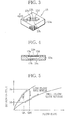
- These two types of flow sensors 13HA, 13HB; 13LA, 13LB are used to measure the flow rate of the fluid in such a manner that their flow rate measurements are hysteretically switched in accordance with the flow rate, for example, at two preset flow-rate thresholds QH and QL shown in FIG. 5 .
- the flowmeter according to the present invention comprises, as shown in FIG. 6 , an instantaneous flow rate measurement section 31 for measuring the instantaneous flow rate of the fluid from the outputs of the flow sensors 13, and an instantaneous flow rate smoother 32 for smoothing the measured instantaneous flow rate.
- the instantaneous flow rate smoother 32 removes disturbance components such as short-period pulsation attributable to the measurement intervals, shown in FIG. 7 , and backward flow of the fluid caused as a result of the reaction to the closing of fluid valves, and extracts only a long-duration variation component as a fluctuation component.
- this smoothing process is carried out by obtaining a moving average of instantaneous flow rates measured at the predetermined measurement intervals by the instantaneous flow rate measurement section 31.
- a fluctuation determination section 33 detects a backward flow component from the smoothed flow rate, thereby detecting fluctuation of the fluid. Also, after fluctuation of the fluid is detected, the fluctuation determination section 33 keeps monitoring the smoothed flow rate to detect recovery of regular flow by determining whether or not the fluid continues to flow forward over a preset period of time and also whether or not the detected flow rate shows a forward flow rate higher than or equal to a preset threshold. While the fluid flow detected by the flow sensors 13 is judged to be a regular flow, the fluctuation determination section 33 outputs the smoothed flow rate directly to an integrating counter 34, thus allowing the integrating counter 34 to obtain an integrated value (integrated flow rate) of the smoothed flow rate.
- the fluctuation determination section 33 stops outputting the smoothed flow rate to the integrating counter 34 and outputs the smoothed flow rate to an auxiliary counter 35 instead, to allow the auxiliary counter 35 to integrate the smoothed flow rate. Also, each time a backward flow of the fluid is detected, the fluctuation determination section 33 resets (clears) the auxiliary counter 35. On detecting recovery of regular flow, the fluctuation determination section 33 adds the integrated flow rate held by the auxiliary counter 35 to that held by the integrating counter 34 and then causes the integrating counter 34 to restart integrating the smoothed flow rate.
- the flowmeter of the present invention performs flow rate measurement. Specifically, when an instantaneous flow rate Qx is detected by the instantaneous flow rate measurement section 31 on the basis of the outputs of the flow sensors 13 (Step S1), the instantaneous flow rate smoother 32 smoothes the instantaneous flow rate Qx to remove short-duration variation components, thereby obtaining a flow rate variation component of long duration (Step S2).
- the fluctuation determination section 33 determines whether or not the smoothed flow rate Qx assumes a value equal to zero (0) or a positive value, thereby determining whether the fluid is flowing backward or not (Step S3). If no backward flow is detected, the fluctuation determination section 33 determines whether a regular flow flag F, which indicates that the fluid is flowing regularly, is set ON or not (Step S4). On confirming that the fluid is flowing regularly, the fluctuation determination section 33 allows the integrating counter 34 to integrate the flow rate Qx (Step S5).
- Step S3 the fluctuation determination section 33 judges that fluctuation of the fluid has occurred.
- the fluctuation determination section 33 clears a timer t, which is used to monitor the time for which the fluid continues to flow forward during the fluctuation, to zero (0) (Step S6), and also clears the auxiliary counter 35 to zero (0) (Step S7).
- the fluctuation determination section 33 turns off the regular flow flag F (Step S8) and waits for the instantaneous flow rate to be input at the next measurement timing.
- the fluctuation determination section 33 thereafter repeats the above process until the instantaneous flow rate Qx assumes zero (0) or a positive value.
- the fluctuation determination section 33 determines whether the flag F is set ON or not (Step S4). If the flag F is OFF and thus recovery of regular flow is not yet definitely established, the fluctuation determination section 33 makes a determination as to recovery of regular flow, on the assumption that the fluid is still fluctuating. The flow rate Qx detected at this time is added to the value in the auxiliary counter 35 (Step S9).
- the fluctuation determination section 33 determines whether or not the time measured by the timer t has reached a preset time ⁇ T, namely, whether or not the time for which the fluid (gas) has continued to flow forward is longer than or equal to the preset time ⁇ T (Step S10). If the forward flow continuance time is shorter than the preset time ⁇ T, the fluctuation determination section 33 determines whether or not the flow rate Qx shows a sudden increase exceeding a preset threshold TH (Step S11). By making these two determinations, recovery of regular flow from the fluctuation is determined.
- the auxiliary counter 35 adds up the small flow rate Qx (Step S9). Also, if a backward flow of the fluid is detected while the determination as to recovery of regular flow is being made, the fluctuation determination section 33 resets (clears) the integrated value of the auxiliary counter 35, as shown in FIG. 9 , and also clears the timer t (Steps S6 and S7). Accordingly, the flag F remains in the OFF state, and the aforementioned process is repeatedly executed so long as the flag F remains OFF. In this manner, the flow rate Qx detected while the fluid keeps flowing forward is added up by the auxiliary counter 35.
- Step S10 If, while the determination as to recovery of regular flow is being made, the forward flow continuance time is judged to have reached the preset time ⁇ T (Step S10) or the flow rate Qx is judged to be greater than the preset threshold TH (Step S11), the fluctuation determination section 33 concludes that the fluid is not fluctuating any longer and has recovered regular flow. In this case, the fluctuation determination section 33 sets the flag F to the ON state (Step S12).
- the fluctuation determination section 33 adds the integrated value Mx of the forward flow rate Qx, held by the auxiliary counter 35, to the integrated flow rate held by the integrating counter 34 (Step S13), whereby the forward flow rate detected during the determination as to recovery of regular flow (during the fluctuation) is added to the integrated flow rate of the integrating counter 34. Subsequently, the fluctuation determination section 33 causes the integrating counter 34 to restart integrating the currently measured flow rate Qx (Step S5), and the aforementioned process is repeatedly executed thereafter.
- the flowmeter of the present invention has the function whereby, while the fluid is fluctuating, the flow rate is added up using the auxiliary counter 35, and when regular flow is recovered, the integrated flow rate held by the auxiliary counter 35 is added to that held by the integrating counter 34 and the integrating counter 34 is restarted to integrate the flow rate Qx.
- the auxiliary counter 35 is used to integrate the flow rate of the fluid flowing forward during the fluctuation, and when the fluid is flowing regularly, the flow rate (smoothed flow rate) Qx detected by the flow sensors 13 is added up directly by the integrating counter 34. It is therefore possible to obtain the integrated flow rate with accuracy corresponding to the measurement accuracy of the flow sensors 13.
- the auxiliary counter 35 integrates the flow rate of a continuous forward flow in such a manner that each time a backward flow is detected, the auxiliary counter 35 is cleared. Accordingly, even in cases where fluctuation of the fluid is repeated, it is possible to always obtain the integrated flow rate of the latest forward flow. Namely, in the flowmeter of the present invention, when a backward flow occurs while the fluid is fluctuating, the flow rate integrated until then is cleared, whereby the backward flow is canceled out without fail and only the flow rate of the fluid flowing substantially in the forward direction can be measured.
- the integrated flow rate held by the auxiliary counter 35 is added to the integrated flow rate held by the integrating counter 34, and therefore, the flow rate of the fluid that flowed during the suspension of the flow rate integration by the integrating counter 34 can be added to the integrated flow rate of the integrating counter 34 without fail, as shown in FIG. 9 .
- the fluctuation determination section 33 detects such a flow as regular flow and causes the integrating counter 34 to restart the flow rate integration. Also, when the forward flow rate of the fluid suddenly increases, the fluctuation determination section 33 concludes that the sudden buildup of regular flow results from the start of supply of the fluid (gas), and causes the integrating counter 34 to restart the flow rate integration. Accordingly, the integrating counter 34 can quickly resume its normal flow rate integration. It is therefore possible to remove the influence of fluctuation caused by the closing of valves, without impairing the original function of the flowmeter.
- the present invention is not limited to the foregoing embodiment alone.
- the flowmeter is provided with the two high flow rate sensors 13HA and 13HB and the two low flow rate sensors 13LA and 13LB as in the above embodiment
- an average value of the outputs of the high flow rate sensors 13HA and 13HB or the low flow rate sensors 13LA and 13LB may be obtained as the instantaneous flow rate Qx. If, in this case, there is a large difference between the flow rates detected by the respective flow sensors 13LA, 13LB; 13HA, 13HB, the sensor outputs may be checked for deterioration and the reliable flow rate may be employed as the instantaneous flow rate Qx.
- the fluid may be regarded as flowing regularly, and only when the low flow rate sensors 13LA and 13LB are used to measure the flow rate, fluctuation of the fluid may be detected.
- the auxiliary counter 35 may be constituted by a reversible counter so that while the fluid is judged to be fluctuating, the forward and backward flow rates of the fluid may be counted up and down, respectively, by the reversible counter.
Landscapes
- Physics & Mathematics (AREA)
- Fluid Mechanics (AREA)
- General Physics & Mathematics (AREA)
- Measuring Volume Flow (AREA)
- Details Of Flowmeters (AREA)
Applications Claiming Priority (2)
| Application Number | Priority Date | Filing Date | Title |
|---|---|---|---|
| JP2006013626A JP4906357B2 (ja) | 2006-01-23 | 2006-01-23 | 流量計 |
| PCT/JP2007/050922 WO2007083799A1 (fr) | 2006-01-23 | 2007-01-22 | Debitmetre |
Publications (3)
| Publication Number | Publication Date |
|---|---|
| EP1978335A1 true EP1978335A1 (fr) | 2008-10-08 |
| EP1978335A4 EP1978335A4 (fr) | 2013-12-11 |
| EP1978335B1 EP1978335B1 (fr) | 2019-08-07 |
Family
ID=38287741
Family Applications (1)
| Application Number | Title | Priority Date | Filing Date |
|---|---|---|---|
| EP07707185.0A Ceased EP1978335B1 (fr) | 2006-01-23 | 2007-01-22 | Debitmetre |
Country Status (6)
| Country | Link |
|---|---|
| US (1) | US7861585B2 (fr) |
| EP (1) | EP1978335B1 (fr) |
| JP (1) | JP4906357B2 (fr) |
| KR (1) | KR100959519B1 (fr) |
| CN (1) | CN101371108B (fr) |
| WO (1) | WO2007083799A1 (fr) |
Cited By (2)
| Publication number | Priority date | Publication date | Assignee | Title |
|---|---|---|---|---|
| DE102008023654A1 (de) * | 2008-05-15 | 2009-11-19 | Endress + Hauser Flowtec Ag | Verfahren zur Bestimmung und/oder Überwachung des Durchflusses durch ein Messrohr |
| EP2345876A1 (fr) * | 2010-01-18 | 2011-07-20 | Flow-Tronic S.A. | Procédé pour éviter les sauts de mesures et améliorer la précision de débitmètres hybrides |
Families Citing this family (17)
| Publication number | Priority date | Publication date | Assignee | Title |
|---|---|---|---|---|
| JP5123231B2 (ja) * | 2009-03-10 | 2013-01-23 | アズビル株式会社 | 流量計、流量計測方法、及び流量計測プログラム |
| CN102781014A (zh) * | 2011-05-10 | 2012-11-14 | 淮阴工学院 | 基于无线传感器网络和3g网络的智能流量监测方法 |
| US8864643B2 (en) | 2011-10-13 | 2014-10-21 | Thoratec Corporation | Pump and method for mixed flow blood pumping |
| US9222812B2 (en) * | 2012-10-30 | 2015-12-29 | Itron, Inc. | Hybrid sensor system for gas flow measurements |
| US9170135B2 (en) | 2012-10-30 | 2015-10-27 | Itron, Inc. | Module for gas flow measurements with a dual sensing assembly |
| US9612146B2 (en) | 2014-02-07 | 2017-04-04 | Honeywell International, Inc. | Airflow sensor with dust reduction |
| US9976916B2 (en) * | 2014-04-14 | 2018-05-22 | National Research Council Of Canada | Air sensor with downstream facing ingress to prevent condensation |
| US9671254B2 (en) | 2014-09-18 | 2017-06-06 | Mueller International, Llc | Magnetic sensing to detect tampering with a utility meter |
| US9476740B2 (en) * | 2014-09-18 | 2016-10-25 | Mueller International, Llc | Reverse flow detection and annunciation |
| US9891088B2 (en) | 2014-09-18 | 2018-02-13 | Mueller International, Llc | Real-time flow compensation in usage accumulation |
| US9664550B2 (en) | 2014-09-18 | 2017-05-30 | Mueller International, Llc | Adjustable meter with tamper detection |
| US10094706B2 (en) | 2014-09-18 | 2018-10-09 | Mueller International, Llc | Mode activation using light detection |
| WO2017031714A1 (fr) * | 2015-08-26 | 2017-03-02 | 深圳市思达仪表有限公司 | Circuit d'échantillonnage, appareil de détection, instrument d'écoulement, et procédé de détection de signal d'écoulement |
| US9976871B2 (en) | 2015-11-30 | 2018-05-22 | Mueller International, Llc | Solid-state register initiated poll of status information |
| JP2021038930A (ja) * | 2019-08-30 | 2021-03-11 | オムロン株式会社 | ガスメータ |
| CN111397677A (zh) * | 2020-03-14 | 2020-07-10 | 浙江威星智能仪表股份有限公司 | 一种基于超声波计量的脉动流检测方法 |
| EP4198461B1 (fr) * | 2021-12-17 | 2025-10-01 | Honeywell International Inc. | Systèmes, procédés et appareils fournissant une élimination de bruit pour des composants de détection de débit |
Family Cites Families (14)
| Publication number | Priority date | Publication date | Assignee | Title |
|---|---|---|---|---|
| US3812330A (en) * | 1972-08-18 | 1974-05-21 | Dasibi Corp | Automatic calibration circuit for gas analyzers |
| US3889255A (en) * | 1974-03-22 | 1975-06-10 | Corning Glass Works | Digital calibration system for an electronic instrument |
| US3975727A (en) * | 1974-06-28 | 1976-08-17 | Technicon Instruments Corporation | Automated calibration and standardization apparatus |
| US4126040A (en) * | 1977-12-30 | 1978-11-21 | Gard, Inc. | Liquid level gauge |
| US4233989A (en) * | 1978-12-26 | 1980-11-18 | Rca Corporation | Echocardiographic apparatus for myocardial disease diagnosis by A-wave quantification |
| US4298948A (en) * | 1979-11-30 | 1981-11-03 | Ird Mechanalysis, Inc. | Method and apparatus for generating a digital representation of the instantaneous angular position of a rotating body and for generating rectangular coordinate equivalents thereof |
| DE3133182C1 (de) * | 1981-08-19 | 1983-01-13 | Mannesmann AG, 4000 Düsseldorf | Einrichtung zur Ermittlung des Metallbadspiegels in Schlacke-Metall-Baedern |
| JPS60150452A (ja) * | 1984-01-19 | 1985-08-08 | Mitsubishi Electric Corp | 内燃機関の燃料制御装置 |
| FR2572518B1 (fr) * | 1984-10-26 | 1988-07-08 | British Petroleum Co | Jaugeur pour citerne a liquide |
| DE3509118C2 (de) * | 1985-03-14 | 1994-03-24 | Bosch Gmbh Robert | Verfahren und Vorrichtung zur Messung des Durchsatzes eines ein Rohr durchströmenden Mediums |
| JP3141762B2 (ja) * | 1995-12-13 | 2001-03-05 | 株式会社日立製作所 | 空気流量計測装置及び空気流量計測方法 |
| JP2002081978A (ja) * | 2000-09-08 | 2002-03-22 | Kansai Gas Meter Co Ltd | 流量測定方法 |
| JP4269047B2 (ja) * | 2002-08-29 | 2009-05-27 | 東京瓦斯株式会社 | 積算流量計 |
| JP4269045B2 (ja) * | 2002-08-29 | 2009-05-27 | 東京瓦斯株式会社 | 積算流量計 |
-
2006
- 2006-01-23 JP JP2006013626A patent/JP4906357B2/ja not_active Expired - Lifetime
-
2007
- 2007-01-22 WO PCT/JP2007/050922 patent/WO2007083799A1/fr not_active Ceased
- 2007-01-22 US US12/087,959 patent/US7861585B2/en not_active Expired - Fee Related
- 2007-01-22 KR KR1020087012985A patent/KR100959519B1/ko not_active Expired - Fee Related
- 2007-01-22 EP EP07707185.0A patent/EP1978335B1/fr not_active Ceased
- 2007-01-22 CN CN2007800027515A patent/CN101371108B/zh not_active Expired - Fee Related
Cited By (3)
| Publication number | Priority date | Publication date | Assignee | Title |
|---|---|---|---|---|
| DE102008023654A1 (de) * | 2008-05-15 | 2009-11-19 | Endress + Hauser Flowtec Ag | Verfahren zur Bestimmung und/oder Überwachung des Durchflusses durch ein Messrohr |
| EP2345876A1 (fr) * | 2010-01-18 | 2011-07-20 | Flow-Tronic S.A. | Procédé pour éviter les sauts de mesures et améliorer la précision de débitmètres hybrides |
| US8855946B2 (en) | 2010-01-18 | 2014-10-07 | Flow-Tronic S.A. | Method for avoiding jump faulty measurements and improving accuracy in hybrid flow meters |
Also Published As
| Publication number | Publication date |
|---|---|
| US20100223992A1 (en) | 2010-09-09 |
| EP1978335B1 (fr) | 2019-08-07 |
| US7861585B2 (en) | 2011-01-04 |
| KR20080071161A (ko) | 2008-08-01 |
| JP2007192774A (ja) | 2007-08-02 |
| WO2007083799A1 (fr) | 2007-07-26 |
| EP1978335A4 (fr) | 2013-12-11 |
| JP4906357B2 (ja) | 2012-03-28 |
| CN101371108B (zh) | 2011-05-25 |
| CN101371108A (zh) | 2009-02-18 |
| KR100959519B1 (ko) | 2010-05-27 |
Similar Documents
| Publication | Publication Date | Title |
|---|---|---|
| US7861585B2 (en) | Flowmeter | |
| CN101506629B (zh) | 流量测量诊断 | |
| KR101717546B1 (ko) | 실시간으로 질량 유량 제어기를 통과하는 흐름을 모니터링하는 시스템 및 방법 | |
| CA2930519C (fr) | Dispositifs et methodes de mesure directe de tete de puits par effet coriolis | |
| CN106104402B (zh) | 提供压力不敏感自我验证的质量流量控制器的系统和方法 | |
| WO2004020958A1 (fr) | Debitmetre thermique | |
| JP2011232201A (ja) | 渦流量計の異常判定方法 | |
| JP2001296156A (ja) | 流量計測装置及び電子式流量メータ | |
| JP4832906B2 (ja) | 流量計 | |
| US20170307428A1 (en) | Thermal, Flow Measuring Device | |
| JP4623486B2 (ja) | 流量計測装置 | |
| JP2000074719A (ja) | 推量式流量計 | |
| JP3510378B2 (ja) | ガス流量計 | |
| JPH07333017A (ja) | 流量計 | |
| JP3856353B2 (ja) | ガスメータ | |
| JP4623488B2 (ja) | 流体の流れ計測装置 | |
| JP4623487B2 (ja) | 流量計測装置 | |
| JP2002062179A (ja) | ガスメータ | |
| JPH10293054A (ja) | 流量計 | |
| JP4426695B2 (ja) | 流量計測方法、流量計測装置及び電子式ガスメータ | |
| JP2008292287A (ja) | 流量計 | |
| JP2004354280A (ja) | 導圧管詰まり検出器およびそれを内蔵した差圧・圧力伝送器 | |
| JP2000009505A (ja) | フルイディック流量計 | |
| JP2004093173A (ja) | 積算流量計 | |
| JP2004093175A (ja) | 熱式流量計 |
Legal Events
| Date | Code | Title | Description |
|---|---|---|---|
| PUAI | Public reference made under article 153(3) epc to a published international application that has entered the european phase |
Free format text: ORIGINAL CODE: 0009012 |
|
| 17P | Request for examination filed |
Effective date: 20080723 |
|
| AK | Designated contracting states |
Kind code of ref document: A1 Designated state(s): DE FR GB |
|
| RBV | Designated contracting states (corrected) |
Designated state(s): DE FR GB IT |
|
| DAX | Request for extension of the european patent (deleted) | ||
| RBV | Designated contracting states (corrected) |
Designated state(s): DE FR GB IT |
|
| RAP1 | Party data changed (applicant data changed or rights of an application transferred) |
Owner name: AZBIL CORPORATION |
|
| A4 | Supplementary search report drawn up and despatched |
Effective date: 20131108 |
|
| RIC1 | Information provided on ipc code assigned before grant |
Ipc: G01F 15/075 20060101ALI20131104BHEP Ipc: G01F 1/684 20060101ALI20131104BHEP Ipc: G01F 1/68 20060101ALI20131104BHEP Ipc: G01F 1/696 20060101ALI20131104BHEP Ipc: G01F 1/692 20060101ALI20131104BHEP Ipc: G01F 7/00 20060101ALI20131104BHEP Ipc: G01F 1/00 20060101AFI20131104BHEP Ipc: G01F 1/72 20060101ALI20131104BHEP |
|
| 17Q | First examination report despatched |
Effective date: 20161021 |
|
| GRAP | Despatch of communication of intention to grant a patent |
Free format text: ORIGINAL CODE: EPIDOSNIGR1 |
|
| INTG | Intention to grant announced |
Effective date: 20180419 |
|
| GRAS | Grant fee paid |
Free format text: ORIGINAL CODE: EPIDOSNIGR3 |
|
| GRAA | (expected) grant |
Free format text: ORIGINAL CODE: 0009210 |
|
| AK | Designated contracting states |
Kind code of ref document: B1 Designated state(s): DE FR GB IT |
|
| REG | Reference to a national code |
Ref country code: GB Ref legal event code: FG4D |
|
| REG | Reference to a national code |
Ref country code: DE Ref legal event code: R096 Ref document number: 602007058973 Country of ref document: DE |
|
| REG | Reference to a national code |
Ref country code: DE Ref legal event code: R082 Ref document number: 602007058973 Country of ref document: DE Representative=s name: SCHIEBER FARAGO PATENTANWAELTE, DE |
|
| PGFP | Annual fee paid to national office [announced via postgrant information from national office to epo] |
Ref country code: FR Payment date: 20191216 Year of fee payment: 14 |
|
| PGFP | Annual fee paid to national office [announced via postgrant information from national office to epo] |
Ref country code: GB Payment date: 20200115 Year of fee payment: 14 Ref country code: DE Payment date: 20200107 Year of fee payment: 14 Ref country code: IT Payment date: 20200114 Year of fee payment: 14 |
|
| REG | Reference to a national code |
Ref country code: DE Ref legal event code: R097 Ref document number: 602007058973 Country of ref document: DE |
|
| PLBE | No opposition filed within time limit |
Free format text: ORIGINAL CODE: 0009261 |
|
| STAA | Information on the status of an ep patent application or granted ep patent |
Free format text: STATUS: NO OPPOSITION FILED WITHIN TIME LIMIT |
|
| 26N | No opposition filed |
Effective date: 20200603 |
|
| REG | Reference to a national code |
Ref country code: DE Ref legal event code: R119 Ref document number: 602007058973 Country of ref document: DE |
|
| GBPC | Gb: european patent ceased through non-payment of renewal fee |
Effective date: 20210122 |
|
| PG25 | Lapsed in a contracting state [announced via postgrant information from national office to epo] |
Ref country code: FR Free format text: LAPSE BECAUSE OF NON-PAYMENT OF DUE FEES Effective date: 20210131 |
|
| PG25 | Lapsed in a contracting state [announced via postgrant information from national office to epo] |
Ref country code: GB Free format text: LAPSE BECAUSE OF NON-PAYMENT OF DUE FEES Effective date: 20210122 Ref country code: DE Free format text: LAPSE BECAUSE OF NON-PAYMENT OF DUE FEES Effective date: 20210803 |
|
| PG25 | Lapsed in a contracting state [announced via postgrant information from national office to epo] |
Ref country code: IT Free format text: LAPSE BECAUSE OF NON-PAYMENT OF DUE FEES Effective date: 20210122 |