EP1978386A2 - Pièce d'accouplement pour une connexion enfichable - Google Patents
Pièce d'accouplement pour une connexion enfichable Download PDFInfo
- Publication number
- EP1978386A2 EP1978386A2 EP08102431A EP08102431A EP1978386A2 EP 1978386 A2 EP1978386 A2 EP 1978386A2 EP 08102431 A EP08102431 A EP 08102431A EP 08102431 A EP08102431 A EP 08102431A EP 1978386 A2 EP1978386 A2 EP 1978386A2
- Authority
- EP
- European Patent Office
- Prior art keywords
- coupling part
- coupling
- part according
- housing
- latching
- Prior art date
- Legal status (The legal status is an assumption and is not a legal conclusion. Google has not performed a legal analysis and makes no representation as to the accuracy of the status listed.)
- Withdrawn
Links
- 230000008878 coupling Effects 0.000 title claims description 106
- 238000010168 coupling process Methods 0.000 title claims description 106
- 238000005859 coupling reaction Methods 0.000 title claims description 106
- 238000006073 displacement reaction Methods 0.000 claims description 23
- 238000003780 insertion Methods 0.000 claims description 12
- 230000037431 insertion Effects 0.000 claims description 12
- 238000005452 bending Methods 0.000 claims description 5
- 230000001154 acute effect Effects 0.000 claims description 4
- 238000003825 pressing Methods 0.000 claims description 3
- 238000004080 punching Methods 0.000 claims description 3
- 239000000725 suspension Substances 0.000 claims description 2
- 230000003287 optical effect Effects 0.000 description 11
- 239000002184 metal Substances 0.000 description 3
- 230000000994 depressogenic effect Effects 0.000 description 2
- 238000004519 manufacturing process Methods 0.000 description 2
- 230000006835 compression Effects 0.000 description 1
- 238000007906 compression Methods 0.000 description 1
- 230000000694 effects Effects 0.000 description 1
Images
Classifications
-
- G—PHYSICS
- G02—OPTICS
- G02B—OPTICAL ELEMENTS, SYSTEMS OR APPARATUS
- G02B6/00—Light guides; Structural details of arrangements comprising light guides and other optical elements, e.g. couplings
- G02B6/24—Coupling light guides
- G02B6/36—Mechanical coupling means
- G02B6/38—Mechanical coupling means having fibre to fibre mating means
- G02B6/3807—Dismountable connectors, i.e. comprising plugs
- G02B6/3897—Connectors fixed to housings, casing, frames or circuit boards
-
- G—PHYSICS
- G02—OPTICS
- G02B—OPTICAL ELEMENTS, SYSTEMS OR APPARATUS
- G02B6/00—Light guides; Structural details of arrangements comprising light guides and other optical elements, e.g. couplings
- G02B6/24—Coupling light guides
- G02B6/36—Mechanical coupling means
- G02B6/38—Mechanical coupling means having fibre to fibre mating means
- G02B6/3807—Dismountable connectors, i.e. comprising plugs
- G02B6/381—Dismountable connectors, i.e. comprising plugs of the ferrule type, e.g. fibre ends embedded in ferrules, connecting a pair of fibres
- G02B6/3825—Dismountable connectors, i.e. comprising plugs of the ferrule type, e.g. fibre ends embedded in ferrules, connecting a pair of fibres with an intermediate part, e.g. adapter, receptacle, linking two plugs
Definitions
- the invention relates to a coupling part for a connector according to the preamble of claim 1.
- Such coupling parts are particularly suitable for optical connectors in which two optical connector parts can be connected to each other by means of a sleeve-like coupling housing.
- the coupling part itself is fastened to a front panel, for example a device wall.
- a coupling part for an optical connector for attaching to a vertical front panel or on a horizontal support plate is for example in the EP 974 854 A1 shown.
- the coupling part has a sleeve-like coupling housing, on the various brackets can be releasably attached.
- the brackets are one-piece bent parts made of metal. They can be designed as latching elements, whereby they can be used latching in corresponding rectangular openings of a front panel.
- resilient clamping straps are provided on two opposite sides of the locking element, which are clamped together with an abutment in the opening of the front panel. When inserting the coupling part in the opening, the outwardly angled clamping bracket are depressed until the abutment have reached the front panel.
- the clamps spring back outwards, whereby the latching connection is made.
- the clamps must first be depressed manually or by means of a tool, only then can the coupling part be pulled out of the opening.
- coupling parts of small dimensions which are commonly used for optical connectors, it has been found that the handling of these coupling parts can be difficult because of the small size of the clamp.
- the locking elements are resiliently and limitedly slidably supported on the clutch housing.
- the locking elements have a over the entire width of the coupling housing extending handle portion.
- a latching connection can be achieved with a front panel in a simple manner.
- On the coupling housing flanges are formed on two opposite sides, which form a stop for the front of the front panel. This flange also serves to hold each one locking element and forms a stop for limiting the displacement of a locking element away from the coupling housing.
- a disadvantage of this coupling part is its relatively large space requirement.
- the provided with a flange coupling housing can not be used for other purposes and can not be fixed with alternative fasteners on a circuit board, for example.
- the coupling part should allow a slim design.
- the coupling part should continue to be easy to manufacture and be characterized by easy handling when mounting and dismounting to a front panel.
- the coupling housing should also be suitable as a standard component for other purposes.
- a coupling part having the features in claim 1. Due to the fact that the latching element forms a stop for the front side of the front plate for fixing the inserted position, one can slim design can be achieved. In particular, flange portions projecting from the clutch housing do not need to be used to form a stop for the front panel.
- the locking element may be formed as a one-piece, separate bending part made of metal.
- Such coupling parts are particularly suitable for optical connectors of optical connector parts. Of course, but it would also be conceivable - instead of two connector parts to connect together - form the coupling housing as a receptacle, in which a plug-side connector inserted light on a fixed mounted optical element or receives light from this element.
- the suspension may be a leaf spring, which is integrally formed on the locking element.
- a spring means could for example be a helical compression spring, which is arranged between the handle portion and the clutch housing.
- two arm sections extending approximately plane-parallel along the coupling housing can adjoin the grip section.
- a preferably created by punching and bending operations spring tongue can be arranged as a leaf spring.
- Such an integrally formed locking element can be easily produced.
- the spring tongue is angled at an acute angle relative to the arm portions and extends in the insertion direction.
- the free end of the spring tongue can be directed against the front ends of the arm portions. Folding the spring tongue against the handle portion is not necessary.
- the spring tongue against the Handle portion is folded so far that it defines an acute angle to the handle portion.
- the latching element may be U-shaped in cross-section, wherein it has two leg portions which are interconnected by the transverse to this handle portion.
- the leg sections close approximately at right angles to the handle section.
- the latching element is snapped or snapped onto the coupling housing, wherein the leg sections are approximately vertical in the snapped position to the handle portion and inclined in rest position for generating a bias against a plane perpendicular to the handle portion extending inward.
- the locking element In the rest position is the locking element when it is not (yet) attached to the clutch housing.
- a survey which engages in a recess of a leg portion.
- the survey may protrude so far as a sliding surface on which slides the locking element in a sliding movement, insofar as its flat outer surface extends approximately flush with an adjacent outer side of the locking element.
- the depth of the survey can thus correspond approximately to the thickness of the locking element at least in the region of the handle sections.
- the elevation and the recess each have a rectangular shape in a plan view.
- Two rectangular sides of the survey can run in the direction of displacement, whereby an advantageous guide for the locking element can be reached.
- the other two sides of the rectangle, i. the transverse sides extending to the direction of the rectangle sides can each form a stop for limiting the displacement of the locking element.
- Another embodiment of the coupling part may be characterized in that two locking elements are provided, which are each resiliently supported on opposite side walls of the coupling housing and that on two opposite side walls of the coupling housing each have a survey is arranged and that each locking element has a leg portion with a recess , In each case engages an elevation in the corresponding recess for determining the displacement direction and / or for limiting the displacement.
- the locking connection with the front panel can be solved in a simple manner.
- Such an arrangement may also be advantageous for coupling parts of conventional design (i.e., a coupling part according to the preamble of claim 1).
- the sleeve-like coupling housing may be formed rectangular in cross section, wherein two opposing side walls may each be assigned to a handle portion of a locking element. At the side walls at right angles adjoining these side walls, the leg sections can be applied or abut.
- the two locking elements are identical is particularly advantageous.
- a kit to manufacture the coupling part substantially only two differently shaped components (a coupling part, two equal locking elements) is required.
- each locking element has a leg portion with a frame in which the recess is arranged and if in the opposite leg portion a guide arrangement is provided with two parallel guide portions between which the frame of each other locking element in the direction of displacement is limited displaced.
- the extending in the direction of displacement guide portions may have a (relative to the direction of displacement) front end, which may form a stop for the opposite other locking element.
- On the locking element may be arranged preferably extending approximately vertically to the side wall angle portion which may form a stop for the front of the front panel.
- Such angle sections can be produced in a simple manner by bending operations.
- the angle section is arranged on at least one leg section.
- such an angle section may be arranged on the front end of the front guide section relative to the insertion direction.
- the coupling part has two latching elements which are each arranged resiliently on opposite side walls, it may be advantageous if in each case only one leg section of a latching element has an angle section. The angle sections can then be used in the attachment of the Locking element on the coupling housing to be assigned to two opposite side walls of the coupling housing.
- the clutch housing may have an at least partially circumferential collar as a side boundary and guide for the at least one locking element. It may be particularly preferred if the coupling housing has two such at least partially circumferential collar. Each collar can serve as a side boundary and guide for each opposite direction of insertion. Particularly advantageously, the collar can be formed completely circumferentially.
- the collar may be formed by at least one end portion, wherein the acted upon by the locking elements areas of the side walls are offset from the end portion.
- the handle portion may be displaced in an end position by applying pressure far enough against the coupling housing, that the handle portion is flush or almost flush with the end portion.
- the latching element is by means of spring means, for example by means of molded leaf springs resiliently and limited displaceable on a housing of the module, in particular on the coupling housing supportable. It has at least one abutment which can be brought into engagement with a rear side of the front panel.
- an angle section can be formed on the locking element.
- the stop for the front side of the front panel by a rear edge of a recess comprising a pawl may be formed, wherein one of the rear side opposite edge of the recess, the abutment for the Back of the front panel can form.
- the pawl may be inserted in the inserted position in the opening of the front panel such that the flanks of the cutout for each side of the front panel form a stop.
- the front support of the pawl may be rounded. In this way, the locking element can be introduced during the latching operation in an advantageous manner in the opening of the front panel.
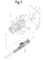
- FIG. 1 In the perspective view according to FIG. 1 is a designated coupling part 1, which can be used in the insertion direction e latching in an opening 4 of a front panel 5.
- the coupling part 1 has a sleeve-like coupling housing 2, with the help of two connector parts are connected to each other.
- an E-2000 plug is shown which can be inserted from two sides into the coupling housing 2.
- the coupling part 1 is particularly suitable for optical connectors, wherein as connector parts (30) corresponding optical connector parts, eg just E-2000 connector can be used.
- the coupling part is also suitable for connecting other optical connector parts, which are known in the art, for example, under the name SC, LC, MU, etc.
- SC LC
- MU MU
- the coupling part consists essentially of three components, the coupling housing 2 and two attached thereto locking elements 3 and 3 '.
- the locking elements 3 and 3 ' are arranged on two opposite side walls of the coupling housing, wherein each locking element 3, 3' has two pawls 10. With 11 an abutment of the pawl 10 can be seen, which is engageable with a rear side of the front panel 5 in engagement.
- the locking elements 3, 3 ' are each supported resiliently and limited slidably on the coupling housing 2.
- a spring tongue 7 of the locking element 3 can be seen.
- the locking elements have a handle portion 6, which is accessible in inserted position from a front side 20 of the front panel 5 forth and with the aid of which by pressing in the direction of displacement against the clutch housing 2, the latching connection is releasable.
- the sleeve-like coupling housing is rectangular in cross-section, wherein two opposing side walls 24 are each associated with a handle portion 6 of a locking element 3 (or 3 '). At the right angle adjoining side walls 22 are leg sections 8, 9 of the respective locking elements 3 and 3 'at.
- To set the direction of displacement and / or to limit the displacement of a survey 23 is arranged on the side wall 22 of the coupling housing 2, which engages in a recess 13 of a leg portion 8. The exact operation of the coupling part 1 is below with reference to the FIGS. 2 and 3 described in detail.
- the abutment 11 forms a back stop for the front panel 5.
- a front stop for fixing the position used is an angle section 17.
- the front side Stop also by the pawl 10 form.
- the pawl has a cutout whose front edge forms the abutment 11.
- the rear edge 29 of the cutout could thus - instead of the angle section 17 - also form a stop for the front of the front panel 5.
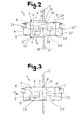
- FIG. 2 is still clearly seen that the locking elements 3, 3 'are each supported on the clutch housing 2 via a designed as a leaf spring spring tongue 7.
- a handle portion 6 By pressure on a handle portion 6, the locking elements 3 and 3 'can be compressed against each other (compressive force is indicated by F).
- FIG. 3 shows in which after pressurization, the locking elements are moved against the coupling housing.
- the acted upon by the leg portions or acted upon areas of the side wall 22 thereby form sliding surfaces for the leg portions 8, 9 in the sliding movement of the locking elements 3, 3 '.
- the engagement of the locking elements in the opening 4 of the front panel 5 is canceled.
- the coupling part 1 can now be pulled out of the opening in the direction of the arrow -e (opposite direction to the insertion direction).
- the clutch housing 2 has on two opposite side walls 22 via two elevations 23 and 23 '. Furthermore, an end portion 26 is arranged on both sides of the coupling housing 2 in the region of the plug openings for the plug parts, which forms a collar for guiding the latching elements 3 and 3 '.
- This coupling housing substantially corresponds to a known coupling housing, as it has been sold by the applicant for some time under the name "E-2000 TM simplex centerpiece". What is new, however, is the use of the locking elements 3 and 3 'described in more detail below, which, in combination with this coupling housing 2, which is already known per se, result in an advantageous coupling part, in particular with regard to handling. Of course, in principle, other types of coupling housings would be conceivable.
- the survey 23 is obviously the setting of the displacement direction F and limiting the displacement.
- the elevation 23 protrudes advantageous with respect to the sliding surface on which the locking element 3, 3 'slides in a sliding movement along, as far as before, that its flat outer surface is approximately flush with adjacent outer side of the locking element 3 extends.
- the depth of the elevation 23 (and 23 ') thus corresponds approximately to the thickness of the locking element.
- the regions of the side walls 24 which are acted upon by the latching elements 3, 3 ' are offset back relative to the end section 26 so far that the grip section 6 is in the compressed end position (FIG. Fig. 3 ) runs almost flush to the end portion 26
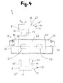
- FIG. 4 shows the coupling part 1 in disassembled state.
- FIG. 4 adjusted to the effect that of the locking elements 3 and 3 'only the observer facing the front sides, ie the leg portions 8, are shown.
- the end portion 26 defines a circumferential collar 25 which serves as a lateral guide for the movable in the direction of displacement locking elements 3 and 3 '.
- 31 and 31 'connector openings are designated for receiving connector parts.
- the elevation 23 can be seen, which is provided for engagement with the recess 13 of the upper locking element 3.
- the coupling housing 2 is constructed symmetrically with respect to a longitudinal plane. With 31 and 31 'plug openings for the connector parts are indicated.
- the elevations 23 (and 23 ') and the recess 13 have a rectangular shape in plan view.
- the front tip 19 of the pawl 10 is obviously rounded and allows easy insertion of the coupling part in the opening of a front panel.
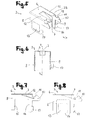
- FIGS. 5 to 8 is a single locking element 3 (or 3 ', both locking elements for the coupling part are the same design) shown.
- the locking element has a handle portion 6 and approximately perpendicular thereto subsequent Schenklabitese 8 and 9.
- One of the leg portions 8 is provided with a frame 14 and the recess 13 disposed therein.
- the other leg portion 9 has two guide portions (it can be seen here only the front guide portion 16), between which the frame of the second locking element would be feasible.
- the angle section 17 is arranged at the front end of the guide section 16 relative to the insertion direction.
- the locking element 3 is formed as a bent part made of metal.
- To the handle portion 6 close two approximately plane-parallel along the coupling housing 2 extending arm portions 12 at. Between the arm portions 12 a created by punching and bending operations spring tongue 7 is arranged as a leaf spring. The spring tongue 7 is angled at an acute angle relative to the arm portions 12 and extends in the insertion direction.
- FIG. 6 Illustratively shows the U-shape of the locking element 3. It can be seen that the leg portions 8 and 9 extend perpendicular to this connecting handle portion 6. With dashed lines, a rest position of the locking element is indicated. Evidently, the leg portion 8 and 9 are slightly inclined in the rest position relative to a plane extending at right angles inwards. In this way, a bias voltage can be generated, whereby the locking element can be securely held in the snapped position on the coupling housing.
Landscapes
- Physics & Mathematics (AREA)
- General Physics & Mathematics (AREA)
- Optics & Photonics (AREA)
- Mechanical Coupling Of Light Guides (AREA)
- Casings For Electric Apparatus (AREA)
Applications Claiming Priority (1)
| Application Number | Priority Date | Filing Date | Title |
|---|---|---|---|
| CH00534/07A CH698833B1 (de) | 2007-04-03 | 2007-04-03 | Kupplungsteil für eine Steckverbindung. |
Publications (2)
| Publication Number | Publication Date |
|---|---|
| EP1978386A2 true EP1978386A2 (fr) | 2008-10-08 |
| EP1978386A3 EP1978386A3 (fr) | 2009-03-11 |
Family
ID=39587871
Family Applications (1)
| Application Number | Title | Priority Date | Filing Date |
|---|---|---|---|
| EP08102431A Withdrawn EP1978386A3 (fr) | 2007-04-03 | 2008-03-10 | Pièce d'accouplement pour une connexion enfichable |
Country Status (2)
| Country | Link |
|---|---|
| EP (1) | EP1978386A3 (fr) |
| CH (1) | CH698833B1 (fr) |
Cited By (1)
| Publication number | Priority date | Publication date | Assignee | Title |
|---|---|---|---|---|
| CN109884750A (zh) * | 2019-01-14 | 2019-06-14 | 温州意华接插件股份有限公司 | 一种光纤连接器 |
Citations (2)
| Publication number | Priority date | Publication date | Assignee | Title |
|---|---|---|---|---|
| EP0974854A1 (fr) | 1998-07-21 | 2000-01-26 | Diamond SA | Module à fibre optique et dispositif pour le fixer sur une platine de support |
| EP1320770A2 (fr) | 2000-08-24 | 2003-06-25 | U.C. Laser Ltd. | Elements optiques de diffraction a volume interieur |
Family Cites Families (3)
| Publication number | Priority date | Publication date | Assignee | Title |
|---|---|---|---|---|
| US5418875A (en) * | 1992-09-04 | 1995-05-23 | Honda Tsushin Kogyo Co., Ltd. | Adapter for optical connector having float-type sleeve holder and panel fitting for mounting the same |
| EP1320777B1 (fr) * | 2000-09-26 | 2005-03-16 | KRONE GmbH | Dispositif de raccord pour connecteur de fibres optiques |
| US6909833B2 (en) * | 2002-03-15 | 2005-06-21 | Fiber Optic Network Solutions, Inc. | Optical fiber enclosure system using integrated optical connector and coupler assembly |
-
2007
- 2007-04-03 CH CH00534/07A patent/CH698833B1/de unknown
-
2008
- 2008-03-10 EP EP08102431A patent/EP1978386A3/fr not_active Withdrawn
Patent Citations (2)
| Publication number | Priority date | Publication date | Assignee | Title |
|---|---|---|---|---|
| EP0974854A1 (fr) | 1998-07-21 | 2000-01-26 | Diamond SA | Module à fibre optique et dispositif pour le fixer sur une platine de support |
| EP1320770A2 (fr) | 2000-08-24 | 2003-06-25 | U.C. Laser Ltd. | Elements optiques de diffraction a volume interieur |
Cited By (1)
| Publication number | Priority date | Publication date | Assignee | Title |
|---|---|---|---|---|
| CN109884750A (zh) * | 2019-01-14 | 2019-06-14 | 温州意华接插件股份有限公司 | 一种光纤连接器 |
Also Published As
| Publication number | Publication date |
|---|---|
| EP1978386A3 (fr) | 2009-03-11 |
| CH698833B1 (de) | 2009-11-13 |
Similar Documents
| Publication | Publication Date | Title |
|---|---|---|
| DE102013203289A9 (de) | Verbindungsmittel | |
| DE102015106854A1 (de) | Vorrichtung und Verfahren zum Festlegen eines Schubelementes | |
| DE102013111400A1 (de) | Befestigungsvorrichtung für zwei Befestigungszustände | |
| DE102016116178B4 (de) | Vorrichtung zur lösbaren Befestigung einer Frontblende an einem Schubkasten und Verfahren zur Montage oder Demontage einer Frontblende an einem Schubkasten | |
| DE102017113063A1 (de) | Tragschienenbefestigung | |
| DE102015106855A1 (de) | Vorrichtung und Verfahren zum Festlegen eines Schubelementes | |
| EP3682127B1 (fr) | Ensemble avec élément de fixation pour l'assemblage séparable de deux éléments de construction | |
| DE102015106856A1 (de) | Vorrichtung und Verfahren zum Festlegen eines Schubelementes | |
| DE102011010828A1 (de) | Klemmvorrichtung zur lösbaren Befestigung eines Gerätegehäuses an einer Profilschiene | |
| EP1978386A2 (fr) | Pièce d'accouplement pour une connexion enfichable | |
| DE102006005482B4 (de) | Vorrichtung zum verschiebbaren Halten einer Glasscheibe in einer Gleitschiene | |
| DE3246042C2 (de) | Verbindungsvorrichtung zum Herstellen einer lösbaren Steckverbindung | |
| AT525855B1 (de) | Kennzeichenhalter | |
| EP3228217B1 (fr) | Élément structurel | |
| CH683646A5 (de) | Steckverbindung für Lichtwellenleiter. | |
| DE102021108249A1 (de) | Koppelelement, Schließsystem und Möbel | |
| AT518987B1 (de) | Adapter für Rohrklemme | |
| DE102013110622A1 (de) | Vorrichtung zum Verbinden eines ersten Profilstabs mit einem zweiten Profilstab | |
| DE202011103129U1 (de) | Rastvorrichtung zur Befestigung von elektrischen Leitungen | |
| DE202018100943U1 (de) | Halterung zur Befestigung eines Objekts an einem Fenster- oder Türrahmen | |
| DE202022103073U1 (de) | Geraderichter zum Nutzentrennen von Nutzen in einem Nutzentrennwerkzeug, Nutzentrennwerkzeug und Stanzmaschine | |
| DE202012010758U1 (de) | Vorrichtung zur Befestigung einer Front an einem Seitenteil eines bewegbaren Möbelteils | |
| EP2474968B1 (fr) | Agencement de support enfichable et procédé de fabrication de profilés de support | |
| DE20101204U1 (de) | Nivelliereinrichtung | |
| DE102021117099A1 (de) | Montageeinrichtung für eine Verbindungseinrichtung, Verbindungseinrichtung sowie Verfahren zum Sichern einer Verbindungseinrichtung |
Legal Events
| Date | Code | Title | Description |
|---|---|---|---|
| PUAI | Public reference made under article 153(3) epc to a published international application that has entered the european phase |
Free format text: ORIGINAL CODE: 0009012 |
|
| AK | Designated contracting states |
Kind code of ref document: A2 Designated state(s): AT BE BG CH CY CZ DE DK EE ES FI FR GB GR HR HU IE IS IT LI LT LU LV MC MT NL NO PL PT RO SE SI SK TR |
|
| AX | Request for extension of the european patent |
Extension state: AL BA MK RS |
|
| PUAL | Search report despatched |
Free format text: ORIGINAL CODE: 0009013 |
|
| AK | Designated contracting states |
Kind code of ref document: A3 Designated state(s): AT BE BG CH CY CZ DE DK EE ES FI FR GB GR HR HU IE IS IT LI LT LU LV MC MT NL NO PL PT RO SE SI SK TR |
|
| AX | Request for extension of the european patent |
Extension state: AL BA MK RS |
|
| STAA | Information on the status of an ep patent application or granted ep patent |
Free format text: STATUS: THE APPLICATION IS DEEMED TO BE WITHDRAWN |
|
| 18D | Application deemed to be withdrawn |
Effective date: 20090912 |