EP1978393A1 - Appareil de projection d'image et objectif à focale variable - Google Patents
Appareil de projection d'image et objectif à focale variable Download PDFInfo
- Publication number
- EP1978393A1 EP1978393A1 EP08005652A EP08005652A EP1978393A1 EP 1978393 A1 EP1978393 A1 EP 1978393A1 EP 08005652 A EP08005652 A EP 08005652A EP 08005652 A EP08005652 A EP 08005652A EP 1978393 A1 EP1978393 A1 EP 1978393A1
- Authority
- EP
- European Patent Office
- Prior art keywords
- lens
- unit
- sub
- magnification
- zoom lens
- Prior art date
- Legal status (The legal status is an assumption and is not a legal conclusion. Google has not performed a legal analysis and makes no representation as to the accuracy of the status listed.)
- Granted
Links
Images


Classifications
-
- G—PHYSICS
- G02—OPTICS
- G02B—OPTICAL ELEMENTS, SYSTEMS OR APPARATUS
- G02B15/00—Optical objectives with means for varying the magnification
- G02B15/14—Optical objectives with means for varying the magnification by axial movement of one or more lenses or groups of lenses relative to the image plane for continuously varying the equivalent focal length of the objective
- G02B15/145—Optical objectives with means for varying the magnification by axial movement of one or more lenses or groups of lenses relative to the image plane for continuously varying the equivalent focal length of the objective having five groups only
- G02B15/1455—Optical objectives with means for varying the magnification by axial movement of one or more lenses or groups of lenses relative to the image plane for continuously varying the equivalent focal length of the objective having five groups only the first group being negative
- G02B15/145531—Optical objectives with means for varying the magnification by axial movement of one or more lenses or groups of lenses relative to the image plane for continuously varying the equivalent focal length of the objective having five groups only the first group being negative arranged -++++
-
- G—PHYSICS
- G02—OPTICS
- G02B—OPTICAL ELEMENTS, SYSTEMS OR APPARATUS
- G02B15/00—Optical objectives with means for varying the magnification
- G02B15/14—Optical objectives with means for varying the magnification by axial movement of one or more lenses or groups of lenses relative to the image plane for continuously varying the equivalent focal length of the objective
- G02B15/146—Optical objectives with means for varying the magnification by axial movement of one or more lenses or groups of lenses relative to the image plane for continuously varying the equivalent focal length of the objective having more than five groups
- G02B15/1465—Optical objectives with means for varying the magnification by axial movement of one or more lenses or groups of lenses relative to the image plane for continuously varying the equivalent focal length of the objective having more than five groups the first group being negative
Definitions
- the present invention relates to a zoom lens suitable for, for example, a projection lens used in an image projection apparatus (projector).
- Projectors require that a change in projection distance does not cause a significant change in quality of a projected image, that is, causes only small variation in performance of a projection lens.
- the projection lens often employs a so-called retrofocus type lens configuration in which a strong negative refractive power is disposed closer to a projection surface (screen) than an aperture stop.
- the retrofocus type lens has a feature that curvature of field due to the projection distance change is easily caused mainly by asymmetry of the lens, and therefore it is difficult to suppress the variation in performance of the projection lens due to the projection distance change. Moreover, an increase of a field angle of the retrofocus type lens for shortening the projection distance makes the curvature of field more obvious. Further, an image-forming element with high resolution decreases a permissive range of the curvature of field due to the projection distance change.
- a method called as floating has been conventionally used for reducing the curvature of field due to the projection distance change.
- plural lens units are simultaneously moved so as to mutually correct aberrations such as the curvature of field generated in the respective lens units.
- a lens configuration in which a first lens unit that is disposed closest to a magnification side and does not contribute to variation of magnification is divided into two lens sub-units to perform the floating, has a merit that no variation of focus position is caused by the variation of magnification.
- a so-called inner focus type zoom lens has been disclosed in Japanese Patent No. 3263835 and Japanese Patent Laid-Open No. 2001-124991 (corresponding to U.S. Patent No.6,686,988 ) in which a most-magnification side lens sub-unit is fixed and a reduction side lens sub-unit disposed next to the most-magnification side lens sub-unit on a reduction side is moved for focusing, which, however, is hard to be classified as the floating.
- the most-magnification side lens sub-unit has a negative refractive power and the reduction side lens sub-unit moved for focusing has a positive refractive power.
- a zoom lens has been disclosed in Japanese Patent Laid-Open No. 2006-234893 (corresponding to U.S. Patent No.7,190,528 ) in which a lens sub-unit having a negative refractive power and being disposed closer to the magnification side than a fixed lens sub-unit having a positive refractive power is moved for focusing.
- the zoom lens disclosed in Japanese Patent Laid-Open No. 2002-35771 has a negative refractive power as a whole, and therein the floating is performed by dividing the first lens unit that is unmoved for the variation of magnification into a first-A lens sub-unit and a first-B lens sub-unit respectively having a negative refractive power.
- the floating in a negative-negative type zoom lens is not suitable for miniaturization thereof because a lens movement amount is increased compared to a case where the focusing is performed by moving the entire first lens unit.
- the zoom lens disclosed in Japanese Patent No. 3263835 does not have a sufficient effect to correct variation of an image plane because a ratio of the refractive power of the first-B lens sub-unit to that of the entire first lens unit is large.
- the zoom lens disclosed therein is not suitable for a projection lens that needs to be telecentric on the reduction side because a most-reduction side lens unit thereof has a negative refractive power.
- the zoom lens disclosed in Japanese Patent Laid-Open No. 2001-124991 has an extremely small effective image circle, is insusceptible to the curvature of field, and includes the first-B lens sub-unit having an extremely small refractive power.
- the zoom lens is a zoom lens having an object different from that of the present invention.
- the zoom lens disclosed in Japanese Patent Laid-Open No. 2006-234893 improves the curvature of field to some extent compared to the case where the entire first lens unit is moved. However, it cannot provide a sufficient effect to remove the variation of the curvature of field.
- the present invention in its first aspect provides a zoom lens as specified in claims 1 and 3-8.
- the present invention in its second aspect provides a zoom lens as specified in claims 2 and 3-8.
- the present invention in its third aspect provides an image projection apparatus as specified in claim 9.
- FIG. 1 is a sectional view showing a zoom lens that is a first embodiment (Embodiment 1) of the present invention at a wide-angle end.
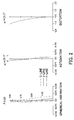
- FIG. 2 shows aberrations of the zoom lens of Embodiment 1 (numerical example) at the wide-angle end.
- FIG. 3 shows aberrations of the zoom lens of Embodiment 1 (numerical example) at a telephoto end.
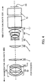
- FIG. 4 is a sectional view showing a zoom lens that is a second embodiment (Embodiment 2) of the present invention at a wide-angle end.
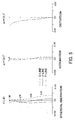
- FIG. 5 shows aberrations of the zoom lens of Embodiment 2 (numerical example) at the wide-angle end.
- FIG. 6 shows aberrations of the zoom lens of Embodiment 2 (numerical example) at a telephoto end.
- FIG. 7 is a sectional view showing a zoom lens that is a third embodiment (Embodiment 3) of the present invention at a wide-angle end.
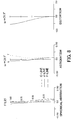
- FIG. 8 shows aberrations of the zoom lens of Embodiment 3 (numerical example) at the wide-angle end.
- FIG. 9 shows aberrations of the zoom lens of Embodiment 3 (numerical example) at a telephoto end.
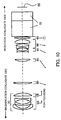
- FIG. 10 is a sectional view showing a zoom lens that is a fourth embodiment (Embodiment 4) of the present invention at a wide-angle end.
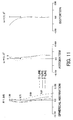
- FIG. 11 shows aberrations of the zoom lens of Embodiment 4 (numerical example) at the wide-angle end.
- FIG. 12 shows aberrations of the zoom lens of Embodiment 4 (numerical example) at a telephoto end.
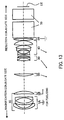
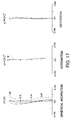
- FIG. 13 is a sectional view showing a zoom lens that is a fifth embodiment (Embodiment 5) of the present invention at a wide-angle end.
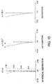
- FIG. 14 shows aberrations of the zoom lens of Embodiment 5 (numerical example) at the wide-angle end.
- FIG. 15 shows aberrations of the zoom lens of Embodiment 5 (numerical example) at a telephoto end.
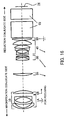
- FIG. 16 is a sectional view showing a zoom lens that is a sixth embodiment (Embodiment 6) of the present invention at a wide-angle end.
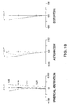
- FIG. 17 shows aberrations of the zoom lens of Embodiment 6 (numerical example) at the wide-angle end.
- FIG. 18 shows aberrations of the zoom lens of Embodiment 6 (numerical example) at a telephoto end.
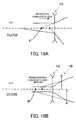
- FIGS. 19A and FIG. 19B are explanatory diagrams showing motions of lens units for focusing in each of the embodiments.
- FIG. 20 shows a configuration of a projector provided with the zoom lens of each of the embodiments.
- FIG. 20 shows the configuration of an image projection apparatus (projector) that is a first embodiment (Embodiment 1) of the present invention and provided with a zoom lens serving as a projection lens.
- reference numeral 303 denotes a liquid crystal driver.
- the liquid crystal driver 303 receives a video signal from an image supply apparatus 350 such as a personal computer, a DVD player, and a television tuner.
- the liquid crystal driver 303 converts the video signal into driving signals for a red (R) liquid crystal display element 3R, a green (G) liquid crystal display element 3G, and a blue (B) liquid crystal display element 3B, all of which are reflective liquid crystal display elements serving as image-forming elements.
- the red liquid crystal display element 3R, the green liquid crystal display element 3G, and the blue liquid crystal display element 3B are individually controlled.
- the projector and the image supply apparatus 350 constitute an image display system.
- Reference numeral 301 denotes an illumination optical system. Shown on the left in a box in FIG. 20 is a side view of the illumination optical system 301 shown on the right.
- the illumination optical system 301 converts white light emitted from a light source lamp 301a such as a high-pressure mercury lamp into linearly polarized light having a polarization direction perpendicular to the sheet of FIG. 20 and introduces the polarized light to a dichroic mirror 305.
- a light source lamp 301a such as a high-pressure mercury lamp
- the dichroic mirror 305 in this embodiment reflects a light component in magenta and transmits a light component in green.
- the magenta light component in the white light is deflected to be introduced to a blue cross color polarizer 311.
- the blue cross color polarizer 311 provides retardation of one-half wavelength for polarized light in blue. This produces a blue light component that is linearly polarized light having a polarization direction in parallel with the sheet of FIG. 20 and a red light component that is linearly polarized light having a polarization direction perpendicular to the sheet of FIG. 20 .
- the blue light component enters a first polarization beam splitter 310 as P-polarized light and then is transmitted through its polarization splitting film to be introduced to the liquid crystal display element 3B for blue.
- the red light component enters the first polarization beam splitter 310 as S-polarized light and then is reflected by the polarization splitting film to be introduced to the liquid crystal display element 3R for red.
- the green light component passes through a dummy glass 306 for correcting an optical path length of the green light component and then enters a second polarization beam splitter 307.
- the green light component having the polarization direction perpendicular to the sheet of FIG. 20 is S-polarized light for a polarization splitting film of the second polarization beam splitter 307, so that the green light component is reflected thereby to be introduced to the liquid crystal display element 3G for green.
- the illumination light components enter the red liquid crystal display element 3R, the green liquid crystal display element 3G, and the blue liquid crystal display element 3B.
- Each of the liquid crystal display elements provides retardation for the entering illumination light (polarized light) in accordance with the modulation state of pixels arranged on the liquid crystal display element.
- the light component polarized in the same direction as that of the illumination light is generally returned along the optical path of the illumination light toward the light source lamp 301a.
- image light formed of the light component polarized in the direction perpendicular to the polarization direction of the illumination light travels in the following manner.
- the red cross color polarizer 312 provides retardation of one-half wavelength for the red light component. This converts the red light component into linearly polarized light having the polarization direction perpendicular to the sheet of FIG. 20 .
- the red light component enters a third polarization beam splitter 308 as S-polarized light and then is reflected by its polarization splitting film toward a projection lens (projection optical system) 304.
- the blue light component enters the third polarization beam splitter 308 as S-polarized light and then is reflected by the polarization splitting film toward the projection lens 304.
- the blue light component enters the third polarization beam splitter 308 as P-polarized light and then is transmitted through the polarization splitting film to be introduced to the projection lens 304.
- the red, green, and blue light components are taken by an entrance pupil of the projection lens 304 to be transferred to a light diffusion screen (projection surface) 313.
- the light modulation surfaces of the respective liquid crystal display elements and the optical diffusion surface of the screen 313 are placed in an optically conjugate relationship by the projection lens 304. Therefore, an image based on the video signal is projected (displayed) on the screen 313.
- the red liquid crystal display element 3R, the green liquid crystal display element 3G, and the blue liquid crystal display element 3B are adjusted such that the light components from the associated pixels overlap each other on the screen 313 with predetermined accuracy.
- FIG. 1 shows an optical section of the zoom lens at a wide-angle end.
- the zoom lens of this embodiment is constituted by six lens units 10, 20, 30, 40, 50, and 60 including thirteen lens elements.
- Reference numeral 70 denotes the above-described polarization beam splitter, and reference character IE denotes the above-described liquid crystal display element.
- the six lens units 10 to 60 have, in order from a magnification conjugate side (also merely referred to as a magnification side) to a reduction conjugate side (also merely referred to as a reduction side), negative, positive, positive, positive, negative, and positive refractive powers.
- the refractive power can also be said as the optical power that is represented by an inverse of a focal length of the lens unit.
- each lens unit is constituted by one or plurality of lens elements and may include other optical element than the lens element, such as a diffractive optical element attached to a lens surface.
- the second and seventh lens elements counted from the magnification side respectively have aspheric surfaces on their both sides.
- zooming For variation of magnification (hereinafter referred to as zooming), the second, third, fourth, and fifth lens units 20 to 50 are moved in an optical axis direction, and the first and sixth lens units 10 and 60 are fixed (unmoved).
- the first and sixth lens units 10 and 60 do not contribute to the variation of magnification, and the second, third, fourth, and fifth lens units 20 to 50 are magnification-varying lens units.
- the first lens unit 10 includes a first-A lens sub-unit (shown by reference character 1A in the figure) and a first-B lens sub-unit (shown by reference character 1B in the figure).
- the first-A lens sub-unit is disposed closer to the magnification conjugate side than the first-B lens sub-unit and has a negative refractive power
- the first-B lens sub-unit is disposed closer to the reduction conjugate side than the first-A lens sub-unit and has a positive refractive power.
- the first-A and first-B lens sub-units are moved toward the reduction conjugate side as a distance therebetween is increased.
- FIG. 19A shows movement of the reduction side conjugate point (reduction conjugate side principal point) F' due to the motion of the entire first lens unit associated with change of a magnification conjugate side distance.
- magnification conjugate side distance is changed from the infinite side (far side) to the close side (near side)
- the reduction side conjugate point F' is moved therewith toward the reduction conjugate side.
- the change of the distance between the first-A lens sub-unit and the first-B lens sub-unit varies a synthesized focal length of the entire first lens unit.
- the change amount of the distance between the first-A and first-B lens sub-units is sufficiently smaller than the change amount of the magnification conjugate side distance, so that it hardly influences the movement direction and movement amount of the reduction side conjugate point F'.
- FIG. 19B shows movement of the reduction side conjugate point H' due to the change of the distance between the first-A lens sub-unit and the first-B lens sub-unit.
- the motion of the first-B lens sub-unit toward the reduction conjugate side produces curvature of field in an under direction.
- the first-B lens sub-unit is moved away from the first-A lens sub-unit.
- the reduction side conjugate point H' of the entire first lens unit is moved toward the magnification conjugate side.
- the movement amount of the reduction side conjugate point H' shown in FIG. 19B is larger than that of the reduction side conjugate point F' shown in FIG.19A . Therefore, in focusing from the infinite side to the close side, the first-B lens sub-unit is inevitably moved (retracted) toward the reduction conjugate side.
- the motion of the first-A lens sub-unit can be arbitrarily adjusted by changing the refractive power of the first-B lens sub-unit.
- the refractive power of the first-B lens sub-unit basically has no limitation.
- f 1A represents a focal length of the first-A lens sub-unit
- f 1B a focal length of the first-B lens sub-unit
- f 1 a focal length of the entire first lens unit.
- f w represents a focal length of the entire zoom lens at the wide-angle end, and bf a back focus in air from a most-reduction side lens surface in the zoom lens to a reduction-side conjugate plane of the zoom lens.
- the refractive power of the first-B lens sub-unit is set such that the movement amount of the reduction side conjugate point shown in FIG. 19A is equal to that shown in FIG. 19B , the first-A lens sub-unit can be fixed (unmoved) for focusing.
- the refractive power of the first-B lens sub-unit in other words, a ratio of the refractive power of the first-B lens sub-unit to that of the entire first lens unit satisfy the condition (1).
- the ratio is larger than the lower limit of the condition (1), focusing can be performed while preventing variation of the curvature of field from being insufficiently corrected due to lack of the curvature of field in the under direction. If the ratio is smaller than the upper limit of the condition (1), focusing can be performed while preventing the movement amount of the first-B lens sub-unit from being increased and while preventing the variation of the curvature of field from being magnified due to generation of the curvature of field in the over direction.
- the condition (2) represents desirable shapes of the lens surfaces of the first-B lens sub-unit.
- the value of SF larger than the lower limit of the condition (2) makes it possible to sufficiently ensure the amount of the curvature of field generated in the under direction for correction of the curvature of field.
- the value of SF smaller than the upper limit of the condition (2) makes it possible to prevent the correction from being excessive.
- the condition (3) represents a ratio of the refractive power of the first-A lens sub-unit to that of the first-B lens sub-unit. Satisfying the condition (3) can realize focusing by the negative-positive floating while achieving a long back focus and well-balanced aberration correction.
- the condition (4) relates to the back focus of the zoom lens. If the absolute value of f w /bf satisfies the condition (4), an adequate back focus for projectors can be obtained.
- a most-reduction side lens unit in the zoom lens (sixth lens unit 60 in this embodiment) have a positive refractive power and be fixed (unmoved) for focusing.
- the projection lens for projectors needs to be telecentric on the reduction conjugate side as well as image-pickup lenses for image-pickup apparatuses using an image-pickup element such as a CCD sensor and a CMOS sensor.
- the most-reduction side lens unit having a positive refractive power is advantageous to such a projection lens.
- a most-reduction side lens surface of the first-B lens sub-unit be a convex surface toward the reduction conjugate side because the convex lens surface generates the curvature of field in the under direction.
- the most-reduction side lens surface and the most-magnification side lens surface of the first-B lens sub-unit are convex surfaces toward the reduction conjugate side, a correction effect for the curvature of field can be increased because each lens surfaces can correct the curvature of field.
- the first-B lens sub-unit constituted by one meniscus lens element whose both side surfaces are convex toward the reduction conjugate side enables provision of a high effect for correcting the curvature of field and simplification of the lens configuration.
- conditions (1) to (6) are not indispensable ones for embodiments of the present invention but ones to obtain preferable effects. In other words, it is preferable to satisfy at least one of the conditions (1) to (6), and more preferably, all of them.
- Table 1 shows a numerical example of this embodiment.
- f represents the focal length (mm) of the zoom lens, ⁇ a half field angle, and F an F-number.
- Surface numbers in Table 1 represent numbers assigned to the lens surfaces in order from the screen side (magnification conjugate side).
- r represents a curvature radius of each lens surface, and d a distance (physical distance) (mm) between the lens surfaces adjacent to each other.
- n d and ⁇ d respectively represent a refractive index and an Abbe number for d-line of glass material forming the lens elements.
- the distance between the lens surfaces marked with z in Table 1 is changed with zooming or focusing, and the values thereof at W (wide-angle end), M (middle position), and T (telephoto end) are shown in Table 1.
- the lens surface whose number is marked with * on its right side has an aspheric shape defined by the following function, and aspheric coefficients are shown in Table 1.
- y represents a coordinate in a lens diameter direction
- x a coordinate in the optical axis direction.
- "e ⁇ X" represents " ⁇ 10 ⁇ x ".
- FIGS. 2 and 3 respectively show aberrations (spherical aberration, astigmatism, and distortion) of the zoom lens in this numerical example at the wide-angle end and at the telephoto end, the projection distance being 2.1 m.
- FIG. 4 shows an optical section of a zoom lens (projection lens) that is a second embodiment (Embodiment 2) of the present invention at a wide-angle end.
- the lens configuration of this embodiment is basically identical to that in Embodiment 1.
- the refractive power of the first-B lens sub-unit is significantly different from that in Embodiment 1, which provides the movement amount of the image side principal point and the movement of the image point that are well-balanced to each other and therefore fixes (does not move) the first-A lens sub-unit for focusing.
- the first-B lens sub-unit has an extremely small decentration sensitivity.
- productivity of the zoom lens can be improved compared to a case where the first-A and first-B lens sub-units are both moved for focusing and a case where the entire first lens unit is moved for focusing.
- the refractive power of the first-B lens sub-unit in other words, the ratio of the refractive power of the first-B lens sub-unit to that of the entire first lens unit satisfy the condition (1). Further, it is preferable to satisfy at least one of the conditions (2) to (4) for the reasons described in Embodiment 1.
- Table 2 shows a numerical example of this embodiment.
- FIGS. 5 and 6 respectively show aberrations of the zoom lens in this numerical example at the wide-angle end and at the telephoto end, the projection distance being 2.1 m.
- FIG. 7 shows an optical section of a zoom lens (projection lens) that is a third embodiment (Embodiment 3) of the present invention at a wide-angle end.
- the lens configuration and a focusing method of this embodiment are basically identical to those in Embodiment 1.
- the zoom lens uses a lens unit having a positive refractive power for the first lens unit 10 and a so-called replica aspheric surface formed of a resin material for the magnification conjugate side surface of the second lens unit 20.
- a lens element having a positive refractive power is provided in the first-A lens sub-unit, which reduces the ratio of the refractive power of the first-B lens sub-unit to that of the entire first lens unit compared to the ratio in Embodiment 2.
- Table 3 shows a numerical example of this embodiment.
- FIGS. 8 and 9 respectively show aberrations of the zoom lens in this numerical example at the wide-angle end and at the telephoto end, the projection distance being 2.1 m.
- FIG. 10 shows an optical section of a zoom lens (projection lens) that is a fourth embodiment (Embodiment 4) of the present invention at a wide-angle end.
- the zoom lens of this embodiment is constituted by six lens units 10, 20, 30, 40, 50, and 60 including twelve lens elements.
- the six lens units 10 to 60 have, in order from the magnification conjugate side, negative, positive, positive, negative, positive, and positive refractive powers.
- a second lens element in the twelve lens elements, which is counted from the magnification conjugate side, has aspheric surfaces on its both sides.
- the second, third, fourth, and fifth lens units 20 to 50 are moved, and the first and sixth lens units 10 and 60 are fixed (unmoved). In other words, the first and sixth lens units 10 and 60 do not contribute to zooming, and the second, third, fourth, and fifth lens units 20 to 50 are magnification-varying lens units.
- a first-A lens sub-unit and a first-B lens sub-unit are both moved toward the reduction conjugate side as a distance therebetween is increased.
- FIGS. 11 and 12 respectively show aberrations of the zoom lens in this numerical example at the wide-angle end and at the telephoto end, the projection distance being 2.1 m.
- FIG. 13 shows an optical section of a zoom lens (projection lens) that is a fifth embodiment (Embodiment 5) of the present invention at a wide-angle end.
- the zoom lens of this embodiment is constituted by five lens units 10, 20, 30, 40, and 50 including fifteen lens elements.
- the five lens units 10 to 50 have, in order from the magnification conjugate side, negative, positive, positive, positive, and positive refractive powers.
- a second lens element in the fifteen lens elements, which is counted from the magnification conjugate side, has aspheric surfaces on its both sides.
- the second, third, and fourth lens units 20 to 40 are moved, and the first and fifth lens units 10 and 50 are fixed (unmoved). In other words, the first and fifth lens units 10 and 50 do not contribute to zooming, and the second, third, and fourth lens units 20 to 40 are magnification-varying lens units.
- a first-A lens sub-unit is fixed in focusing. In other words, only a first-B lens sub-unit is moved for focusing.
- Table 5 shows a numerical example of this embodiment.
- FIGS. 14 and 15 respectively show aberrations of the zoom lens in this numerical example at the wide-angle end and at the telephoto end, the projection distance being 2.1 m.
- FIG. 16 shows an optical section of a zoom lens (projection lens) that is a sixth embodiment (Embodiment 6) of the present invention at a wide-angle end.
- the zoom lens of this embodiment is constituted by five lens units 10, 20, 30, 40, and 50 including fifteen lens elements.
- the five lens units 10 to 50 have, in order from the magnification conjugate side, negative, positive, positive, negative, and positive refractive powers.
- a second lens element in the fifteen lens elements, which is counted from the magnification conjugate side, has aspheric surfaces on its both sides.
- the second, third, and fourth lens units 20 to 40 are moved, and the first and fifth lens units 10 and 50 are fixed (unmoved). In other words, the first and fifth lens units 10 and 50 do not contribute to zooming, and the second, third, and fourth lens units 20 to 40 are magnification-varying lens units.
- a first-A lens sub-unit is fixed in focusing. In other words, only a first-B lens sub-unit is moved for focusing.
- FIGS. 17 and 18 respectively show aberrations of the zoom lens in this numerical example at the wide-angle end and at the telephoto end, the projection distance being 2.1 m.
- the zoom lens of each of the embodiments can correct well the variation of curvature of field due to the projection distance change in a wide projection distance range from a close distance to an infinite distance, thereby enabling the achievement of the zoom lens having a good optical performance.
- the zoom lens of an alternative embodiment of the present invention can be used as an image-taking lens for an image-pickup apparatus such as a video camera and a digital still camera.
Landscapes
- Physics & Mathematics (AREA)
- General Physics & Mathematics (AREA)
- Optics & Photonics (AREA)
- Lenses (AREA)
- Projection Apparatus (AREA)
Applications Claiming Priority (1)
| Application Number | Priority Date | Filing Date | Title |
|---|---|---|---|
| JP2007100111A JP5063165B2 (ja) | 2007-04-06 | 2007-04-06 | ズームレンズ及び画像投射装置 |
Publications (2)
| Publication Number | Publication Date |
|---|---|
| EP1978393A1 true EP1978393A1 (fr) | 2008-10-08 |
| EP1978393B1 EP1978393B1 (fr) | 2015-09-02 |
Family
ID=39643910
Family Applications (1)
| Application Number | Title | Priority Date | Filing Date |
|---|---|---|---|
| EP08005652.6A Active EP1978393B1 (fr) | 2007-04-06 | 2008-03-26 | Appareil de projection d'image et objectif à focale variable |
Country Status (4)
| Country | Link |
|---|---|
| US (1) | US7576921B2 (fr) |
| EP (1) | EP1978393B1 (fr) |
| JP (1) | JP5063165B2 (fr) |
| CN (1) | CN101281291B (fr) |
Cited By (2)
| Publication number | Priority date | Publication date | Assignee | Title |
|---|---|---|---|---|
| EP2680057A1 (fr) * | 2012-06-28 | 2014-01-01 | Leica Camera AG | Objectif grand angle de type rétrofocus modifié |
| US20210341715A1 (en) * | 2019-01-25 | 2021-11-04 | Panasonic Intellectual Property Management Co., Ltd. | Optical system, image projection apparatus, and imaging apparatus |
Families Citing this family (25)
| Publication number | Priority date | Publication date | Assignee | Title |
|---|---|---|---|---|
| JP2010160478A (ja) * | 2008-12-08 | 2010-07-22 | Fujinon Corp | 投写用ズームレンズおよび投写型表示装置 |
| JP5608986B2 (ja) * | 2009-02-26 | 2014-10-22 | 株式会社ニコン | 変倍光学系、光学機器 |
| JP5608987B2 (ja) * | 2009-02-26 | 2014-10-22 | 株式会社ニコン | 変倍光学系、光学機器 |
| US8503097B2 (en) | 2009-05-27 | 2013-08-06 | Nikon Corporation | Lens system, optical apparatus and manufacturing method |
| JP5369898B2 (ja) * | 2009-05-27 | 2013-12-18 | 株式会社ニコン | ズームレンズ、光学機器 |
| JP2011013657A (ja) * | 2009-06-05 | 2011-01-20 | Fujifilm Corp | 投写用ズームレンズおよび投写型表示装置 |
| JP5363202B2 (ja) * | 2009-06-08 | 2013-12-11 | 富士フイルム株式会社 | 投写用ズームレンズおよび投写型表示装置 |
| JP2010282159A (ja) * | 2009-06-08 | 2010-12-16 | Fujifilm Corp | 投写用ズームレンズおよび投写型表示装置 |
| JP5302123B2 (ja) * | 2009-07-14 | 2013-10-02 | 富士フイルム株式会社 | 投影用ズームレンズおよび投写型表示装置 |
| JP5603292B2 (ja) * | 2010-06-15 | 2014-10-08 | 富士フイルム株式会社 | 投影用ズームレンズおよび投写型表示装置 |
| WO2012077278A1 (fr) | 2010-12-07 | 2012-06-14 | 株式会社ニコン | Objectif zoom, dispositif d'imagerie, et procédé de production d'objectif zoom |
| JP5333955B2 (ja) * | 2011-03-01 | 2013-11-06 | 株式会社ニコン | ズームレンズ、撮像装置及びズームレンズの製造方法 |
| JP5724639B2 (ja) * | 2011-05-30 | 2015-05-27 | リコーイメージング株式会社 | ズームレンズ系及びこれを用いた光学機器 |
| WO2013001759A1 (fr) * | 2011-06-27 | 2013-01-03 | 富士フイルム株式会社 | Système optique à grossissement variable pour projection, et dispositif d'affichage par projection |
| WO2013001804A1 (fr) * | 2011-06-29 | 2013-01-03 | 富士フイルム株式会社 | Système optique à grossissement variable pour projection, et dispositif d'affichage par projection |
| JP5637110B2 (ja) | 2011-09-21 | 2014-12-10 | コニカミノルタ株式会社 | インナーフォーカスズームレンズ |
| CN203930190U (zh) | 2011-10-20 | 2014-11-05 | 富士胶片株式会社 | 投影用变焦镜头和投影型显示设备 |
| JP5988297B2 (ja) * | 2012-08-13 | 2016-09-07 | コニカミノルタ株式会社 | 変倍投射光学系および画像投影装置 |
| CN204925499U (zh) | 2012-11-19 | 2015-12-30 | 富士胶片株式会社 | 投影用变焦透镜以及投影型显示装置 |
| JP2014235217A (ja) | 2013-05-31 | 2014-12-15 | 富士フイルム株式会社 | 投写用レンズおよび投写型表示装置 |
| JP6383214B2 (ja) * | 2014-08-05 | 2018-08-29 | オリンパス株式会社 | 結像光学系及びそれを備えた光学装置 |
| JP6415258B2 (ja) * | 2014-11-14 | 2018-10-31 | キヤノン株式会社 | 結像光学系および画像投射装置 |
| JP6536039B2 (ja) * | 2015-01-22 | 2019-07-03 | セイコーエプソン株式会社 | 投射光学系及び投射型画像表示装置 |
| US9720215B2 (en) * | 2015-11-27 | 2017-08-01 | Coretronic Corporation | Zoom lens |
| JP7694363B2 (ja) * | 2021-12-01 | 2025-06-18 | セイコーエプソン株式会社 | 投写光学系、およびプロジェクター |
Citations (6)
| Publication number | Priority date | Publication date | Assignee | Title |
|---|---|---|---|---|
| US4124274A (en) | 1976-01-28 | 1978-11-07 | Canon Kabushiki Kaisha | Zoom lens having closeup focusing control |
| US5631775A (en) | 1993-11-16 | 1997-05-20 | Olympus Optical Co., Ltd. | Zoom lens system |
| JPH10186235A (ja) | 1996-10-24 | 1998-07-14 | Koshina:Kk | 投映用ズームレンズ |
| US20020181120A1 (en) * | 2001-03-27 | 2002-12-05 | Akiko Nagahara | Wide-angle zoom lens and projection-type display unit using it |
| US20060187556A1 (en) * | 2005-02-22 | 2006-08-24 | Kazuhiro Inoko | Zoom lens and image projection apparatus having the same |
| US20070030576A1 (en) | 2005-08-05 | 2007-02-08 | Takeo Arai | Telecentric zoom lens |
Family Cites Families (16)
| Publication number | Priority date | Publication date | Assignee | Title |
|---|---|---|---|---|
| JPS61121021A (ja) * | 1984-11-16 | 1986-06-09 | Canon Inc | ソフトフオ−カス機能を有するズ−ムレンズ |
| JP2862272B2 (ja) * | 1989-05-11 | 1999-03-03 | キヤノン株式会社 | 広角ズームレンズ |
| JPH04406A (ja) * | 1990-04-18 | 1992-01-06 | Konica Corp | 近接撮影可能なズームレンズ |
| JP3360387B2 (ja) * | 1993-11-15 | 2002-12-24 | 株式会社ニコン | 投影光学系及び投影露光装置 |
| US6028716A (en) * | 1993-11-29 | 2000-02-22 | Canon Kabushiki Kaisha | Zoom lens |
| JP3263835B2 (ja) * | 1994-03-24 | 2002-03-11 | 株式会社シグマ | 超広角ズームレンズ |
| JP2001124991A (ja) | 1999-10-28 | 2001-05-11 | Canon Inc | 立体撮影用光学系及びそれを用いた立体撮像装置 |
| JP4097957B2 (ja) | 2001-03-27 | 2008-06-11 | フジノン株式会社 | 広角ズームレンズおよびこれを用いた投写型表示装置 |
| JP2004093593A (ja) * | 2002-08-29 | 2004-03-25 | Konica Minolta Holdings Inc | ズームレンズ |
| JP4322567B2 (ja) * | 2003-06-20 | 2009-09-02 | パナソニック株式会社 | ズームレンズ、並びにそれを用いた映像拡大投写システム及びビデオプロジェクタ、並びにそのビデオプロジェクタを用いたリアプロジェクタ及びマルチビジョンシステム |
| US6989939B2 (en) * | 2003-08-11 | 2006-01-24 | Canon Kabushiki Kaisha | Variable-power optical system, projection optical system, and image projection apparatus using the systems |
| JP2005062771A (ja) * | 2003-08-20 | 2005-03-10 | Olympus Corp | ズームレンズ及びそれを用いたカメラ |
| JP2005106878A (ja) * | 2003-09-29 | 2005-04-21 | Sigma Corp | 超広角レンズ系 |
| EP1577695B1 (fr) * | 2004-01-30 | 2008-02-27 | Casio Computer Co., Ltd. | Sytème d'objectif à focale variable |
| JP4624744B2 (ja) * | 2004-08-31 | 2011-02-02 | オリンパス株式会社 | 広角ズームレンズ |
| JP4687194B2 (ja) * | 2005-03-30 | 2011-05-25 | 株式会社ニコン | ズームレンズ |
-
2007
- 2007-04-06 JP JP2007100111A patent/JP5063165B2/ja active Active
-
2008
- 2008-03-26 EP EP08005652.6A patent/EP1978393B1/fr active Active
- 2008-03-26 US US12/055,637 patent/US7576921B2/en active Active
- 2008-04-02 CN CN200810090064XA patent/CN101281291B/zh active Active
Patent Citations (6)
| Publication number | Priority date | Publication date | Assignee | Title |
|---|---|---|---|---|
| US4124274A (en) | 1976-01-28 | 1978-11-07 | Canon Kabushiki Kaisha | Zoom lens having closeup focusing control |
| US5631775A (en) | 1993-11-16 | 1997-05-20 | Olympus Optical Co., Ltd. | Zoom lens system |
| JPH10186235A (ja) | 1996-10-24 | 1998-07-14 | Koshina:Kk | 投映用ズームレンズ |
| US20020181120A1 (en) * | 2001-03-27 | 2002-12-05 | Akiko Nagahara | Wide-angle zoom lens and projection-type display unit using it |
| US20060187556A1 (en) * | 2005-02-22 | 2006-08-24 | Kazuhiro Inoko | Zoom lens and image projection apparatus having the same |
| US20070030576A1 (en) | 2005-08-05 | 2007-02-08 | Takeo Arai | Telecentric zoom lens |
Cited By (5)
| Publication number | Priority date | Publication date | Assignee | Title |
|---|---|---|---|---|
| EP2680057A1 (fr) * | 2012-06-28 | 2014-01-01 | Leica Camera AG | Objectif grand angle de type rétrofocus modifié |
| US8665537B2 (en) | 2012-06-28 | 2014-03-04 | Leica Camera Ag | Modified retrofocus-type wide-angle lens |
| US20210341715A1 (en) * | 2019-01-25 | 2021-11-04 | Panasonic Intellectual Property Management Co., Ltd. | Optical system, image projection apparatus, and imaging apparatus |
| EP3916461A4 (fr) * | 2019-01-25 | 2022-03-09 | Panasonic Intellectual Property Management Co., Ltd. | Système optique, dispositif de projection d'image et dispositif d'imagerie |
| US12253659B2 (en) | 2019-01-25 | 2025-03-18 | Panasonic Intellectual Property Management Co., Ltd. | Optical system, image projection apparatus, and imaging apparatus |
Also Published As
| Publication number | Publication date |
|---|---|
| EP1978393B1 (fr) | 2015-09-02 |
| CN101281291B (zh) | 2010-06-16 |
| US7576921B2 (en) | 2009-08-18 |
| US20080247049A1 (en) | 2008-10-09 |
| CN101281291A (zh) | 2008-10-08 |
| JP2008257005A (ja) | 2008-10-23 |
| JP5063165B2 (ja) | 2012-10-31 |
Similar Documents
| Publication | Publication Date | Title |
|---|---|---|
| EP1978393A1 (fr) | Appareil de projection d'image et objectif à focale variable | |
| US7545578B2 (en) | Image projection optical system and image projection apparatus | |
| US7817345B2 (en) | Zoom lens and image projection apparatus including the same | |
| US7079324B2 (en) | Zoom lens and image projection apparatus including the same | |
| JP6587590B2 (ja) | ズームレンズ、投写型表示装置、および、撮像装置 | |
| JP5053694B2 (ja) | 投射用ズームレンズ、光学ユニット及び画像投射装置 | |
| US20150234167A1 (en) | Zoom optical system and image projection apparatus having the same | |
| JP6587591B2 (ja) | ズームレンズ、投写型表示装置、および、撮像装置 | |
| US11280986B2 (en) | Zoom lens, projection display device, and imaging apparatus for forming an intermediate image | |
| US6985302B2 (en) | Projection zoom lens and optical projector provided with the same | |
| JP2017211478A (ja) | 結像光学系、投写型表示装置、および、撮像装置 | |
| JP4599071B2 (ja) | ズームレンズ及びそれを有する画像投射装置 | |
| JP5253604B2 (ja) | ズームレンズ及び画像投射装置 | |
| US10416422B2 (en) | Zoom lens, projection display device, and imaging apparatus for forming an intermediate image | |
| JP4551676B2 (ja) | ズームレンズ、画像表示装置、撮像装置 | |
| JP5031391B2 (ja) | テレセントリックな広角ズームレンズ | |
| JP2018036381A (ja) | ズームレンズ、撮像装置、および投写型表示装置 | |
| US10324278B2 (en) | Zoom lens, projection display device, and imaging apparatus | |
| JP2001350094A (ja) | 光学系、投射光学系及びそれを有する画像投影装置、撮像装置 | |
| JP6556106B2 (ja) | ズームレンズ、投写型表示装置、および、撮像装置 | |
| JP6639358B2 (ja) | ズームレンズ、投写型表示装置、および、撮像装置 |
Legal Events
| Date | Code | Title | Description |
|---|---|---|---|
| PUAI | Public reference made under article 153(3) epc to a published international application that has entered the european phase |
Free format text: ORIGINAL CODE: 0009012 |
|
| AK | Designated contracting states |
Kind code of ref document: A1 Designated state(s): AT BE BG CH CY CZ DE DK EE ES FI FR GB GR HR HU IE IS IT LI LT LU LV MC MT NL NO PL PT RO SE SI SK TR |
|
| AX | Request for extension of the european patent |
Extension state: AL BA MK RS |
|
| 17P | Request for examination filed |
Effective date: 20090408 |
|
| AKX | Designation fees paid |
Designated state(s): DE FR GB NL |
|
| 17Q | First examination report despatched |
Effective date: 20100111 |
|
| GRAP | Despatch of communication of intention to grant a patent |
Free format text: ORIGINAL CODE: EPIDOSNIGR1 |
|
| INTG | Intention to grant announced |
Effective date: 20150324 |
|
| GRAS | Grant fee paid |
Free format text: ORIGINAL CODE: EPIDOSNIGR3 |
|
| GRAA | (expected) grant |
Free format text: ORIGINAL CODE: 0009210 |
|
| AK | Designated contracting states |
Kind code of ref document: B1 Designated state(s): DE FR GB NL |
|
| REG | Reference to a national code |
Ref country code: GB Ref legal event code: FG4D |
|
| RIN1 | Information on inventor provided before grant (corrected) |
Inventor name: INOKO, KAZUHIRO |
|
| REG | Reference to a national code |
Ref country code: DE Ref legal event code: R096 Ref document number: 602008039881 Country of ref document: DE |
|
| REG | Reference to a national code |
Ref country code: NL Ref legal event code: MP Effective date: 20150902 |
|
| PG25 | Lapsed in a contracting state [announced via postgrant information from national office to epo] |
Ref country code: NL Free format text: LAPSE BECAUSE OF FAILURE TO SUBMIT A TRANSLATION OF THE DESCRIPTION OR TO PAY THE FEE WITHIN THE PRESCRIBED TIME-LIMIT Effective date: 20150902 |
|
| REG | Reference to a national code |
Ref country code: DE Ref legal event code: R097 Ref document number: 602008039881 Country of ref document: DE |
|
| PLBE | No opposition filed within time limit |
Free format text: ORIGINAL CODE: 0009261 |
|
| STAA | Information on the status of an ep patent application or granted ep patent |
Free format text: STATUS: NO OPPOSITION FILED WITHIN TIME LIMIT |
|
| 26N | No opposition filed |
Effective date: 20160603 |
|
| REG | Reference to a national code |
Ref country code: FR Ref legal event code: ST Effective date: 20161130 |
|
| PG25 | Lapsed in a contracting state [announced via postgrant information from national office to epo] |
Ref country code: FR Free format text: LAPSE BECAUSE OF NON-PAYMENT OF DUE FEES Effective date: 20160331 |
|
| PGFP | Annual fee paid to national office [announced via postgrant information from national office to epo] |
Ref country code: GB Payment date: 20260219 Year of fee payment: 19 |
|
| PGFP | Annual fee paid to national office [announced via postgrant information from national office to epo] |
Ref country code: DE Payment date: 20260219 Year of fee payment: 19 |