EP1978528A1 - Kraftstoffanordnung und einsetzbare interelementabstandsvorrichtung - Google Patents
Kraftstoffanordnung und einsetzbare interelementabstandsvorrichtung Download PDFInfo
- Publication number
- EP1978528A1 EP1978528A1 EP07793996A EP07793996A EP1978528A1 EP 1978528 A1 EP1978528 A1 EP 1978528A1 EP 07793996 A EP07793996 A EP 07793996A EP 07793996 A EP07793996 A EP 07793996A EP 1978528 A1 EP1978528 A1 EP 1978528A1
- Authority
- EP
- European Patent Office
- Prior art keywords
- spacing
- fuel
- insertable
- facets
- cell
- Prior art date
- Legal status (The legal status is an assumption and is not a legal conclusion. Google has not performed a legal analysis and makes no representation as to the accuracy of the status listed.)
- Granted
Links
Images


Classifications
-
- G—PHYSICS
- G21—NUCLEAR PHYSICS; NUCLEAR ENGINEERING
- G21C—NUCLEAR REACTORS
- G21C3/00—Reactor fuel elements and their assemblies; Selection of substances for use as reactor fuel elements
- G21C3/30—Assemblies of a number of fuel elements in the form of a rigid unit
- G21C3/32—Bundles of parallel pin-, rod-, or tube-shaped fuel elements
- G21C3/322—Means to influence the coolant flow through or around the bundles
-
- G—PHYSICS
- G21—NUCLEAR PHYSICS; NUCLEAR ENGINEERING
- G21C—NUCLEAR REACTORS
- G21C3/00—Reactor fuel elements and their assemblies; Selection of substances for use as reactor fuel elements
- G21C3/30—Assemblies of a number of fuel elements in the form of a rigid unit
- G21C3/32—Bundles of parallel pin-, rod-, or tube-shaped fuel elements
- G21C3/34—Spacer grids
- G21C3/344—Spacer grids formed of assembled tubular elements
-
- G—PHYSICS
- G21—NUCLEAR PHYSICS; NUCLEAR ENGINEERING
- G21C—NUCLEAR REACTORS
- G21C3/00—Reactor fuel elements and their assemblies; Selection of substances for use as reactor fuel elements
- G21C3/30—Assemblies of a number of fuel elements in the form of a rigid unit
- G21C3/32—Bundles of parallel pin-, rod-, or tube-shaped fuel elements
- G21C3/34—Spacer grids
- G21C3/352—Spacer grids formed of assembled intersecting strips
-
- Y—GENERAL TAGGING OF NEW TECHNOLOGICAL DEVELOPMENTS; GENERAL TAGGING OF CROSS-SECTIONAL TECHNOLOGIES SPANNING OVER SEVERAL SECTIONS OF THE IPC; TECHNICAL SUBJECTS COVERED BY FORMER USPC CROSS-REFERENCE ART COLLECTIONS [XRACs] AND DIGESTS
- Y02—TECHNOLOGIES OR APPLICATIONS FOR MITIGATION OR ADAPTATION AGAINST CLIMATE CHANGE
- Y02E—REDUCTION OF GREENHOUSE GAS [GHG] EMISSIONS, RELATED TO ENERGY GENERATION, TRANSMISSION OR DISTRIBUTION
- Y02E30/00—Energy generation of nuclear origin
- Y02E30/30—Nuclear fission reactors
Definitions
- This invention relates to nuclear engineering and may be used in structures of nuclear fuel assemblies formed of a bundle of fuel rods that are spaced and fixed in spacing grids, in particular in fuel assemblies for PWR and BWR reactors wherein fuel rods are arranged according to a square pattern.
- spacing grids are used that also fix fuel rods in pressed positions for the purpose of excluding fretting wear of fuel rod cladding materials.
- Cells of spacing grids may be formed, in particular, by orthogonal crossing plates or by pressing from tube blanks and connecting them therebetween and with a surrounding rim by welding or soldering.
- Torsional stiffness of guide tubes depends on the configuration of cells in spacing grids.
- elements performing the function of mixing a coolant should be provided for in spacing grid designs.
- spacing grids comprise cells formed by orthogonally crossing strips, as well as coolant flow whirl devices ( USP 5,365,557 , G 21 3/322, 15.11.1994). Strips of that design have shaped cutouts that are twisted differently.
- the closest to this invention is a fuel assembly comprising spacing grids arranged longitudinally along the coolant flow and comprising cells formed by orthogonal crossing plates, wherein an insertable spacing element is installed in each cell through which a fuel rod passes, said insertable spacing element enclosing said fuel rod and being designed for fixing said fuel rod passing through said cell ( EP 01925346 , G 21 C 3/34, 31.01.1986).
- the closest to this invention is an insertable spacing element comprising a shell having cross section of octagon formed by four facets that are rounded and convex in the direction from the center of said element and by four facets located therebetween that are shaped and concave toward the center of the said element, wherein the convex facets are designed for being connected to a spacing grid cell and the concave ones are for fixing a fuel rod ( EP 1679722 , G 21 C 3/344, 07.12.2006).
- the insertable spacing element is made in the form of a shaped shell rather reliably holding a fuel rod.
- the convex surfaces of the known insertable element are, in practice, stiffening ribs that do not enable to assemble a bundle of fuel rods so as to ensure tightness between an insertable element and a fuel rod, which is required for guaranteeing a contact between a fuel rod and an insertable spacing element (in order to prevent vibration).
- a flat surface of an insertable element provides spring properties to an insertable element that enable to compensate differences in geometry, misalignment of the axes of a fuel rod and an insertable element and maintain acceptable forces while passing a fuel rod through a spacing grid and ensuring assembly tightness.
- Spacing of a fuel rod by making slots or cutouts in a shell results in the formation of resilient elements that do not have sufficient stiffness, and this allows the longitudinal axis of a fuel rod to move, during operation, relative to the longitudinal axis of the respective cell and, consequently, results in bending of that fuel rod.
- the objective of this invention is to develop and provide a fuel assembly and an insertable spacing element (insert) having improved characteristics.
- the achievement of this objective enables to obtain technical effects in overall improvement of the cell stiffness and, at the same time, bending of fuel rods along a fuel assembly is reduced, as well as hydraulic resistance to a coolant flow is decreased and, at the same time, a degree of mixing a coolant flow between adjacent cells in a fuel assembly is increased; contact pressure on the fuel rod surface is reduced which means lower fretting wear of fuel rods.
- the said technical effects may be achieved by providing a fuel assembly comprising spacing grids arranged along the assembly length downstream the coolant flow and comprising cells formed by orthogonal crossing plates, an insertable spacing element being arranged in each cell through which a fuel rod passes, said element embraces the respective fuel rod and is designed for fixing said fuel rod passing through said cell, wherein in said spacing grids that are arranged between the first and the last ones downstream the coolant flow at least some of cells, through which fuel rods pass, are provided with deflectors designed for mixing the coolant flow.
- the distinctive feature of this invention is that in spacing grids that are arranged between the first and the last ones downstream the coolant flow at least some of cells, through which fuel rods pass, are provided with deflectors designed for mixing the coolant flow.
- deflectors designed for mixing the coolant flow.
- Hydraulic resistance of a fuel assembly is decreased due to the fact that deflectors, which are designed for mixing a coolant flow, are installed not on all spacing grids, but only on those that are arranged between the end spacing grids, i.e., on the grids that are arranged between the first and the last ones downstream the coolant flow.
- a profile (distribution) of energy release downstream a coolant flow is such that values of the energy release are minimum in the lower and the upper sections of the reactor core, which ensures, naturally, minimum heating of a coolant in those sections. Therefore, in accordance with this invention, it is necessary to provide deflectors only on the said spacing grids.
- the said deflectors are preferably made in the form of bent vanes on crossing plates.
- a cell length along its longitudinal axis is selected in the range from 15 mm to 60 mm.
- a size of an insertable spacing element arranged lengthwise in a cell is preferably selected in the range from 5 mm to 20 mm.
- the said insertable spacing element is preferably made with the closed contour, in particular, by pressing from a tube blank.
- an insertable spacing element which comprises a shell having cross section of octagon formed by four facets that are rounded and convex in the direction from the center of said element and by four facets located therebetween that are shaped and concave toward the center of the said element, said convex facets being designed for connection to a spacing grid cell and said concave facets being designed for fixing a fuel rod, wherein said concave facets have a straight section in their central parts.
- the spacing element according to this invention has the following advantages over the known insertable element:
- the rounding radius of the convex facets is in the range from 8.5 mm to 11 mm.
- the straight section is preferably made to a length from 0.5 mm to 1.1 mm.
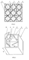
- a fuel assembly 1 comprises spacing grids 2 that are arranged along the length of the assembly 1 downstream a coolant flow.
- the spacing grids 2 comprise cells 3 formed by orthogonal crossing plates 4.
- Each cell 3, through which a fuel rod 5 passes, has an insertable spacing element 6 embracing the fuel rod 5 and designed for fixing the fuel rod 5 passing through the cell 3.
- In the spacing grids that are arranged between the first spacing grid 7 and the last spacing grid 8 downstream the coolant flow at least some cells 3, through which the fuel rods 5 pass, are provided with deflectors 9 designed for mixing the coolant flow.
- the deflectors 9 are made on the crossing plates 4 in the form of bent vanes 10.
- the length L of a cell 3 in the direction of its longitudinal axis is selected in the range from 15 mm to 60 mm.
- a size of the insertable spacing element 6 along the length L of a cell is in the range from 5 mm to 20 mm.
- the insertable spacing element 6 has a closed contour and may be made by pressing from a tube blank.
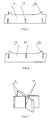
- the insertable spacing element 6 comprises a shell 11, which has a cross section in the form of an octagon formed by four facets 12 that are rounded and convex in the direction from the center of said element and by four facets 13 located therebetween that are shaped and concave toward the center of the said element.
- the convex facets 12 are designed for connection to a spacing grid cell, and the concave facets 13 are designed for fixing a fuel rod.
- the radius R of convex facet rounding is from 8.5 mm to 11 mm.
- the concave facets 13 have a straight section 14, which length h is from 0.5 mm to 1.1 mm, in their central parts.
- the cells 3 are formed by mutually arranging the plates (strips) 4 in the slots 15. For this the length of the strip should be at least one half of the width of the strip.
- the slots 15 on the orthogonally located plates (strips) 4 are oriented toward opposite directions.
- the fuel assembly also comprises the top nozzle 16, the bottom nozzle 17, the central tube 18 and the guide tubes 19.
- the fuel assembly according to this invention works as follows. A coolant passes through the cells 3 and washes the surfaces of the fuel rods 5 located in the cells. At the exit from the cell 3 the coolant interacts with the vanes 10, which results in its mixing and, accordingly, in equalizing its temperature over the cross-section of the fuel assembly.
- the fuel assembly and the insertable spacing element (insert) according to this invention may be made by any known method with the use of standard technologies and equipment and do not require creation of principally new tools.
Landscapes
- Physics & Mathematics (AREA)
- Engineering & Computer Science (AREA)
- Plasma & Fusion (AREA)
- General Engineering & Computer Science (AREA)
- High Energy & Nuclear Physics (AREA)
- Fuel Cell (AREA)
- Fuel-Injection Apparatus (AREA)
- Separation Using Semi-Permeable Membranes (AREA)
- Liquid Carbonaceous Fuels (AREA)
Applications Claiming Priority (2)
| Application Number | Priority Date | Filing Date | Title |
|---|---|---|---|
| RU2006145699/06A RU2331119C1 (ru) | 2006-12-22 | 2006-12-22 | Тепловыделяющая сборка и вставной дистанционирующий элемент |
| PCT/RU2007/000176 WO2008079042A1 (en) | 2006-12-22 | 2007-04-12 | Fuel assembly and and insertable interelement spacer |
Publications (4)
| Publication Number | Publication Date |
|---|---|
| EP1978528A1 true EP1978528A1 (de) | 2008-10-08 |
| EP1978528A4 EP1978528A4 (de) | 2010-06-09 |
| EP1978528B1 EP1978528B1 (de) | 2011-11-09 |
| EP1978528B2 EP1978528B2 (de) | 2015-11-18 |
Family
ID=39562733
Family Applications (1)
| Application Number | Title | Priority Date | Filing Date |
|---|---|---|---|
| EP07793996.5A Active EP1978528B2 (de) | 2006-12-22 | 2007-04-12 | Kraftstoffanordnung und einsetzbare interelementabstandsvorrichtung |
Country Status (7)
| Country | Link |
|---|---|
| US (1) | US7792236B2 (de) |
| EP (1) | EP1978528B2 (de) |
| CN (1) | CN101617373B (de) |
| AT (1) | ATE533163T1 (de) |
| ES (1) | ES2374993T5 (de) |
| RU (1) | RU2331119C1 (de) |
| WO (1) | WO2008079042A1 (de) |
Cited By (1)
| Publication number | Priority date | Publication date | Assignee | Title |
|---|---|---|---|---|
| WO2023099288A1 (de) | 2021-12-02 | 2023-06-08 | Hueck Rheinische Gmbh | Druckausgleichskörper, insbesondere presspolster zur ausrüstung von hydraulischen ein- und mehretagenheiz- und kühlpressen |
Families Citing this family (7)
| Publication number | Priority date | Publication date | Assignee | Title |
|---|---|---|---|---|
| SE530864C2 (sv) * | 2007-02-05 | 2008-09-30 | Westinghouse Electric Sweden | Förfarande för framställning av spridare för kärnreaktor |
| US9020091B2 (en) * | 2008-04-14 | 2015-04-28 | Westinghouse Electric Company Llc | Nuclear fuel assembly with a lock-support spacer grid |
| CN102270511A (zh) * | 2011-07-18 | 2011-12-07 | 中国原子能科学研究院 | 一种压水堆双面冷却燃料棒的管形定位格架 |
| EP2741297A1 (de) * | 2012-12-04 | 2014-06-11 | Areva NP | Brennstab-Stützeinsatz für ein Abstandhaltergitter einer Kernbrennstoffbaugruppe und Kernbrennstoffbaugruppe |
| RU2646597C1 (ru) * | 2016-09-05 | 2018-03-06 | Российская Федерация, от имени которой выступает Государственная корпорация по атомной энергии "Росатом" - Госкорпорация "Росатом" | Твэл реактора на быстрых нейтронах |
| ES2860525T3 (es) * | 2018-12-14 | 2021-10-05 | Framatome Sa | Procedimiento y sistema de ensamblaje para insertar al menos una varilla de combustible nuclear en las rejillas espaciadoras de un conjunto de combustible nuclear |
| EP4016547A1 (de) * | 2020-12-21 | 2022-06-22 | Framatome | Abstandsgitterelement eines abstandsgitters für kernbrennstabbündel, abstandsgitter und kernbrennstabbündel |
Family Cites Families (41)
| Publication number | Priority date | Publication date | Assignee | Title |
|---|---|---|---|---|
| SE327019B (de) * | 1966-12-30 | 1970-08-10 | Asea Ab | |
| US4061536A (en) † | 1966-05-25 | 1977-12-06 | The United States Of America As Represented By The United States Energy Research And Development Administration | Fuel assembly for nuclear reactors |
| US3791466A (en) * | 1969-05-19 | 1974-02-12 | Westinghouse Electric Corp | Low parasitic capture fuel assembly structure |
| US3753855A (en) † | 1970-06-15 | 1973-08-21 | United Nuclear Corp | Modular fuel rod spacer assembly for nuclear reactor fuel assemblies |
| US3787286A (en) * | 1971-12-17 | 1974-01-22 | Combustion Eng | Fuel assembly flow redistribution |
| US3984284A (en) * | 1973-08-03 | 1976-10-05 | Exxon Nuclear Company, Inc. | Spacer capture system for nuclear fuel assemblies |
| US4081324A (en) * | 1976-06-17 | 1978-03-28 | Exxon Nuclear Company Inc. | Spacer capture rod to spacer grid attachment device |
| FR2474229B1 (fr) * | 1980-01-22 | 1986-08-22 | Commissariat Energie Atomique | Grille entretoise pour assemblage combustible de reacteur nucleaire |
| US4585616A (en) | 1983-03-09 | 1986-04-29 | Westinghouse Electric Corp. | Nuclear fuel spacer grid with improved outer straps |
| US4692303A (en) * | 1984-08-23 | 1987-09-08 | Exxon Nuclear Company, Inc. | Spacer capture rod to space grid attachment device |
| FR2577343B1 (fr) * | 1985-02-08 | 1991-03-22 | Commissariat Energie Atomique | Dispositif d'espacement et de maintien de crayons combustibles dans un assemblage combustible |
| DE8503766U1 (de) * | 1985-02-11 | 1988-05-26 | Siemens AG, 1000 Berlin und 8000 München | Kernreaktorbrennelement |
| US4879090A (en) * | 1987-08-24 | 1989-11-07 | Combustion Engineering, Inc. | Split vaned nuclear fuel assembly grid |
| DE3821666C3 (de) * | 1988-06-28 | 1995-02-09 | Bbc Reaktor Gmbh | Halteelement zur Reparatur eines an der Peripherie eines Abstandshalters beschädigten Kernreaktorbrennelements |
| US5032351A (en) * | 1990-05-11 | 1991-07-16 | General Electric Company | Modified cross point spacer apparatus and construction |
| SE503441C2 (sv) * | 1990-10-18 | 1996-06-17 | Asea Atom Ab | Förfarande och anordning för reglering av kylflöde i en tryckvattenreaktors bränslepatron |
| US5089221A (en) * | 1990-10-25 | 1992-02-18 | General Electric Company | Composite spacer with Inconel grid and Zircaloy band |
| US5186891A (en) * | 1991-05-17 | 1993-02-16 | General Electric Company | Swirl vanes in inconel spacer |
| US5327470A (en) * | 1992-02-07 | 1994-07-05 | General Electric Company | Spacer with steam separator |
| EP0573899B1 (de) | 1992-06-10 | 1996-04-24 | Siemens Aktiengesellschaft | Brennelement eines Kernreaktors mit einer Gitterstruktur zur Drallerzeugung |
| US5243635A (en) | 1992-09-25 | 1993-09-07 | Combustion Engineering, Inc. | Fuel rod capturing grid spring and arch |
| FI934540A0 (fi) * | 1992-10-29 | 1993-10-14 | Westinghouse Electric Corp | Braenslemontering, som omfattar avlaenkningskivor foer att leda en komponent av ett floede foerbi braenslemonteringen |
| US5361288A (en) * | 1993-08-16 | 1994-11-01 | General Electric Company | Spacer with integral zircaloy springs |
| JP3121972B2 (ja) † | 1993-12-03 | 2001-01-09 | 三菱原子燃料株式会社 | 核燃料集合体 |
| US5440599A (en) | 1994-02-03 | 1995-08-08 | Combustion Engineering, Inc. | Spacer grid with integral "side supported" flow directing vanes |
| SE503776C2 (sv) | 1994-12-21 | 1996-09-02 | Asea Atom Ab | Bränslepatron och spridare för en kärnreaktor |
| SE504486C2 (sv) * | 1995-06-12 | 1997-02-17 | Asea Atom Ab | Spridare vid en bränslepatron och en bränslepatron |
| SE506149C2 (sv) * | 1996-05-02 | 1997-11-17 | Asea Atom Ab | Spridare för en kärnbränslepatron och en kärnbränslepatron |
| WO1998032133A1 (de) * | 1997-01-15 | 1998-07-23 | Siemens Aktiengesellschaft | Abstandhalter mit befestigten federn für brennelemente von kernreaktoren |
| GB9707690D0 (en) * | 1997-04-16 | 1997-06-04 | British Nuclear Fuels Plc | Improvements in or relating to fuel assemblies |
| US6526116B1 (en) * | 1997-07-02 | 2003-02-25 | Westinghouse Electric Company Llc | Nuclear fuel assembly with hydraulically balanced mixing vanes |
| RU2124239C1 (ru) * | 1997-10-22 | 1998-12-27 | Открытое акционерное общество "Машиностроительный завод" | Дистанционирующая решетка для тепловыделяющей сборки |
| KR100287278B1 (ko) * | 1998-02-04 | 2001-04-16 | 장인순 | 회전유동발생장치를가진핵연료집합체지지격자 |
| KR100368071B1 (ko) * | 2000-03-31 | 2003-01-15 | 한국전력공사 | 핵연료다발 냉각재 혼합 증진을 위한 엇갈림 전향날개 |
| SE519517C2 (sv) * | 2000-07-03 | 2003-03-11 | Westinghouse Atom Ab | Bränslepatron för en nukleär reaktor anordnad med flödespåverkande spridare |
| DE10122489A1 (de) † | 2001-05-09 | 2002-11-28 | Framatome Anp Gmbh | Abstandhalter in einem Brennelement für einen Kernreaktor |
| DE20114248U1 (de) * | 2001-08-29 | 2001-12-13 | Framatome ANP GmbH, 91058 Erlangen | Abstandhalter in einem Brennelement eines Kernreaktors |
| SE526381C2 (sv) | 2004-01-15 | 2005-09-06 | Westinghouse Electric Sweden | Spridare och bränsleenhet för en nukleär anläggning |
| ES2336338T3 (es) * | 2004-01-15 | 2010-04-12 | Westinghouse Electric Sweden Ab | Separador y unidad de combustible para una central nuclear. |
| US8374308B2 (en) | 2005-01-11 | 2013-02-12 | Westinghouse Electric Company Llc | Helically fluted tubular fuel rod support |
| RU2290707C1 (ru) * | 2005-07-08 | 2006-12-27 | Открытое акционерное общество "ТВЭЛ" | Дистанционирующая решетка |
-
2006
- 2006-12-22 RU RU2006145699/06A patent/RU2331119C1/ru active
-
2007
- 2007-04-12 EP EP07793996.5A patent/EP1978528B2/de active Active
- 2007-04-12 US US12/278,773 patent/US7792236B2/en active Active
- 2007-04-12 CN CN2007800477517A patent/CN101617373B/zh active Active
- 2007-04-12 ES ES07793996.5T patent/ES2374993T5/es active Active
- 2007-04-12 AT AT07793996T patent/ATE533163T1/de active
- 2007-04-12 WO PCT/RU2007/000176 patent/WO2008079042A1/ru not_active Ceased
Cited By (1)
| Publication number | Priority date | Publication date | Assignee | Title |
|---|---|---|---|---|
| WO2023099288A1 (de) | 2021-12-02 | 2023-06-08 | Hueck Rheinische Gmbh | Druckausgleichskörper, insbesondere presspolster zur ausrüstung von hydraulischen ein- und mehretagenheiz- und kühlpressen |
Also Published As
| Publication number | Publication date |
|---|---|
| EP1978528B1 (de) | 2011-11-09 |
| US7792236B2 (en) | 2010-09-07 |
| ATE533163T1 (de) | 2011-11-15 |
| WO2008079042A1 (en) | 2008-07-03 |
| ES2374993T5 (es) | 2016-03-08 |
| CN101617373B (zh) | 2013-08-21 |
| EP1978528A4 (de) | 2010-06-09 |
| RU2331119C1 (ru) | 2008-08-10 |
| ES2374993T3 (es) | 2012-02-23 |
| EP1978528B2 (de) | 2015-11-18 |
| CN101617373A (zh) | 2009-12-30 |
| US20090067566A1 (en) | 2009-03-12 |
Similar Documents
| Publication | Publication Date | Title |
|---|---|---|
| EP1978528B1 (de) | Kraftstoffanordnung und einsetzbare interelementabstandsvorrichtung | |
| US6393087B1 (en) | Duct-type spacer grid with swirl flow vanes for nuclear fuel assemblies | |
| EP1679722A1 (de) | Spiralig gerillte röhrenförmige Stütze für Brennstäbe | |
| KR20150093682A (ko) | 핵연료 집합체 스페이서 그리드용 연료봉 지지 인서트, 스페이서 그리드 및 핵연료 집합체 | |
| EP0399182A1 (de) | Abstandshalter mit integrierter, geneigter Wellenstruktur | |
| US6744843B2 (en) | Side-slotted nozzle type double sheet spacer grid for nuclear fuel assemblies | |
| US6721384B2 (en) | Spacer grid with side welding support and flow mixing vane for nuclear reactor fuel assembly | |
| US7804930B2 (en) | Nuclear fuel assembly comprising a reinforcing mesh device and the use of one such device in a nuclear fuel assembly | |
| US6385271B2 (en) | Nuclear fuel assembly | |
| CN1860554B (zh) | 包含内部加强装置的核燃料组件 | |
| CN103548090B (zh) | 核燃料组件连接板、包括该连接板的上部管嘴和核燃料组件 | |
| US6714619B2 (en) | Spacer grid with double deflected vanes for nuclear fuel assemblies | |
| US8358733B2 (en) | Helically fluted tubular fuel rod support | |
| US8009792B2 (en) | Distance lattice for fuel rod assembly in nuclear reactor | |
| KR102939021B1 (ko) | 강화 장치를 구비하는 핵연료 집합체 | |
| KR101071288B1 (ko) | 내부 격자판의 교차영역에서 핵연료봉을 지지하며 상하로 이동 가능한 탄성 지지판과 삽입형 충격 지지판으로 구성된 지지격자체 | |
| JP4416970B2 (ja) | 燃料スペーサ及び燃料集合体 | |
| EP4264636B1 (de) | Abstandsgitterelement eines abstandsgitters für kernbrennstabbündel, abstandsgitter und kernbrennstabbündel | |
| RU2293378C1 (ru) | Дистанционирующая решетка тепловыделяющей сборки ядерного реактора | |
| US6332012B1 (en) | Grid strap for a nuclear fuel assembly, and a grid including such straps | |
| KR20110011275A (ko) | 내부 격자판의 교차영역에서 핵연료봉을 지지하며 상하로 이동가능한 탄성 지지판이 삽입된 지지격자체 | |
| KR101062786B1 (ko) | 핵연료봉의 지지격자체 | |
| JP5972644B2 (ja) | スペーサ |
Legal Events
| Date | Code | Title | Description |
|---|---|---|---|
| PUAI | Public reference made under article 153(3) epc to a published international application that has entered the european phase |
Free format text: ORIGINAL CODE: 0009012 |
|
| 17P | Request for examination filed |
Effective date: 20080731 |
|
| AK | Designated contracting states |
Kind code of ref document: A1 Designated state(s): AT BE BG CH CY CZ DE DK EE ES FI FR GB GR HU IE IS IT LI LT LU LV MC MT NL PL PT RO SE SI SK TR |
|
| AX | Request for extension of the european patent |
Extension state: AL BA HR MK RS |
|
| A4 | Supplementary search report drawn up and despatched |
Effective date: 20100507 |
|
| 17Q | First examination report despatched |
Effective date: 20100923 |
|
| GRAP | Despatch of communication of intention to grant a patent |
Free format text: ORIGINAL CODE: EPIDOSNIGR1 |
|
| DAX | Request for extension of the european patent (deleted) | ||
| RIN1 | Information on inventor provided before grant (corrected) |
Inventor name: DOLGOV, ALEKSEY BORISOVICH Inventor name: USTIMENKO, ALEKSANDR PAVLOVICH Inventor name: ENIN, ANATOLY ALEKSEEVICH Inventor name: SAMOILOV, OLEG BORISOVICH Inventor name: NEKHODA, MIKHAIL MIKHAILOVICH Inventor name: SHUSTOV, MSTISLAV ALEKSANDROVICH Inventor name: TROYANOV, VLADIMIR MIKHAILOVICH Inventor name: KISLITSKY, ALEKSANDR ANTONOVICH Inventor name: ROZHKOV, VLADIMIR VLADIMIROVICH Inventor name: LAVRENYUK, PETR IVANOVICH |
|
| GRAS | Grant fee paid |
Free format text: ORIGINAL CODE: EPIDOSNIGR3 |
|
| GRAA | (expected) grant |
Free format text: ORIGINAL CODE: 0009210 |
|
| AK | Designated contracting states |
Kind code of ref document: B1 Designated state(s): AT BE BG CH CY CZ DE DK EE ES FI FR GB GR HU IE IS IT LI LT LU LV MC MT NL PL PT RO SE SI SK TR |
|
| REG | Reference to a national code |
Ref country code: GB Ref legal event code: FG4D |
|
| REG | Reference to a national code |
Ref country code: CH Ref legal event code: EP |
|
| REG | Reference to a national code |
Ref country code: IE Ref legal event code: FG4D |
|
| REG | Reference to a national code |
Ref country code: CH Ref legal event code: NV Representative=s name: TROESCH SCHEIDEGGER WERNER AG |
|
| REG | Reference to a national code |
Ref country code: DE Ref legal event code: R096 Ref document number: 602007018637 Country of ref document: DE Effective date: 20120105 |
|
| REG | Reference to a national code |
Ref country code: SE Ref legal event code: TRGR |
|
| REG | Reference to a national code |
Ref country code: NL Ref legal event code: VDEP Effective date: 20111109 |
|
| REG | Reference to a national code |
Ref country code: ES Ref legal event code: FG2A Ref document number: 2374993 Country of ref document: ES Kind code of ref document: T3 Effective date: 20120223 |
|
| LTIE | Lt: invalidation of european patent or patent extension |
Effective date: 20111109 |
|
| PG25 | Lapsed in a contracting state [announced via postgrant information from national office to epo] |
Ref country code: IS Free format text: LAPSE BECAUSE OF FAILURE TO SUBMIT A TRANSLATION OF THE DESCRIPTION OR TO PAY THE FEE WITHIN THE PRESCRIBED TIME-LIMIT Effective date: 20120309 Ref country code: LT Free format text: LAPSE BECAUSE OF FAILURE TO SUBMIT A TRANSLATION OF THE DESCRIPTION OR TO PAY THE FEE WITHIN THE PRESCRIBED TIME-LIMIT Effective date: 20111109 |
|
| PG25 | Lapsed in a contracting state [announced via postgrant information from national office to epo] |
Ref country code: PT Free format text: LAPSE BECAUSE OF FAILURE TO SUBMIT A TRANSLATION OF THE DESCRIPTION OR TO PAY THE FEE WITHIN THE PRESCRIBED TIME-LIMIT Effective date: 20120309 Ref country code: SI Free format text: LAPSE BECAUSE OF FAILURE TO SUBMIT A TRANSLATION OF THE DESCRIPTION OR TO PAY THE FEE WITHIN THE PRESCRIBED TIME-LIMIT Effective date: 20111109 Ref country code: PL Free format text: LAPSE BECAUSE OF FAILURE TO SUBMIT A TRANSLATION OF THE DESCRIPTION OR TO PAY THE FEE WITHIN THE PRESCRIBED TIME-LIMIT Effective date: 20111109 Ref country code: NL Free format text: LAPSE BECAUSE OF FAILURE TO SUBMIT A TRANSLATION OF THE DESCRIPTION OR TO PAY THE FEE WITHIN THE PRESCRIBED TIME-LIMIT Effective date: 20111109 Ref country code: GR Free format text: LAPSE BECAUSE OF FAILURE TO SUBMIT A TRANSLATION OF THE DESCRIPTION OR TO PAY THE FEE WITHIN THE PRESCRIBED TIME-LIMIT Effective date: 20120210 Ref country code: LV Free format text: LAPSE BECAUSE OF FAILURE TO SUBMIT A TRANSLATION OF THE DESCRIPTION OR TO PAY THE FEE WITHIN THE PRESCRIBED TIME-LIMIT Effective date: 20111109 |
|
| PG25 | Lapsed in a contracting state [announced via postgrant information from national office to epo] |
Ref country code: CY Free format text: LAPSE BECAUSE OF FAILURE TO SUBMIT A TRANSLATION OF THE DESCRIPTION OR TO PAY THE FEE WITHIN THE PRESCRIBED TIME-LIMIT Effective date: 20111109 |
|
| PG25 | Lapsed in a contracting state [announced via postgrant information from national office to epo] |
Ref country code: SK Free format text: LAPSE BECAUSE OF FAILURE TO SUBMIT A TRANSLATION OF THE DESCRIPTION OR TO PAY THE FEE WITHIN THE PRESCRIBED TIME-LIMIT Effective date: 20111109 Ref country code: DK Free format text: LAPSE BECAUSE OF FAILURE TO SUBMIT A TRANSLATION OF THE DESCRIPTION OR TO PAY THE FEE WITHIN THE PRESCRIBED TIME-LIMIT Effective date: 20111109 Ref country code: EE Free format text: LAPSE BECAUSE OF FAILURE TO SUBMIT A TRANSLATION OF THE DESCRIPTION OR TO PAY THE FEE WITHIN THE PRESCRIBED TIME-LIMIT Effective date: 20111109 Ref country code: BG Free format text: LAPSE BECAUSE OF FAILURE TO SUBMIT A TRANSLATION OF THE DESCRIPTION OR TO PAY THE FEE WITHIN THE PRESCRIBED TIME-LIMIT Effective date: 20120209 |
|
| PLBI | Opposition filed |
Free format text: ORIGINAL CODE: 0009260 |
|
| PG25 | Lapsed in a contracting state [announced via postgrant information from national office to epo] |
Ref country code: IT Free format text: LAPSE BECAUSE OF FAILURE TO SUBMIT A TRANSLATION OF THE DESCRIPTION OR TO PAY THE FEE WITHIN THE PRESCRIBED TIME-LIMIT Effective date: 20111109 Ref country code: RO Free format text: LAPSE BECAUSE OF FAILURE TO SUBMIT A TRANSLATION OF THE DESCRIPTION OR TO PAY THE FEE WITHIN THE PRESCRIBED TIME-LIMIT Effective date: 20111109 |
|
| 26 | Opposition filed |
Opponent name: AREVA NP Effective date: 20120803 |
|
| REG | Reference to a national code |
Ref country code: AT Ref legal event code: MK05 Ref document number: 533163 Country of ref document: AT Kind code of ref document: T Effective date: 20111109 |
|
| PLAX | Notice of opposition and request to file observation + time limit sent |
Free format text: ORIGINAL CODE: EPIDOSNOBS2 |
|
| REG | Reference to a national code |
Ref country code: DE Ref legal event code: R026 Ref document number: 602007018637 Country of ref document: DE Effective date: 20120803 |
|
| PG25 | Lapsed in a contracting state [announced via postgrant information from national office to epo] |
Ref country code: MC Free format text: LAPSE BECAUSE OF NON-PAYMENT OF DUE FEES Effective date: 20120430 |
|
| PGFP | Annual fee paid to national office [announced via postgrant information from national office to epo] |
Ref country code: DE Payment date: 20120822 Year of fee payment: 6 |
|
| REG | Reference to a national code |
Ref country code: IE Ref legal event code: MM4A |
|
| PG25 | Lapsed in a contracting state [announced via postgrant information from national office to epo] |
Ref country code: AT Free format text: LAPSE BECAUSE OF FAILURE TO SUBMIT A TRANSLATION OF THE DESCRIPTION OR TO PAY THE FEE WITHIN THE PRESCRIBED TIME-LIMIT Effective date: 20111109 Ref country code: IE Free format text: LAPSE BECAUSE OF NON-PAYMENT OF DUE FEES Effective date: 20120412 |
|
| PLBB | Reply of patent proprietor to notice(s) of opposition received |
Free format text: ORIGINAL CODE: EPIDOSNOBS3 |
|
| PG25 | Lapsed in a contracting state [announced via postgrant information from national office to epo] |
Ref country code: FI Free format text: LAPSE BECAUSE OF FAILURE TO SUBMIT A TRANSLATION OF THE DESCRIPTION OR TO PAY THE FEE WITHIN THE PRESCRIBED TIME-LIMIT Effective date: 20111109 |
|
| PG25 | Lapsed in a contracting state [announced via postgrant information from national office to epo] |
Ref country code: MT Free format text: LAPSE BECAUSE OF FAILURE TO SUBMIT A TRANSLATION OF THE DESCRIPTION OR TO PAY THE FEE WITHIN THE PRESCRIBED TIME-LIMIT Effective date: 20111109 |
|
| PG25 | Lapsed in a contracting state [announced via postgrant information from national office to epo] |
Ref country code: DE Free format text: LAPSE BECAUSE OF NON-PAYMENT OF DUE FEES Effective date: 20131101 |
|
| REG | Reference to a national code |
Ref country code: DE Ref legal event code: R119 Ref document number: 602007018637 Country of ref document: DE Effective date: 20131101 |
|
| PG25 | Lapsed in a contracting state [announced via postgrant information from national office to epo] |
Ref country code: TR Free format text: LAPSE BECAUSE OF FAILURE TO SUBMIT A TRANSLATION OF THE DESCRIPTION OR TO PAY THE FEE WITHIN THE PRESCRIBED TIME-LIMIT Effective date: 20111109 |
|
| PG25 | Lapsed in a contracting state [announced via postgrant information from national office to epo] |
Ref country code: LU Free format text: LAPSE BECAUSE OF NON-PAYMENT OF DUE FEES Effective date: 20120412 |
|
| APBM | Appeal reference recorded |
Free format text: ORIGINAL CODE: EPIDOSNREFNO |
|
| APBP | Date of receipt of notice of appeal recorded |
Free format text: ORIGINAL CODE: EPIDOSNNOA2O |
|
| APAH | Appeal reference modified |
Free format text: ORIGINAL CODE: EPIDOSCREFNO |
|
| PG25 | Lapsed in a contracting state [announced via postgrant information from national office to epo] |
Ref country code: HU Free format text: LAPSE BECAUSE OF FAILURE TO SUBMIT A TRANSLATION OF THE DESCRIPTION OR TO PAY THE FEE WITHIN THE PRESCRIBED TIME-LIMIT Effective date: 20070412 |
|
| APBU | Appeal procedure closed |
Free format text: ORIGINAL CODE: EPIDOSNNOA9O |
|
| REG | Reference to a national code |
Ref country code: FR Ref legal event code: PLFP Year of fee payment: 9 |
|
| PUAH | Patent maintained in amended form |
Free format text: ORIGINAL CODE: 0009272 |
|
| STAA | Information on the status of an ep patent application or granted ep patent |
Free format text: STATUS: PATENT MAINTAINED AS AMENDED |
|
| 27A | Patent maintained in amended form |
Effective date: 20151118 |
|
| AK | Designated contracting states |
Kind code of ref document: B2 Designated state(s): AT BE BG CH CY CZ DE DK EE ES FI FR GB GR HU IE IS IT LI LT LU LV MC MT NL PL PT RO SE SI SK TR |
|
| REG | Reference to a national code |
Ref country code: DE Ref legal event code: R102 Ref document number: 602007018637 Country of ref document: DE |
|
| REG | Reference to a national code |
Ref country code: CH Ref legal event code: AELC |
|
| REG | Reference to a national code |
Ref country code: SE Ref legal event code: RPEO Ref country code: ES Ref legal event code: DC2A Ref document number: 2374993 Country of ref document: ES Kind code of ref document: T5 Effective date: 20160308 |
|
| REG | Reference to a national code |
Ref country code: FR Ref legal event code: PLFP Year of fee payment: 10 |
|
| REG | Reference to a national code |
Ref country code: FR Ref legal event code: PLFP Year of fee payment: 11 |
|
| REG | Reference to a national code |
Ref country code: FR Ref legal event code: PLFP Year of fee payment: 12 |
|
| PGFP | Annual fee paid to national office [announced via postgrant information from national office to epo] |
Ref country code: ES Payment date: 20250529 Year of fee payment: 19 Ref country code: GB Payment date: 20250429 Year of fee payment: 19 |
|
| PGFP | Annual fee paid to national office [announced via postgrant information from national office to epo] |
Ref country code: BE Payment date: 20250429 Year of fee payment: 19 |
|
| PGFP | Annual fee paid to national office [announced via postgrant information from national office to epo] |
Ref country code: FR Payment date: 20250429 Year of fee payment: 19 |
|
| PGFP | Annual fee paid to national office [announced via postgrant information from national office to epo] |
Ref country code: CH Payment date: 20250508 Year of fee payment: 19 |
|
| PGFP | Annual fee paid to national office [announced via postgrant information from national office to epo] |
Ref country code: CZ Payment date: 20250417 Year of fee payment: 19 |
|
| PGFP | Annual fee paid to national office [announced via postgrant information from national office to epo] |
Ref country code: SE Payment date: 20250429 Year of fee payment: 19 |