EP1978532B1 - Dispositif de réglage électromagnétique - Google Patents
Dispositif de réglage électromagnétique Download PDFInfo
- Publication number
- EP1978532B1 EP1978532B1 EP08004375.5A EP08004375A EP1978532B1 EP 1978532 B1 EP1978532 B1 EP 1978532B1 EP 08004375 A EP08004375 A EP 08004375A EP 1978532 B1 EP1978532 B1 EP 1978532B1
- Authority
- EP
- European Patent Office
- Prior art keywords
- housing
- designed
- accordance
- stop element
- section
- Prior art date
- Legal status (The legal status is an assumption and is not a legal conclusion. Google has not performed a legal analysis and makes no representation as to the accuracy of the status listed.)
- Ceased
Links
Images


Classifications
-
- H—ELECTRICITY
- H01—ELECTRIC ELEMENTS
- H01F—MAGNETS; INDUCTANCES; TRANSFORMERS; SELECTION OF MATERIALS FOR THEIR MAGNETIC PROPERTIES
- H01F7/00—Magnets
- H01F7/06—Electromagnets; Actuators including electromagnets
- H01F7/08—Electromagnets; Actuators including electromagnets with armatures
- H01F7/16—Rectilinearly-movable armatures
- H01F7/1607—Armatures entering the winding
-
- F—MECHANICAL ENGINEERING; LIGHTING; HEATING; WEAPONS; BLASTING
- F16—ENGINEERING ELEMENTS AND UNITS; GENERAL MEASURES FOR PRODUCING AND MAINTAINING EFFECTIVE FUNCTIONING OF MACHINES OR INSTALLATIONS; THERMAL INSULATION IN GENERAL
- F16K—VALVES; TAPS; COCKS; ACTUATING-FLOATS; DEVICES FOR VENTING OR AERATING
- F16K31/00—Actuating devices; Operating means; Releasing devices
- F16K31/02—Actuating devices; Operating means; Releasing devices electric; magnetic
- F16K31/06—Actuating devices; Operating means; Releasing devices electric; magnetic using a magnet, e.g. diaphragm valves, cutting off by means of a liquid
- F16K31/0675—Electromagnet aspects, e.g. electric supply therefor
-
- H—ELECTRICITY
- H01—ELECTRIC ELEMENTS
- H01F—MAGNETS; INDUCTANCES; TRANSFORMERS; SELECTION OF MATERIALS FOR THEIR MAGNETIC PROPERTIES
- H01F7/00—Magnets
- H01F7/06—Electromagnets; Actuators including electromagnets
- H01F7/08—Electromagnets; Actuators including electromagnets with armatures
- H01F7/16—Rectilinearly-movable armatures
- H01F7/1607—Armatures entering the winding
- H01F2007/163—Armatures entering the winding with axial bearing
-
- H—ELECTRICITY
- H01—ELECTRIC ELEMENTS
- H01F—MAGNETS; INDUCTANCES; TRANSFORMERS; SELECTION OF MATERIALS FOR THEIR MAGNETIC PROPERTIES
- H01F7/00—Magnets
- H01F7/06—Electromagnets; Actuators including electromagnets
- H01F7/08—Electromagnets; Actuators including electromagnets with armatures
- H01F7/121—Guiding or setting position of armatures, e.g. retaining armatures in their end position
Definitions
- the present invention relates to an electromagnetic actuator according to the preamble of the main claim.
- an electromagnetic actuator according to the preamble of the main claim.
- Such a device is well known in the art, the Fig. 6 internal state of the art represented, however, was used as generic and demarcating.
- the sectional view of the Fig. 6 a typically designed to actuate a hydraulic or pneumatic valve as a control partner electromagnetic actuator having a guided in a housing 10, formed from an anchor body 12 and a thereto anchoring anchor tappet 14 anchor unit. With his left-side engagement end of the anchor plunger 14 actuates the control partner.
- the emergency hand ram typically as a turned part manufactured
- a stop element 20 is centered in a stop element 20 (sealingly by means of inner ring seal 22), wherein the stop element 22 (which in turn is sealed by an outer ring seal 24 against a hollow cylindrical housing inner wall of the housing 10 and by means of a crimp-on 26 of the housing end, which in an annular groove 28 engages in the element 20, inextricably attached to the housing) is realized as a rotating part.
- the rotary member 20 has at its end a suitably applied external thread 30, which cooperates with a (in the Fig. 6 not shown) is provided with which then, for example, the arrangement shown can be suitably attached or clamped at a site.
- the device shown has numerous disadvantages, which prove to be unfavorable and in need of improvement, especially with regard to cheap mass production technology: So initially the design of the hand-ram 16 and the stroke-limiting stop member 20 is inherently complicated as a turned parts and thus costly.
- the arrangement shown with respect to an internal pressure or fluid compensation (especially regarding in the arrangement flowing oil) is disadvantageous: such as in the sectional view of Fig.
- An electromagnetic actuator according to the preamble of claim 1 is known from DE 43 43 879 A1 or from the US-A-4 054 854 known.
- the object of the present invention is to overcome the weak points shown, in particular to improve the mechanical realization of the end provided in the housing stop element, in conjunction with the hand tappet unit, and in addition to optimize the fluid (oil) balance in the overall system.
- the stop element is realized in two parts, namely by means of a preferably plastic or the like. Molded part realized stop element and a thus directly interacting disc element, so that between these suitable sealing elements - either directly ansitzend, eg. By injection or the like., Or by inserting about of ring seals - can be maintained.
- An exemplary alternative is to realize the stop element as a one-piece deep-drawn part, which further preferably with suitable grooves, undercuts, heels or the like. may be provided for the provision of (again integrally ansitzenden or separate) sealing portions.
- the odor portion of the armature body and tappet portion formed anchor unit is also the odor portion of the armature body and tappet portion formed anchor unit as a sleeve or the like.
- this element itself with the central plunger space as a fluid guide channel for fluid pressure compensation (eg for oil in the system shown) can serve further education according to additionally on the anchor body a (mounting) flange or collar forms, which is economically simple and elegantly serve as a spacer (spacer) between anchor body and relevant stop position in the housing.
- a (mounting) flange or collar forms which is economically simple and elegantly serve as a spacer (spacer) between anchor body and relevant stop position in the housing.
- the sleeve-shaped ram portion for pressure equalization that an associated, pressure-communicating bore in the anchor body can be advantageously performed centrally or centrally.
- the stop element preferably to be formed as a deep-drawn part The end relative to the housing in such a way that it can cooperate snapping or latching there with a suitable abutment or an undercut, so that in this respect a (in production consuming) flanging or the like. Measure, as known from the prior art, can be omitted; Alternatively, it is provided in the context of the invention to provide such a deep-drawn stop element with a connection section for permanent connection to the housing, for example gluing or welding.
- the present invention provides, in a surprisingly simple and elegant manner, a way of significantly improving the generic generation of electromagnetic positioning devices that are advantageous, in particular, from the production and assembly points of view.
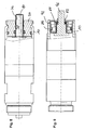
- the first embodiment of the Fig. 1, 2 a plastic stop element 40 as a means for Hubbegrenzung, which is realized as an injection molded part and held against a first annular shoulder 42 in the interior of the housing 10 (in the housing 10 is otherwise, as in connection with Fig. 6 explained, the anchor unit out).
- the plastic stop element 40 cooperates with a disk 44 (made in the present example as a sintered element or stamped part), wherein ring seals 46 are provided between element 40 and 44 both in the area of the outer edge to the housing inner wall and in the region of the inner edge in the direction of the plunger 16 (Outer seal) or 48 (inner seal) are inserted and jammed (alternatively, these seals can also be realized by eg on or injected sealing materials).
- the 3 and 4 show a second embodiment as a variant of in the Fig. 1 and 2 shown first embodiment; as well as there is a union nut 52 formed on an outer peripheral end of the element 40 formed by the housing end protruding external thread 54th
- a stop element 56 as a plastic injection molded part in the end region, immediately adjacent to an upstream in the direction of the anchor (punching) disc 58; in turn, inner and outer annular seals 46, 48 are provided for sealing against the inner housing or a (here purely cylindrical) plunger 60.
- annular shoulder 62 is formed inside the housing.
- FIG. 5 illustrates a variant of the stop element; in the example shown there, the stop is realized by a pair of stamped or sintered discs 64, 66, which in the example shown (favorable for mass production) are configured identically.
- a cross-sectionally on both sides annular shoulder of the elements 64 and 66 serves to receive internal or external ring seals 46, 48, or the interaction with an end paragraph of a (here end protruding) plunger 68.
- Fig. 7 brings a modification of fixing the in Fig. 1 or in Fig. 3 shown union nut 52 (so that the example according to Fig. 7 in principle could be combined with any other embodiments of the present invention).
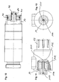
- the function of the union nut takes over a provided with a suitable internal thread yoke disc 72 which rests on an external thread 74 of the housing 10 and is part of the magnetic circuit.
- Fig. 8 illustrates an alternative embodiment of the plunger, in which case a produced as a deep-drawn part plunger 76 forms a sleeve-like portion 78 which forms a circumferential, annular collar 80, whereby the plunger assembly is held in the inner region of the stopper body 20 (shown here is the prerequisite state of the art In principle, however, the configuration of the plunger 76 with any other variant of the stop element according to the present application is possible and conceivable). Not only does this approach make the plunger simpler and less expensive to manufacture and assemble, the collar 18 also creates a distance from the element 20.
- Fig. 9 and 10 show, according to further examples, variants in the design of the stop element.
- a one-piece deep drawn part 82 ( Fig. 9 ) or 84 ( Fig. 10 ) has suitable (eg annular or ring-shaped) recesses 86, 88 and 90 for receiving seals relative to the housing inner surface or the plunger and is on the housing either by means of a resiliently bent latching portion 92 (FIGS. Fig. 9 ), alternatively by means of an annular angled welding flange 94 (FIG. Fig. 10 ).
- the unit 84 In the first case, such a detachable and snap-on device would arise, in the second case, the unit 84 would be permanently connected by gluing or welding at the open end of the housing. In both cases, as can be seen from the figures, a reliable guidance of the respective plunger 96 or 98 is achieved.
- Fig. 11 12 and 12 illustrate another embodiment of the present invention which is similar to that of an anchor block 102 (corresponding to element 32 in FIG Fig. 6 , but with centric center hole 104) anchoring anchor tappet unit 106 as a sleeve (produced by deep-drawing method) forms, such that the open end of the sleeve in the direction of the anchor block extends ring collar shaped to an annular flange 108 which rests on the inside of the housing 10; Thus, the flange thereby forms a spacer to the anchor block 102 which is magnetically effective - can effectively suppress sticking.
- anchor block 102 corresponding to element 32 in FIG Fig. 6 , but with centric center hole 10
- anchoring anchor tappet unit 106 as a sleeve (produced by deep-drawing method) forms, such that the open end of the sleeve in the direction of the anchor block extends ring collar shaped to an annular flange 108 which rests on the inside of the housing 10;
Landscapes
- Physics & Mathematics (AREA)
- Electromagnetism (AREA)
- Engineering & Computer Science (AREA)
- General Engineering & Computer Science (AREA)
- Power Engineering (AREA)
- Mechanical Engineering (AREA)
- Magnetically Actuated Valves (AREA)
Claims (11)
- Dispositif de réglage électromagnétique comprenant une unité d'induit guidée axialement dans un boîtier (10), pouvant être déplacée par l'alimentation d'un dispositif de bobine et en particulier à l'encontre d'une force de rappel d'un ressort de rappel à partir d'une première position de butée déterminée par des moyens de limitation de course,
les moyens de limitation de course présentant un élément de butée (40 ; 56 ; 64 ; 66) fixé du côté de l'extrémité dans le boîtier, fabriqué par un procédé de façonnage, d'estampage, de frittage et/ou de moulage par injection, lequel élément de butée est réalisé de manière à coopérer avec une unité de tige poussoir (16 ; 60 ; 68) pouvant être actionnée depuis l'extérieur du boîtier, prévue pour déplacer mécaniquement l'unité d'induit depuis la première position de butée, et
l'élément de butée étant fabriqué en un matériau non magnétique,
caractérisé en ce que l'élément de butée est réalisé de manière à coopérer avec un élément de rondelle (44 ; 58) de telle sorte qu'entre l'élément de butée et l'élément de rondelle soit retenue une garniture d'étanchéité (48 ; 50) agissant contre une paroi interne du boîtier et/ou contre l'unité de tige poussoir, la garniture d'étanchéité étant réalisée sous forme d'élément séparé ou étant façonnée sur l'élément de butée et/ou sur l'élément de rondelle, l'élément de rondelle étant fabriqué sous forme de pièce estampée, moulée par injection et/ou frittée et l'élément de butée faisant saillie du côté de l'extrémité hors du boîtier et une portion filetée (54) étant réalisée à cet endroit, laquelle est réalisée de manière à coopérer avec un écrou fileté fixant le boîtier sur un lieu d'utilisation. - Dispositif selon la revendication 1, caractérisé en ce que l'élément de butée est fabriqué en matière plastique.
- Dispositif selon l'une quelconque des revendications 1 à 2, caractérisé en ce que l'unité d'induit est réalisée de manière à coopérer avec un élément d'espacement (108) situé entre la première position de butée et une deuxième position de butée opposée à celle-ci, l'élément d'espacement étant réalisé d'une seule pièce avec une portion de tige poussoir (106) de l'unité d'induit du côté de l'engagement.
- Dispositif selon la revendication 3, caractérisé en ce que la portion de tige poussoir est réalisée sous forme allongée et du côté de l'extrémité de manière à coopérer avec une soupape.
- Dispositif selon la revendication 3 ou 4, caractérisé en ce que la portion de tige poussoir est réalisée sous forme de pièce emboutie avec une portion de douille et une portion de col plane servant d'élément d'espacement, s'appliquant du côté frontal contre un corps d'induit de l'unité d'induit.
- Dispositif selon l'une quelconque des revendications 3 à 5, caractérisé par un canal d'équilibrage de lubrifiant, qui est formé par la portion de douille et le corps d'induit cylindrique.
- Dispositif selon l'une quelconque des revendications 1 à 6, caractérisé en ce que l'unité de tige poussoir et/ou l'élément de butée sont réalisés sous forme de pièce emboutie.
- Dispositif selon la revendication 7, caractérisé en ce qu'une portion d'extrémité de l'élément de butée réalisé sous forme de pièce emboutie (82), orientée vers l'extrémité du boîtier, présente une portion d'encliquetage (92) agissant contre un palier de butée.
- Dispositif selon la revendication 7, caractérisé en ce que l'élément de butée (84) réalisé sous forme de pièce emboutie présente du côté de l'extrémité une portion de liaison (94) prévue pour la connexion imperdable avec l'extrémité du boîtier.
- Dispositif selon l'une quelconque des revendications 7 à 9, caractérisé en ce que l'élément de butée réalisé sous forme de pièce emboutie présente une rainure de réception (86, 90) pour une garniture d'étanchéité agissant contre une paroi interne du boîtier et/ou contre l'unité de tige poussoir.
- Dispositif selon l'une quelconque des revendications 1 à 10, caractérisé en ce que le boîtier présente un filetage extérieur (74), qui est réalisé pour coopérer avec un disque de culasse (72) agissant en tant que partie du circuit magnétique du dispositif de réglage électromagnétique, le disque de culasse étant prévu pour fixer en outre le boîtier (10) sur un lieu d'utilisation.
Applications Claiming Priority (1)
| Application Number | Priority Date | Filing Date | Title |
|---|---|---|---|
| DE202007005133U DE202007005133U1 (de) | 2007-04-04 | 2007-04-04 | Elektromagnetische Stellvorrichtung |
Publications (2)
| Publication Number | Publication Date |
|---|---|
| EP1978532A1 EP1978532A1 (fr) | 2008-10-08 |
| EP1978532B1 true EP1978532B1 (fr) | 2013-11-20 |
Family
ID=39370333
Family Applications (1)
| Application Number | Title | Priority Date | Filing Date |
|---|---|---|---|
| EP08004375.5A Ceased EP1978532B1 (fr) | 2007-04-04 | 2008-03-10 | Dispositif de réglage électromagnétique |
Country Status (4)
| Country | Link |
|---|---|
| US (1) | US8362861B2 (fr) |
| EP (1) | EP1978532B1 (fr) |
| CN (1) | CN101409133A (fr) |
| DE (1) | DE202007005133U1 (fr) |
Families Citing this family (5)
| Publication number | Priority date | Publication date | Assignee | Title |
|---|---|---|---|---|
| FR2958981B1 (fr) * | 2010-04-15 | 2012-08-24 | Messier Dowty Sa | Actionneur electromecanique a regulation hydraulique, et atterrisseur equipe d'un tel actionneur pour sa manoeuvre |
| DE102011051268B4 (de) * | 2011-06-22 | 2014-03-06 | Eto Magnetic Gmbh | Elektromagnetische Stellvorrichtung sowie Nockenwellenverstellvorrichtung |
| CN103697216A (zh) * | 2013-12-17 | 2014-04-02 | 宁波华液机器制造有限公司 | 一种低功耗电磁阀 |
| CN104315229B (zh) * | 2014-10-20 | 2016-09-14 | 宁波市鄞州通力液压电器厂 | 电磁阀用电磁铁 |
| US10921013B2 (en) * | 2019-06-27 | 2021-02-16 | Johnson Controls Technology Company | Actuator with stroke displacement setting via a stroke limiting attachment |
Family Cites Families (12)
| Publication number | Priority date | Publication date | Assignee | Title |
|---|---|---|---|---|
| GB1493936A (en) * | 1974-04-04 | 1977-11-30 | Expert Ind Controls Ltd | Valve operator |
| DE3014962A1 (de) * | 1980-04-18 | 1981-10-22 | Binder Magnete Gmbh, 7730 Villingen | Druckdichter einfach-hubmagnet |
| DE8221714U1 (de) * | 1982-07-30 | 1982-09-23 | Robert Bosch Gmbh, 7000 Stuttgart | Elektromagnetischer Schalter, insbesondere für Andrehvorrichtungen von Brennkraftmaschinen |
| FR2544910B1 (fr) * | 1983-04-20 | 1985-06-28 | Outillage Air Comprime | Electroaimant pour courant alternatif a armature mobile dans un tube etanche |
| US4540962A (en) * | 1984-05-29 | 1985-09-10 | General Motors Corporation | Solenoid coil wire termination |
| EP0217969A1 (fr) * | 1985-09-28 | 1987-04-15 | Mannesmann Tally Ges. mbH | Noyau plongeur pour des fréquences jusqu'à 3.000 Hz et plus |
| US4725801A (en) * | 1986-10-24 | 1988-02-16 | Hamilton Standard Controls, Inc. | Bistable solenoid switch |
| US4845451A (en) * | 1987-07-23 | 1989-07-04 | Mitsubishi Mining & Cement Co., Ltd. | Electromagnet |
| DE4343879A1 (de) | 1993-12-08 | 1995-06-14 | Rexroth Mannesmann Gmbh | Elektromagnet, insbesondere für ein hydraulisches Ventil |
| DE19934846A1 (de) * | 1999-07-24 | 2001-01-25 | Hydraulik Ring Gmbh | Elektromagnet und hydraulisches Ventil mit einem Elektromagneten |
| JP2004003599A (ja) * | 2002-03-29 | 2004-01-08 | Denso Corp | 電磁駆動装置 |
| DE102004039800B4 (de) * | 2004-08-17 | 2006-07-27 | Hydraulik-Ring Gmbh | Nockenwellenverstellsystem |
-
2007
- 2007-04-04 DE DE202007005133U patent/DE202007005133U1/de not_active Expired - Lifetime
-
2008
- 2008-03-10 EP EP08004375.5A patent/EP1978532B1/fr not_active Ceased
- 2008-04-03 US US12/062,109 patent/US8362861B2/en not_active Expired - Fee Related
- 2008-04-03 CN CNA200810144689XA patent/CN101409133A/zh active Pending
Also Published As
| Publication number | Publication date |
|---|---|
| DE202007005133U1 (de) | 2008-08-14 |
| CN101409133A (zh) | 2009-04-15 |
| US8362861B2 (en) | 2013-01-29 |
| US20080246568A1 (en) | 2008-10-09 |
| EP1978532A1 (fr) | 2008-10-08 |
Similar Documents
| Publication | Publication Date | Title |
|---|---|---|
| EP1928714B1 (fr) | Electrovanne | |
| EP2158596B1 (fr) | Dispositif de réglage électromagnétique | |
| EP0951412A1 (fr) | Vanne magnetique | |
| EP1967744B1 (fr) | Cylindre hydraulique, en particulier maître-cylindre pour un actionnement d'embrayage ou de frein de véhicule automobile hydraulique, et procédé de fabrication d'un piston correspondant | |
| EP1978532B1 (fr) | Dispositif de réglage électromagnétique | |
| EP1115604B1 (fr) | Electro-valve, notamment destinee au systeme de freinage hydraulique et anti-patinage d'un vehicule | |
| DE102013220557A1 (de) | Ventilanordnung für eine Vorrichtung zum pneumatischen Befüllen und Entleeren von Blasen | |
| DE10218759B4 (de) | Pneumatisches Schieberventil mit einem zweiteiligen Ventilgehäuse aus Kunststoff | |
| EP3175153B1 (fr) | Dispositif d'actionnement hydraulique pour actionner des actionneurs dans une boîte de vitesses de véhicule automobile | |
| DE102004001565A1 (de) | Elektromagnetisches Ventil, insbesondere für eine Bremsanlage eines Kraftfahrzeugs | |
| EP0607370B1 (fr) | Piston a soupape centrale pour systemes hydrauliques de freinage | |
| EP3667130B1 (fr) | Unité de verrouillage pourvue de pièce centrale | |
| DE102019114450A1 (de) | Verriegelungseinheit mit Rohrstück | |
| EP1591856A1 (fr) | Vanne de régulation de pression | |
| DE19810330A1 (de) | Magnetventil | |
| EP1582793B1 (fr) | Vanne électropneumatique | |
| EP1659268A1 (fr) | Poussoir pour moteur à combustion interne | |
| EP3446011B1 (fr) | Dispositif pneumatique à plusieurs soupapes ainsi que procédé de fabrication | |
| EP1998092A2 (fr) | Soupape électropneumatique, en particulier soupape pilote d'un distributeur pneumatique | |
| EP3667129A1 (fr) | Unité de verrouillage pourvu de pièce tubulaire | |
| DE19603384A1 (de) | Befestigungsvorrichtung | |
| DE102005014414A1 (de) | Vorrichtung zur Überwachung von Position und Bewegung eines Bremspedals sowie Montageverfahren hierfür | |
| DE10031873B4 (de) | Hydraulisches Ventil | |
| EP1964134A1 (fr) | Dispositif d'actionnement | |
| WO2008061719A1 (fr) | Électroaimant pour l'actionnement de soupapes |
Legal Events
| Date | Code | Title | Description |
|---|---|---|---|
| PUAI | Public reference made under article 153(3) epc to a published international application that has entered the european phase |
Free format text: ORIGINAL CODE: 0009012 |
|
| AK | Designated contracting states |
Kind code of ref document: A1 Designated state(s): AT BE BG CH CY CZ DE DK EE ES FI FR GB GR HR HU IE IS IT LI LT LU LV MC MT NL NO PL PT RO SE SI SK TR |
|
| AX | Request for extension of the european patent |
Extension state: AL BA MK RS |
|
| 17P | Request for examination filed |
Effective date: 20090328 |
|
| AKX | Designation fees paid |
Designated state(s): DE GB IT |
|
| 17Q | First examination report despatched |
Effective date: 20090616 |
|
| GRAP | Despatch of communication of intention to grant a patent |
Free format text: ORIGINAL CODE: EPIDOSNIGR1 |
|
| INTG | Intention to grant announced |
Effective date: 20130711 |
|
| GRAS | Grant fee paid |
Free format text: ORIGINAL CODE: EPIDOSNIGR3 |
|
| GRAA | (expected) grant |
Free format text: ORIGINAL CODE: 0009210 |
|
| AK | Designated contracting states |
Kind code of ref document: B1 Designated state(s): DE GB IT |
|
| REG | Reference to a national code |
Ref country code: GB Ref legal event code: FG4D Free format text: NOT ENGLISH |
|
| REG | Reference to a national code |
Ref country code: DE Ref legal event code: R096 Ref document number: 502008010966 Country of ref document: DE Effective date: 20140116 |
|
| REG | Reference to a national code |
Ref country code: DE Ref legal event code: R097 Ref document number: 502008010966 Country of ref document: DE |
|
| PLBE | No opposition filed within time limit |
Free format text: ORIGINAL CODE: 0009261 |
|
| STAA | Information on the status of an ep patent application or granted ep patent |
Free format text: STATUS: NO OPPOSITION FILED WITHIN TIME LIMIT |
|
| 26N | No opposition filed |
Effective date: 20140821 |
|
| GBPC | Gb: european patent ceased through non-payment of renewal fee |
Effective date: 20140310 |
|
| REG | Reference to a national code |
Ref country code: DE Ref legal event code: R097 Ref document number: 502008010966 Country of ref document: DE Effective date: 20140821 |
|
| PG25 | Lapsed in a contracting state [announced via postgrant information from national office to epo] |
Ref country code: GB Free format text: LAPSE BECAUSE OF NON-PAYMENT OF DUE FEES Effective date: 20140310 |
|
| REG | Reference to a national code |
Ref country code: DE Ref legal event code: R082 Ref document number: 502008010966 Country of ref document: DE Representative=s name: PATENT- UND RECHTSANWALTSKANZLEI DAUB, DE Ref country code: DE Ref legal event code: R082 Ref document number: 502008010966 Country of ref document: DE Representative=s name: DAUB PARTG MBB, DE |
|
| PGFP | Annual fee paid to national office [announced via postgrant information from national office to epo] |
Ref country code: DE Payment date: 20240321 Year of fee payment: 17 |
|
| PGFP | Annual fee paid to national office [announced via postgrant information from national office to epo] |
Ref country code: IT Payment date: 20240329 Year of fee payment: 17 |
|
| REG | Reference to a national code |
Ref country code: DE Ref legal event code: R119 Ref document number: 502008010966 Country of ref document: DE |
|
| PG25 | Lapsed in a contracting state [announced via postgrant information from national office to epo] |
Ref country code: DE Free format text: LAPSE BECAUSE OF NON-PAYMENT OF DUE FEES Effective date: 20251001 |
|
| PG25 | Lapsed in a contracting state [announced via postgrant information from national office to epo] |
Ref country code: IT Free format text: LAPSE BECAUSE OF NON-PAYMENT OF DUE FEES Effective date: 20250310 |