EP1978534A2 - Clavier pour un appareil ménager et son procédé d'encastrement - Google Patents
Clavier pour un appareil ménager et son procédé d'encastrement Download PDFInfo
- Publication number
- EP1978534A2 EP1978534A2 EP08102700A EP08102700A EP1978534A2 EP 1978534 A2 EP1978534 A2 EP 1978534A2 EP 08102700 A EP08102700 A EP 08102700A EP 08102700 A EP08102700 A EP 08102700A EP 1978534 A2 EP1978534 A2 EP 1978534A2
- Authority
- EP
- European Patent Office
- Prior art keywords
- button
- frame
- keyboard
- locking piece
- knob
- Prior art date
- Legal status (The legal status is an assumption and is not a legal conclusion. Google has not performed a legal analysis and makes no representation as to the accuracy of the status listed.)
- Granted
Links
Images

Classifications
-
- H—ELECTRICITY
- H01—ELECTRIC ELEMENTS
- H01H—ELECTRIC SWITCHES; RELAYS; SELECTORS; EMERGENCY PROTECTIVE DEVICES
- H01H13/00—Switches having rectilinearly-movable operating part or parts adapted for pushing or pulling in one direction only, e.g. push-button switch
- H01H13/70—Switches having rectilinearly-movable operating part or parts adapted for pushing or pulling in one direction only, e.g. push-button switch having a plurality of operating members associated with different sets of contacts, e.g. keyboard
- H01H13/702—Switches having rectilinearly-movable operating part or parts adapted for pushing or pulling in one direction only, e.g. push-button switch having a plurality of operating members associated with different sets of contacts, e.g. keyboard with contacts carried by or formed from layers in a multilayer structure, e.g. membrane switches
- H01H13/705—Switches having rectilinearly-movable operating part or parts adapted for pushing or pulling in one direction only, e.g. push-button switch having a plurality of operating members associated with different sets of contacts, e.g. keyboard with contacts carried by or formed from layers in a multilayer structure, e.g. membrane switches characterised by construction, mounting or arrangement of operating parts, e.g. push-buttons or keys
-
- H—ELECTRICITY
- H02—GENERATION; CONVERSION OR DISTRIBUTION OF ELECTRIC POWER
- H02B—BOARDS, SUBSTATIONS OR SWITCHING ARRANGEMENTS FOR THE SUPPLY OR DISTRIBUTION OF ELECTRIC POWER
- H02B1/00—Frameworks, boards, panels, desks, casings; Details of substations or switching arrangements
- H02B1/015—Boards, panels, desks; Parts thereof or accessories therefor
- H02B1/04—Mounting thereon of switches or of other devices in general, the switch or device having, or being without, casing
- H02B1/044—Mounting through openings
-
- H—ELECTRICITY
- H01—ELECTRIC ELEMENTS
- H01H—ELECTRIC SWITCHES; RELAYS; SELECTORS; EMERGENCY PROTECTIVE DEVICES
- H01H13/00—Switches having rectilinearly-movable operating part or parts adapted for pushing or pulling in one direction only, e.g. push-button switch
- H01H13/02—Details
- H01H13/12—Movable parts; Contacts mounted thereon
- H01H13/14—Operating parts, e.g. push-button
-
- H—ELECTRICITY
- H01—ELECTRIC ELEMENTS
- H01H—ELECTRIC SWITCHES; RELAYS; SELECTORS; EMERGENCY PROTECTIVE DEVICES
- H01H11/00—Apparatus or processes specially adapted for the manufacture of electric switches
- H01H2011/0093—Standardization, e.g. limiting the factory stock by limiting the number of unique, i.e. different components
-
- H—ELECTRICITY
- H01—ELECTRIC ELEMENTS
- H01H—ELECTRIC SWITCHES; RELAYS; SELECTORS; EMERGENCY PROTECTIVE DEVICES
- H01H2217/00—Facilitation of operation; Human engineering
- H01H2217/022—Part of keyboard not operable
-
- H—ELECTRICITY
- H01—ELECTRIC ELEMENTS
- H01H—ELECTRIC SWITCHES; RELAYS; SELECTORS; EMERGENCY PROTECTIVE DEVICES
- H01H2231/00—Applications
- H01H2231/012—Household appliance
Definitions
- the present invention relates to a keyboard for a device, in particular a household appliance, with at least one control element which is arranged in a predetermined position of the control.
- the keyboard has at least one button suitable for operating the control, a frame in which the button is slidably provided in a predetermined position of the button, and a blocking element.
- the invention relates to a method for installing the keyboard in household appliances.
- buttons are arranged on the front.
- the buttons can u.a. be in the style of push, turn, tilt and slide buttons.
- the high-end area has a higher number of functions and controls, ultimately operating buttons of the controls, on than the household appliances of the lower-priced area.
- buttons are part of a keyboard that is built into the device.
- This same front of the control panel can be used for a home appliance of the lowest quality range with a smaller number of controls and consequently a lower number of functionalities of the device. Therefore, this lowest quality device will have fewer buttons to operate the controls.
- the object of the invention is therefore to provide a keyboard for a device with greater versatility, ease of assembly into the device and with lower financial costs than the keyboards of the current state of the art and a method.
- a keyboard for a device having at least one control element which is arranged in a predetermined position of the control element and a keyboard which has at least one button which is used for actuating the Control is suitable; a frame in which the button is slidably providable in a predetermined position of the button; and a blocking member to selectively lock the displaceability of the button permanently in a state where the keyboard is installed in a device and the position of the control and the position of the button differ, or a function of the control by means of button must be excluded; or permanently enable the displaceability of the button, in which the keyboard is mounted in the device and the position of the control and the position of the button correspond to each other and a function of the control by means of button must be enabled.
- the same keyboard can be installed in different devices, depending on the need to activate a control of the device or have a control activated by the button without another element for closing the opening created by the button. to use.
- the blocking element blocks the movement of the button and thus the same button on the keyboard takes over the capping function for closing the opening of the button or in the event that the control is activated, the blocking element is not activated and allows the movement of the knob to its adjustment free space.
- the blocking element can be made effective in any manner, for example, by gluing, by clamping, by vibration welding, casting welding, heating element welding, ultrasonic welding and / or tightening.
- the button is a button that is selected from a group of buttons, with: Push buttons, push buttons, and knobs because a keyboard in a device may have one or more of these button types that may or may not be locked because they do not trigger a control.
- the button is rotatably mounted in the frame, which gives it a support point with respect to the frame of the keyboard and its actuating movement is thus a rotation with respect to a rotation axis of the frame.
- the frame has a frame edge and the button has a button support projection which can rest on the frame edge in a rest position of the button to receive the button in the frame. This ensures a rest position of the button in the frame and that it does not pick up any unwanted movements relative to the frame.
- the frame includes a frame window to lock a control display.
- a control display For example, in the event that the control is to display its functional state or any other information, this may be done by means of the display, which is locked, mounted or attached in any manner, by gluing, by vibration welding, casting welding, hot plate welding, Ultrasonic welding and / or screwing to a frame window of any geometric shape, which consists of one piece or is connected to the frame.
- the blocking element is disposed in the frame and / or in the button. In a manner in which one is connected to the other, or where the relative displacement between the two is prevented, so that the button does not move, even if it should be pressed by the user.
- the blocking element is arranged on the frame back side and / or the back side of the button, being directed towards the interior of the device and being invisible to the user.
- the locking element is arranged on the opposite side of a knob rotation axis, wherein the rotation is blocked around the axis.
- the blocking element is an integral fusible part of the frame and / or the button. This embodiment allows the inclusion of the blocking element in the frame and / or button, wherein the number of parts is reduced.
- the melt shape of the blocking element may be, among others, vibration welding, casting welding, heating element welding, ultrasonic welding.
- the blocking element extends in a molten state on the back of the button and on the back of the frame. Thus, the movement is blocked by the melting of the one-piece fusible part of the frame and / or the button with a light and fast locking system.
- the blocking element has a locking piece. It is a piece that does not belong to the frame and / or knob that can realize blocking the relative movement of the knob.
- the locking piece is a frame-shaped locking piece, which is connectable to the frame window.
- the connection between the two can be made in any manner, such as gluing, stapling, vibration welding, curtain welding, hot plate welding, ultrasonic welding, screwing, the opening of both preferably having the same size to allow visual detection of the control information via the display of the control is possible.
- the frame-shaped locking piece has at least one locking piece portion which protrudes from a locking piece edge of the frame-shaped locking piece to rest on a button support projection, whereby a button displacement distance is locked. Since the locking piece is locked on the frame window, the locking piece portion directly prevents the movement of the button.
- the blocking element extends in a molten state on the Sperr Swiss Wegseite. It is a quick way to block the path of movement of the button by melting the blocking element, connecting it to the back of the button.
- the button and / or the frame and / or the blocking element are made of plastic. It is particularly advantageous for the manufacture of this type of keyboards and for blocking the button by a fusible blocking element, because the melting of the plastic can be carried out at relatively low temperatures and thereby a very reliable blocking is achieved.
- this object is achieved by a method of installing a keyboard according to one or more of claims 1 to 16 in appliances, in particular household appliances, where they themselves have controls or different positions and thereby include the following steps: Keyboard is installed in a device in which the position of the control element and the position of the button differ from each other or exclude a function of the control by the knob: Permanently blocking the mobility of the button by the blocking element; and when the keyboard is installed in the device in which the position of the control and the position of the button coincide and a function of the control by the button is to allow: permitting the mobility of the button to be permanently maintained by leaving the locking element in an unlocked condition becomes.
- the mobility of the button is permanently blocked when the blocking element has melted. This method is very fast and reliable.
- the blocking element can be melted by heat generated by a welding process by vibration or friction.
- the mobility of the button is permanently blocked when the locking piece is secured to the frame so that the locking portion of the locking piece blocks the displacement of the button, the locking piece is connected to the frame or with the frame window, which locks the display of the control simultaneously ,
- the frame part can also be connected to the frame window or to the frame by vibration welding. If the material of which the button, frame and / or locking piece are made is plastic, vibration welding is a very advantageous method.
- FIG. 1 Fig. 3 shows an exploded perspective of a keyboard 1 according to an embodiment of the invention, seen from its rear side.
- the keyboard of the figure has six buttons 30 for actuating the controls 20.
- the buttons 30 are fixed and rotate about axes of rotation of the buttons 34, which are arranged on the frame 40 in each case in a group of three on each side of a frame window 44.
- the buttons 30 on the opposite side of the axis of rotation 34 have a button support projection 36 to accommodate on an edge of the frame 42 when the knob 30 from its installed position of FIG. 1 180 ° in its functional position of the FIG. 2 rotates.
- the button support projections have a groove that surrounds each pin and is very close to, but not touching, thereby allowing the free movement of the knob.
- a control display 22 is arranged to gain access to the information represented by the controls or function of the device.
- a locking piece in the form of a frame 54 is arranged, which is the entire perimeter of the window 44 covered.
- This locking piece in frame form has a locking piece edge 57 from which protrude three locking piece portions 56, which are arranged in wing shape parallel to the window 44 in the direction of the buttons to lock three buttons 30.
- Each locking piece portion 56 has two holes to allow the pins of the locking elements 50 to enter, which, as soon as the locking piece is in frame form in its place on the display 22, protrude from the holes on the back of the locking piece 58.
- the locked buttons would work as in the Fig. 5 is shown, and the three unlocked according to FIG. 4 , Of course, the locked and unlocked buttons depend on the controls of the device; in the high quality could all be activated and the cheaper could all be locked except one.
- FIG. 2 is a perspective of the keyboard 1 according to the embodiment of the invention FIG. 1 shown, which is seen from the back.
- the buttons 30 are mounted on the frame axles 34 and rotated to their operative position.
- the display 22 is disposed on the rectangular frame window 44 enclosing it on its four sides and the locking piece in frame form 54 is on the display 22, forms a sandwich with the display and reliably locks it.
- the locking piece in frame form 54 has been connected to the frame 40 by the vibration welding method, and the pins of the locking member 50 have been simultaneously melted and joined to the locking piece 54, causing locking and locking of the buttons 30.
- the other three buttons remain unlocked and would function as in FIG. 4 is explained.
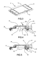
- FIG. 3 shows a perspective of a keyboard 1 according to the inventive embodiment of the preceding figures, which is seen from the front side. Both the buttons 30 and the frame 40 and the display 22 are balanced in an equal plane for aesthetic reasons.
- FIG. 4 shows a cross section of a keyboard 1 according to the inventive embodiment of the preceding figures with the unlocked button 30 in contact with a Control 20.
- the knob is engaged in its functional position on the axis of rotation of the knob 34 and on its opposite side it is supported on the frame edge 42 by the button support projection 36 from.
- the button support projection 36 has a recess which revolves around it and lies very close to the pin of the locking element 50, which is not deformed, goes beyond the back of the locking piece 58 and consequently allows the knob free movement on its Knopfver einsweg 38.
- the locking element 50th is disabled and part of a frame piece 40, as well as the axis of rotation of the knob 34.
- the display of the control element 22 is supported and forms a sandwich with this and, by being locked, the locking piece 50 is arranged can be in the form of a frame or be part of it.
- the button tilts around the knob rotation axis 32 of the frame 40 and the connection to the control element 20 is realized by a changeover contact.
- the changeover contact system accommodates the potential deviations from existing tolerances between the button and the control, thereby ensuring their functionality.
- FIG. 5 shows a cross section of a keyboard 1 according to the inventive embodiment of the preceding figures with the already locked button 30, which has no control to activate.
- the button is locked in the axis of rotation of the knob 34 and on the opposite side it is supported on the frame edge 42 by the button support projection 36 from.
- the button support projection 36 has a recess which orbits it and is located very close to the pin of the locking element 50 which is deformed and protrudes beyond the rear side of the locking piece 58 covering the button support projection 36 as it passes through the opening in the area of the locking piece section 56. whereby it forms a sandwich with him against the frame edge 42 and as a result, the movement of the knob 30 is definitely blocked.
- the blocking element 50 is part of a part of the frame 40 and has been activated by means of vibration welding by means of the melting process.
- the button lock could be realized without locking piece 50 and without locking piece in frame 54. You could simply deform the pin of the locking element 50 on the button support projection 36 while blocking its movement.
- the recess of the button support projection 36 which surrounds the pin of the locking member 50 is very close to, surrounds this largely and when it is deformed by heat, it covers the back of the knob 32.
- the display 22 in this embodiment could be glued to the frame window or locking in any known manner or by melting a projection on the inside of the edge of the frame window is arranged to be connected to the same process of vibration melting, wherein the inside of the display is covered and the display is locked on the frame window in a solid and definitive position.
- buttons and changing the graphics that display their functions can be satisfied by simply locking buttons and changing the graphics that display their functions.
- the keypad which has more than one button on the frame, provides a one-piece bandage that provides the versatility required of such a wide range of different devices through a fitting method appropriate to each type of device. By attaching the keyboard only to a window present in the panel, the adjustment of the buttons to the controls is more reliable than when the display and buttons are each to be fastened separately.
Landscapes
- Engineering & Computer Science (AREA)
- Power Engineering (AREA)
- Push-Button Switches (AREA)
- Input From Keyboards Or The Like (AREA)
- Switch Cases, Indication, And Locking (AREA)
- Slide Switches (AREA)
Applications Claiming Priority (1)
| Application Number | Priority Date | Filing Date | Title |
|---|---|---|---|
| ES200701016A ES2304891B1 (es) | 2007-04-04 | 2007-04-04 | Teclado para un aparato electrodomestico y metodo para instalarlo. |
Publications (3)
| Publication Number | Publication Date |
|---|---|
| EP1978534A2 true EP1978534A2 (fr) | 2008-10-08 |
| EP1978534A3 EP1978534A3 (fr) | 2009-10-28 |
| EP1978534B1 EP1978534B1 (fr) | 2011-06-01 |
Family
ID=39494573
Family Applications (1)
| Application Number | Title | Priority Date | Filing Date |
|---|---|---|---|
| EP08102700A Not-in-force EP1978534B1 (fr) | 2007-04-04 | 2008-03-18 | Clavier pour un appareil ménager et son procédé d'encastrement |
Country Status (3)
| Country | Link |
|---|---|
| EP (1) | EP1978534B1 (fr) |
| AT (1) | ATE511697T1 (fr) |
| ES (1) | ES2304891B1 (fr) |
Cited By (1)
| Publication number | Priority date | Publication date | Assignee | Title |
|---|---|---|---|---|
| WO2009103628A1 (fr) * | 2008-02-20 | 2009-08-27 | Preh Gmbh | Ensemble tableau de commutation avec pièce d’actionnement et pièce de recouvrement fabriquées à partir de la même pièce de base |
Citations (4)
| Publication number | Priority date | Publication date | Assignee | Title |
|---|---|---|---|---|
| EP0435131A1 (fr) | 1989-12-28 | 1991-07-03 | Alcatel Business Systems | Clavier à touches captives |
| US5921381A (en) | 1998-01-06 | 1999-07-13 | Watlow Electric Manufacturing Company | Locking button |
| DE10057402A1 (de) | 1999-11-19 | 2001-05-23 | Bt Ind Ab Mjoelby | Schalteranordnung, insbesondere für Flurförderzeuge |
| DE10250497C1 (de) | 2002-10-29 | 2003-10-30 | Kieback & Peter Gmbh & Co Kg | Drucktasten-Schaltvorrichtung |
Family Cites Families (5)
| Publication number | Priority date | Publication date | Assignee | Title |
|---|---|---|---|---|
| KR100593634B1 (ko) * | 2001-06-22 | 2006-06-30 | 주식회사 엘지이아이 | 가전기기의 콘트롤패널조립체 |
| DE60234827D1 (de) * | 2001-06-22 | 2010-02-04 | Lg Electronics Inc | Steuertafelbaugruppe für haushaltsgeräte und verfahren zu ihrer herstellung |
| DE10309516B3 (de) * | 2003-03-05 | 2004-11-25 | Electrolux Home Products Corporation N.V. | Tastenblock mit Federgeometrie |
| EP1511050B1 (fr) * | 2003-08-26 | 2017-11-15 | LG Electronics, Inc. | Ensemble panneau de commande et procédé de commande d'un tel ensemble |
| KR20050081462A (ko) * | 2004-02-13 | 2005-08-19 | 엘지전자 주식회사 | 드럼 세탁기의 버튼 데코 설치구조 |
-
2007
- 2007-04-04 ES ES200701016A patent/ES2304891B1/es not_active Revoked
-
2008
- 2008-03-18 AT AT08102700T patent/ATE511697T1/de active
- 2008-03-18 EP EP08102700A patent/EP1978534B1/fr not_active Not-in-force
Patent Citations (4)
| Publication number | Priority date | Publication date | Assignee | Title |
|---|---|---|---|---|
| EP0435131A1 (fr) | 1989-12-28 | 1991-07-03 | Alcatel Business Systems | Clavier à touches captives |
| US5921381A (en) | 1998-01-06 | 1999-07-13 | Watlow Electric Manufacturing Company | Locking button |
| DE10057402A1 (de) | 1999-11-19 | 2001-05-23 | Bt Ind Ab Mjoelby | Schalteranordnung, insbesondere für Flurförderzeuge |
| DE10250497C1 (de) | 2002-10-29 | 2003-10-30 | Kieback & Peter Gmbh & Co Kg | Drucktasten-Schaltvorrichtung |
Cited By (1)
| Publication number | Priority date | Publication date | Assignee | Title |
|---|---|---|---|---|
| WO2009103628A1 (fr) * | 2008-02-20 | 2009-08-27 | Preh Gmbh | Ensemble tableau de commutation avec pièce d’actionnement et pièce de recouvrement fabriquées à partir de la même pièce de base |
Also Published As
| Publication number | Publication date |
|---|---|
| ES2304891A1 (es) | 2008-10-16 |
| EP1978534A3 (fr) | 2009-10-28 |
| ATE511697T1 (de) | 2011-06-15 |
| EP1978534B1 (fr) | 2011-06-01 |
| ES2304891B1 (es) | 2009-06-04 |
Similar Documents
| Publication | Publication Date | Title |
|---|---|---|
| DE3906473C2 (de) | Schließverriegelung | |
| DE69936365T2 (de) | Schlüssel-Schaltanordnung | |
| DE3100862C2 (de) | Sicherheitsschalter | |
| WO2005012676A1 (fr) | Fermeture de portiere de vehicule | |
| DE102004018811A1 (de) | Seitensperrvorrichtung für ein Öffnungs-/Schliessglied | |
| EP0792985B1 (fr) | Gâche électrique | |
| DE19939090C2 (de) | Kraftfahrzeug-Drehschalteranordnung | |
| DE102004020655A1 (de) | Verriegelungseinheit für ein bewegliches Schließelement | |
| WO2013056759A1 (fr) | Ensemble coupe-circuit multipolaire pour systèmes de barres omnibus | |
| DE10324831B4 (de) | Bedienungsknopf zum Anschluss an einen Stellungsgeber mit selbstjustierender Drehführung | |
| EP1061429A1 (fr) | Bouton tournant escamotable | |
| DE102004007390A1 (de) | Verriegelungseinheit für ein bewegliches Schließelement | |
| DE19743307B4 (de) | Schalteinrichtung | |
| EP1690272A1 (fr) | Circuit et dispositif de detection de diverses positions d'un element de porte | |
| EP0958962B1 (fr) | Interrupteur à levier | |
| DE102014102300B4 (de) | Verfahren zur Montage einer Türverriegelungs-/Entriegelungsbetätigungsvorrichtung zur Verriegelung/Entriegelung einer Fahrzeugtür | |
| DE1465705B1 (de) | Elektrischer Schnappschalter mit Drueckerhebel | |
| DE10392925T5 (de) | Zweipunkt-Verschlußsystem | |
| DE10392813B4 (de) | Schloss für eine Tür eines Kraftfahrzeuges | |
| EP1978534B1 (fr) | Clavier pour un appareil ménager et son procédé d'encastrement | |
| EP2318791A1 (fr) | Sous-ensemble baguette de protection d un appareil ménager | |
| DE4432343A1 (de) | Mit Mikroschaltern versehener Lenkstockschalter mit zwei Betriebsstellungen und einer Neutralstellung | |
| DE102010012908B4 (de) | Multifunktionsschalter | |
| WO2000061974A1 (fr) | Dispositif permettant de regler, de facon reversible, un poussoir de soupape | |
| DE69907064T2 (de) | Lageeinstellungsvorrichtung eines Kfz-Scheinwerfers |
Legal Events
| Date | Code | Title | Description |
|---|---|---|---|
| PUAI | Public reference made under article 153(3) epc to a published international application that has entered the european phase |
Free format text: ORIGINAL CODE: 0009012 |
|
| AK | Designated contracting states |
Kind code of ref document: A2 Designated state(s): AT BE BG CH CY CZ DE DK EE ES FI FR GB GR HR HU IE IS IT LI LT LU LV MC MT NL NO PL PT RO SE SI SK TR |
|
| AX | Request for extension of the european patent |
Extension state: AL BA MK RS |
|
| PUAL | Search report despatched |
Free format text: ORIGINAL CODE: 0009013 |
|
| AK | Designated contracting states |
Kind code of ref document: A3 Designated state(s): AT BE BG CH CY CZ DE DK EE ES FI FR GB GR HR HU IE IS IT LI LT LU LV MC MT NL NO PL PT RO SE SI SK TR |
|
| AX | Request for extension of the european patent |
Extension state: AL BA MK RS |
|
| 17P | Request for examination filed |
Effective date: 20100428 |
|
| 17Q | First examination report despatched |
Effective date: 20100601 |
|
| AKX | Designation fees paid |
Designated state(s): AT BE BG CH CY CZ DE DK EE ES FI FR GB GR HR HU IE IS IT LI LT LU LV MC MT NL NO PL PT RO SE SI SK TR |
|
| GRAP | Despatch of communication of intention to grant a patent |
Free format text: ORIGINAL CODE: EPIDOSNIGR1 |
|
| GRAS | Grant fee paid |
Free format text: ORIGINAL CODE: EPIDOSNIGR3 |
|
| GRAA | (expected) grant |
Free format text: ORIGINAL CODE: 0009210 |
|
| AK | Designated contracting states |
Kind code of ref document: B1 Designated state(s): AT BE BG CH CY CZ DE DK EE ES FI FR GB GR HR HU IE IS IT LI LT LU LV MC MT NL NO PL PT RO SE SI SK TR |
|
| REG | Reference to a national code |
Ref country code: GB Ref legal event code: FG4D Free format text: NOT ENGLISH |
|
| REG | Reference to a national code |
Ref country code: CH Ref legal event code: EP |
|
| REG | Reference to a national code |
Ref country code: IE Ref legal event code: FG4D Free format text: LANGUAGE OF EP DOCUMENT: GERMAN |
|
| REG | Reference to a national code |
Ref country code: DE Ref legal event code: R096 Ref document number: 502008003728 Country of ref document: DE Effective date: 20110714 |
|
| REG | Reference to a national code |
Ref country code: NL Ref legal event code: VDEP Effective date: 20110601 |
|
| PG25 | Lapsed in a contracting state [announced via postgrant information from national office to epo] |
Ref country code: HR Free format text: LAPSE BECAUSE OF FAILURE TO SUBMIT A TRANSLATION OF THE DESCRIPTION OR TO PAY THE FEE WITHIN THE PRESCRIBED TIME-LIMIT Effective date: 20110601 Ref country code: LT Free format text: LAPSE BECAUSE OF FAILURE TO SUBMIT A TRANSLATION OF THE DESCRIPTION OR TO PAY THE FEE WITHIN THE PRESCRIBED TIME-LIMIT Effective date: 20110601 Ref country code: NO Free format text: LAPSE BECAUSE OF FAILURE TO SUBMIT A TRANSLATION OF THE DESCRIPTION OR TO PAY THE FEE WITHIN THE PRESCRIBED TIME-LIMIT Effective date: 20110901 Ref country code: SE Free format text: LAPSE BECAUSE OF FAILURE TO SUBMIT A TRANSLATION OF THE DESCRIPTION OR TO PAY THE FEE WITHIN THE PRESCRIBED TIME-LIMIT Effective date: 20110601 |
|
| PG25 | Lapsed in a contracting state [announced via postgrant information from national office to epo] |
Ref country code: GR Free format text: LAPSE BECAUSE OF FAILURE TO SUBMIT A TRANSLATION OF THE DESCRIPTION OR TO PAY THE FEE WITHIN THE PRESCRIBED TIME-LIMIT Effective date: 20110902 Ref country code: LV Free format text: LAPSE BECAUSE OF FAILURE TO SUBMIT A TRANSLATION OF THE DESCRIPTION OR TO PAY THE FEE WITHIN THE PRESCRIBED TIME-LIMIT Effective date: 20110601 Ref country code: FI Free format text: LAPSE BECAUSE OF FAILURE TO SUBMIT A TRANSLATION OF THE DESCRIPTION OR TO PAY THE FEE WITHIN THE PRESCRIBED TIME-LIMIT Effective date: 20110601 Ref country code: CY Free format text: LAPSE BECAUSE OF FAILURE TO SUBMIT A TRANSLATION OF THE DESCRIPTION OR TO PAY THE FEE WITHIN THE PRESCRIBED TIME-LIMIT Effective date: 20110601 Ref country code: ES Free format text: LAPSE BECAUSE OF FAILURE TO SUBMIT A TRANSLATION OF THE DESCRIPTION OR TO PAY THE FEE WITHIN THE PRESCRIBED TIME-LIMIT Effective date: 20110912 Ref country code: SI Free format text: LAPSE BECAUSE OF FAILURE TO SUBMIT A TRANSLATION OF THE DESCRIPTION OR TO PAY THE FEE WITHIN THE PRESCRIBED TIME-LIMIT Effective date: 20110601 |
|
| REG | Reference to a national code |
Ref country code: IE Ref legal event code: FD4D |
|
| PG25 | Lapsed in a contracting state [announced via postgrant information from national office to epo] |
Ref country code: NL Free format text: LAPSE BECAUSE OF FAILURE TO SUBMIT A TRANSLATION OF THE DESCRIPTION OR TO PAY THE FEE WITHIN THE PRESCRIBED TIME-LIMIT Effective date: 20110601 |
|
| PG25 | Lapsed in a contracting state [announced via postgrant information from national office to epo] |
Ref country code: PT Free format text: LAPSE BECAUSE OF FAILURE TO SUBMIT A TRANSLATION OF THE DESCRIPTION OR TO PAY THE FEE WITHIN THE PRESCRIBED TIME-LIMIT Effective date: 20111003 Ref country code: IS Free format text: LAPSE BECAUSE OF FAILURE TO SUBMIT A TRANSLATION OF THE DESCRIPTION OR TO PAY THE FEE WITHIN THE PRESCRIBED TIME-LIMIT Effective date: 20111001 Ref country code: EE Free format text: LAPSE BECAUSE OF FAILURE TO SUBMIT A TRANSLATION OF THE DESCRIPTION OR TO PAY THE FEE WITHIN THE PRESCRIBED TIME-LIMIT Effective date: 20110601 Ref country code: IE Free format text: LAPSE BECAUSE OF FAILURE TO SUBMIT A TRANSLATION OF THE DESCRIPTION OR TO PAY THE FEE WITHIN THE PRESCRIBED TIME-LIMIT Effective date: 20110601 Ref country code: CZ Free format text: LAPSE BECAUSE OF FAILURE TO SUBMIT A TRANSLATION OF THE DESCRIPTION OR TO PAY THE FEE WITHIN THE PRESCRIBED TIME-LIMIT Effective date: 20110601 |
|
| PG25 | Lapsed in a contracting state [announced via postgrant information from national office to epo] |
Ref country code: RO Free format text: LAPSE BECAUSE OF FAILURE TO SUBMIT A TRANSLATION OF THE DESCRIPTION OR TO PAY THE FEE WITHIN THE PRESCRIBED TIME-LIMIT Effective date: 20110601 Ref country code: PL Free format text: LAPSE BECAUSE OF FAILURE TO SUBMIT A TRANSLATION OF THE DESCRIPTION OR TO PAY THE FEE WITHIN THE PRESCRIBED TIME-LIMIT Effective date: 20110601 Ref country code: SK Free format text: LAPSE BECAUSE OF FAILURE TO SUBMIT A TRANSLATION OF THE DESCRIPTION OR TO PAY THE FEE WITHIN THE PRESCRIBED TIME-LIMIT Effective date: 20110601 |
|
| PLBE | No opposition filed within time limit |
Free format text: ORIGINAL CODE: 0009261 |
|
| STAA | Information on the status of an ep patent application or granted ep patent |
Free format text: STATUS: NO OPPOSITION FILED WITHIN TIME LIMIT |
|
| 26N | No opposition filed |
Effective date: 20120302 |
|
| PG25 | Lapsed in a contracting state [announced via postgrant information from national office to epo] |
Ref country code: IT Free format text: LAPSE BECAUSE OF FAILURE TO SUBMIT A TRANSLATION OF THE DESCRIPTION OR TO PAY THE FEE WITHIN THE PRESCRIBED TIME-LIMIT Effective date: 20110601 |
|
| REG | Reference to a national code |
Ref country code: DE Ref legal event code: R097 Ref document number: 502008003728 Country of ref document: DE Effective date: 20120302 |
|
| PG25 | Lapsed in a contracting state [announced via postgrant information from national office to epo] |
Ref country code: DK Free format text: LAPSE BECAUSE OF FAILURE TO SUBMIT A TRANSLATION OF THE DESCRIPTION OR TO PAY THE FEE WITHIN THE PRESCRIBED TIME-LIMIT Effective date: 20110601 |
|
| BERE | Be: lapsed |
Owner name: BSH BOSCH UND SIEMENS HAUSGERATE G.M.B.H. Effective date: 20120331 |
|
| PG25 | Lapsed in a contracting state [announced via postgrant information from national office to epo] |
Ref country code: MC Free format text: LAPSE BECAUSE OF NON-PAYMENT OF DUE FEES Effective date: 20120331 |
|
| REG | Reference to a national code |
Ref country code: CH Ref legal event code: PL |
|
| GBPC | Gb: european patent ceased through non-payment of renewal fee |
Effective date: 20120318 |
|
| REG | Reference to a national code |
Ref country code: FR Ref legal event code: ST Effective date: 20121130 |
|
| PG25 | Lapsed in a contracting state [announced via postgrant information from national office to epo] |
Ref country code: LI Free format text: LAPSE BECAUSE OF NON-PAYMENT OF DUE FEES Effective date: 20120331 Ref country code: FR Free format text: LAPSE BECAUSE OF NON-PAYMENT OF DUE FEES Effective date: 20120402 Ref country code: CH Free format text: LAPSE BECAUSE OF NON-PAYMENT OF DUE FEES Effective date: 20120331 Ref country code: BE Free format text: LAPSE BECAUSE OF NON-PAYMENT OF DUE FEES Effective date: 20120331 Ref country code: GB Free format text: LAPSE BECAUSE OF NON-PAYMENT OF DUE FEES Effective date: 20120318 |
|
| PG25 | Lapsed in a contracting state [announced via postgrant information from national office to epo] |
Ref country code: BG Free format text: LAPSE BECAUSE OF FAILURE TO SUBMIT A TRANSLATION OF THE DESCRIPTION OR TO PAY THE FEE WITHIN THE PRESCRIBED TIME-LIMIT Effective date: 20110901 |
|
| PG25 | Lapsed in a contracting state [announced via postgrant information from national office to epo] |
Ref country code: MT Free format text: LAPSE BECAUSE OF FAILURE TO SUBMIT A TRANSLATION OF THE DESCRIPTION OR TO PAY THE FEE WITHIN THE PRESCRIBED TIME-LIMIT Effective date: 20110601 |
|
| PG25 | Lapsed in a contracting state [announced via postgrant information from national office to epo] |
Ref country code: TR Free format text: LAPSE BECAUSE OF FAILURE TO SUBMIT A TRANSLATION OF THE DESCRIPTION OR TO PAY THE FEE WITHIN THE PRESCRIBED TIME-LIMIT Effective date: 20110601 |
|
| PGFP | Annual fee paid to national office [announced via postgrant information from national office to epo] |
Ref country code: DE Payment date: 20140331 Year of fee payment: 7 |
|
| REG | Reference to a national code |
Ref country code: AT Ref legal event code: MM01 Ref document number: 511697 Country of ref document: AT Kind code of ref document: T Effective date: 20130318 |
|
| PG25 | Lapsed in a contracting state [announced via postgrant information from national office to epo] |
Ref country code: LU Free format text: LAPSE BECAUSE OF NON-PAYMENT OF DUE FEES Effective date: 20120318 |
|
| PG25 | Lapsed in a contracting state [announced via postgrant information from national office to epo] |
Ref country code: HU Free format text: LAPSE BECAUSE OF FAILURE TO SUBMIT A TRANSLATION OF THE DESCRIPTION OR TO PAY THE FEE WITHIN THE PRESCRIBED TIME-LIMIT Effective date: 20080318 |
|
| PG25 | Lapsed in a contracting state [announced via postgrant information from national office to epo] |
Ref country code: AT Free format text: LAPSE BECAUSE OF NON-PAYMENT OF DUE FEES Effective date: 20130318 |
|
| REG | Reference to a national code |
Ref country code: DE Ref legal event code: R119 Ref document number: 502008003728 Country of ref document: DE |
|
| PG25 | Lapsed in a contracting state [announced via postgrant information from national office to epo] |
Ref country code: DE Free format text: LAPSE BECAUSE OF NON-PAYMENT OF DUE FEES Effective date: 20151001 |