EP1978593A1 - Modularer multifunktionaler Antennenrahmen für ein anti-Ladendiebstahlsystem - Google Patents
Modularer multifunktionaler Antennenrahmen für ein anti-Ladendiebstahlsystem Download PDFInfo
- Publication number
- EP1978593A1 EP1978593A1 EP08153799A EP08153799A EP1978593A1 EP 1978593 A1 EP1978593 A1 EP 1978593A1 EP 08153799 A EP08153799 A EP 08153799A EP 08153799 A EP08153799 A EP 08153799A EP 1978593 A1 EP1978593 A1 EP 1978593A1
- Authority
- EP
- European Patent Office
- Prior art keywords
- antenna frame
- frame according
- module
- modules
- antenna
- Prior art date
- Legal status (The legal status is an assumption and is not a legal conclusion. Google has not performed a legal analysis and makes no representation as to the accuracy of the status listed.)
- Granted
Links
Images


Classifications
-
- H—ELECTRICITY
- H01—ELECTRIC ELEMENTS
- H01Q—ANTENNAS, i.e. RADIO AERIALS
- H01Q1/00—Details of, or arrangements associated with, antennas
- H01Q1/44—Details of, or arrangements associated with, antennas using equipment having another main function to serve additionally as an antenna, e.g. means for giving an antenna an aesthetic aspect
-
- G—PHYSICS
- G08—SIGNALLING
- G08B—SIGNALLING SYSTEMS, e.g. PERSONAL CALLING SYSTEMS; ORDER TELEGRAPHS; ALARM SYSTEMS
- G08B13/00—Burglar, theft or intruder alarms
- G08B13/22—Electrical actuation
- G08B13/24—Electrical actuation by interference with electromagnetic field distribution
- G08B13/2402—Electronic Article Surveillance [EAS], i.e. systems using tags for detecting removal of a tagged item from a secure area, e.g. tags for detecting shoplifting
- G08B13/2465—Aspects related to the EAS system, e.g. system components other than tags
- G08B13/2468—Antenna in system and the related signal processing
- G08B13/2474—Antenna or antenna activator geometry, arrangement or layout
-
- H—ELECTRICITY
- H01—ELECTRIC ELEMENTS
- H01Q—ANTENNAS, i.e. RADIO AERIALS
- H01Q1/00—Details of, or arrangements associated with, antennas
- H01Q1/12—Supports; Mounting means
- H01Q1/22—Supports; Mounting means by structural association with other equipment or articles
-
- H—ELECTRICITY
- H01—ELECTRIC ELEMENTS
- H01Q—ANTENNAS, i.e. RADIO AERIALS
- H01Q1/00—Details of, or arrangements associated with, antennas
- H01Q1/12—Supports; Mounting means
- H01Q1/22—Supports; Mounting means by structural association with other equipment or articles
- H01Q1/2208—Supports; Mounting means by structural association with other equipment or articles associated with components used in interrogation type services, i.e. in systems for information exchange between an interrogator/reader and a tag/transponder, e.g. in Radio Frequency Identification [RFID] systems
-
- H—ELECTRICITY
- H01—ELECTRIC ELEMENTS
- H01Q—ANTENNAS, i.e. RADIO AERIALS
- H01Q7/00—Loop antennas with a substantially uniform current distribution around the loop and having a directional radiation pattern in a plane perpendicular to the plane of the loop
Definitions
- the invention relates to a modular multifunctional antenna frame and to modules for use in such an antenna frame.
- detection gates are disposed at the exits of the shop or the like.
- detection gates are usually formed by two frame antennas standing opposite each other, having between them a passageway to the environment outside the shopping area. In operation, a detection field prevails in the passageway, which allows detection of a label still attached to an article and/or not deactivated yet.
- an alarm signal such as for instance a beep signal, a ringing signal or a text sign lighting up, or the like, to have the label removed or deactivated at the cash desk.
- the object of the invention is to further enlarge the possibilities of use and the convenience of use of such antennas for an anti-shoplifting system.
- an antenna frame which is arranged to receive one or more modules, which afford to the antenna frame a functionality desired by the user.
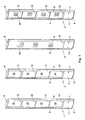
- Fig. 1 schematically shows by way of example four multifunctional antenna frames 1, 2, 3, and 4 according to the invention.
- the antenna frames are arranged for modular construction and can receive various modules, depending on the end user's wishes.
- the antenna frames take the form of a column, built up from two uprights 5, 6, which, as desired, may be profiled in the longitudinal direction, by means of a profiled continuous cross section. At the bottom, the uprights are connected by a base section 7 and at the top the uprights are connected by a top plate 8, serving as upper bridge.
- the base section 7 may be provided with a lower baseplate 9, serving as pedestal, a top part or upper baseplate 10, and two cover plates 11 serving as wall elements, one of which can be seen.
- the cover plates 11 are preferably simple to remove and to mount, respectively, for instance by means of a snap-fit system, and enclose a hollow space, in which electronic modules, as for an article surveillance system, may be accommodated.
- the uprights 5, 6 are further connected by a number of crossbars 12. If desired, the top plate 8 and the baseplates 9 and 10 may also be arranged on such crossbars 12.
- the thus formed antenna frame has hollow parts, comprising hollow uprights and one or more hollow crossbars and/or hollow top plates and baseplates, or hollow crossbars adjacent the top plates and/or baseplates.
- the antenna frame is furthermore provided, preferably already so in standard designs, with wiring, which extends in or on the hollow parts for forming one or more antenna loops and providing supply energy and a signal connection for modules to be connected.
- the antenna frame 2 is provided with a primary customer counting module 15, working for instance with infrared radiation, which can for instance cooperate with a complementary or secondary customer counting module arranged in an antenna frame placed opposite the respective antenna frame.
- a primary customer counting module working for instance with infrared radiation
- a complementary or secondary customer counting module arranged in an antenna frame placed opposite the respective antenna frame.
- modules may be formed by a module for person identification and registration, for data storage of detected labels optionally in combination with a goods storage system.
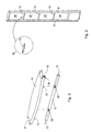
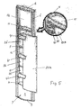
- Fig. 2 schematically shows how a module, such as customer counting module 15, may be assembled and Fig. 3 shows this customer counting module 15 on a larger scale.
- the customer counting module 15 has a shape such that the module fits precisely between the uprights 5 and 6, with the ends 16, 17 of the module partly embracing the uprights. Preferably, the ends 16, 17 fit to the uprights in a form-closing manner.
- the module 15 shown has two springing clamping brackets 18, which can engage around the bar 12.
- the bar 12, as can be seen in Fig. 3 has one or more openings or recesses, in which one or more contacts 20 are situated, which are connected with wiring 21, 22.
- the module 15 is provided with corresponding contact elements 23, of which one is shown in Fig. 3 .
- the antenna frame 3 in Fig. 1 is provided on opposite sides with cover plates 25, which in this example extend from the base section 7 up to the top plate 8. It is also possible that the cover plates extend only over a part of the height of an antenna frame and leave clear one or more open compartments 26 situated between the bars 12. It is also possible to arrange the cover plate 25, if desired, on one side of the antenna frame only.
- the cover plates can be simply mounted and removed, for instance using a snap-fit system.
- the cover plates may be provided with scenes and/or colors desired by the user.
- the cover plates may also be provided with commercial information and/or notices for the visitors. For instance, on the cover plates, for instance particular articles from the store supply or from third parties may be advertised, or services offered by the shop organization or others.
- the antenna frame indicated with reference numeral 4 is provided with a cover plate 25 on one side only.
- a cover plate situated on the side of an antenna frame remote from the passageway between two antenna frames may also serve as a shielding plate to bound the detection field.
- Fig. 4 schematically shows a base section of an example of an antenna column according to the invention.
- the figure illustrates that a communication and control unit 30 can be placed in the base of an antenna column.
- the unit can preferably be mounted according to the "plug & play" system and may for instance be suitable for the EASi information exchange system for anti-shoplifting systems, marketed by applicant, whereby a number of the antennas are connected to a network, so that the information obtained from the antennas can be centrally collected, processed and managed.
- Such a unit can contain a modem and can for instance count the number of alarm signals, count the number of customers and the number of times that a label is deactivated at a cash desk.
- the unit can comprise an analog modem, or may be suitable for a LAN (local area network) connection, wired or wireless, or may be provided with a GSM/GPRS modem.
- Fig. 4 at 31 further shows connecting means for the electronics to be inserted.
- the user may, if desired, start with antenna frames that are designed only as carriers for, for instance, advertising expressions ("poster holder"), as indicated in Fig. 1 at 4 .
- customer counting modules may be added. Since assembly is simple, this can be done by the user himself. Also, a matching unit with customer electronics then needs to be added. This can then be mounted in the base section. In principle, it is also possible to accommodate this electronics unit in the customer counting module.
- the user can add the anti-shoplifting function by mounting a suitable unit for electronic article surveillance, also EAS electronics unit, in the base of the antenna frame. Any customer electronics already present may then be canceled since the EAS electronics then fulfills this function.
- a suitable unit for electronic article surveillance also EAS electronics unit
- the anti-shoplifting function may thereafter be expanded, if desired, to include a network function and remote control and maintenance.
- the EASi module already mentioned may be added.
- the antenna frames are in principle connected to the usual supply voltage, but in principle it is possible for the various units or modules to be designed for battery supply.
- the antenna frames 3 and 4 in Fig. 1 are provided with a cover plate 25 at least on one side.
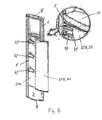
- the cover plate is of multilayer design in an embodiment according to Figs. 5-9 .
- Fig. 5 it is shown how first a back plate 25A, following arrows 41, is inserted into a longitudinal groove of the profiled upright 5.
- arrows 43 it is indicated by means of arrows 43 how a vertical longitudinal edge on the left-hand side of the back plate 25A is slid into the longitudinal groove of the upright 5.
- the back plate 25A is then caused to bulge under its own resilience and inserted, by a right-hand side thereof, into an opposite groove in the other upright 6. Once inserted into both grooves, the back plate 25A will be held in place in slightly bulged condition under the influence of its own elastic tension.
- a cover plate 25B following the arrows 45, is placed on a poster 33. Care is taken here, as can be seen in Fig. 7 , that the edges and corners of the cover plate 25B and the poster 33 coincide.
- Figs. 6 and 7 show that the cover plate 25B is provided with beveled or cut-off, or possibly rounded, corner points 35, 37 situated at the top and bottom corner points of the right-hand vertical longitudinal side. Also, in the top and bottom edge, notches 51, 53 are provided. The beveled corner points 35, 37 (see also inset in Fig. 7 ) simplify the insertion of the cover plate 25B into the respective longitudinal groove of the profiled upright. The notches 51, 53 simplify removing the cover plate 25B for replacing the poster 33.
- FIG. 9 further shows how, from the right-hand top corner, the rest of the cover plate 25B can be pressed into the groove by movement of the hand from the top down (arrow 55).
- the back plate 25A, the poster 33 and the cover plate 25B are translucent. In this way, with lighting arranged within the frame openings 26 (see Fig. 5 ), particular attention may be drawn to the advertising messages that may be present on the poster 33. It is then of further advantage if the cover plate 25A is moreover transparent.
- the bulged shape of the multilayer display plate 25A, 25B may further be supported by a corresponding shape of the module 15, or possibly by a correspondingly shaped crossbar 12 and/or the base top part 10.
Landscapes
- Engineering & Computer Science (AREA)
- Physics & Mathematics (AREA)
- Signal Processing (AREA)
- Automation & Control Theory (AREA)
- Computer Security & Cryptography (AREA)
- Electromagnetism (AREA)
- General Physics & Mathematics (AREA)
- Burglar Alarm Systems (AREA)
- Support Of Aerials (AREA)
Applications Claiming Priority (1)
| Application Number | Priority Date | Filing Date | Title |
|---|---|---|---|
| NL1033629A NL1033629C2 (nl) | 2007-04-02 | 2007-04-02 | Modulair multifunctioneel antenneframe voor een anti-winkeldiefstalsysteem. |
Publications (2)
| Publication Number | Publication Date |
|---|---|
| EP1978593A1 true EP1978593A1 (de) | 2008-10-08 |
| EP1978593B1 EP1978593B1 (de) | 2010-12-29 |
Family
ID=38543974
Family Applications (1)
| Application Number | Title | Priority Date | Filing Date |
|---|---|---|---|
| EP08153799A Not-in-force EP1978593B1 (de) | 2007-04-02 | 2008-03-31 | Modularer multifunktionaler Antennenrahmen für ein anti-Ladendiebstahlsystem |
Country Status (4)
| Country | Link |
|---|---|
| EP (1) | EP1978593B1 (de) |
| AT (1) | ATE493773T1 (de) |
| DE (1) | DE602008004182D1 (de) |
| NL (1) | NL1033629C2 (de) |
Cited By (1)
| Publication number | Priority date | Publication date | Assignee | Title |
|---|---|---|---|---|
| EP4047575A1 (de) * | 2021-02-15 | 2022-08-24 | Distribución y Marketing Ltda. | Sockelalarm |
Citations (3)
| Publication number | Priority date | Publication date | Assignee | Title |
|---|---|---|---|---|
| EP0668626A1 (de) | 1994-02-18 | 1995-08-23 | Sensormatic Electronics Corporation | Antennentragekonstruktion |
| EP0703637A1 (de) * | 1994-09-23 | 1996-03-27 | Actron Entwicklungs AG | Antenne für ein elektronisches Sicherungssystem |
| FR2809279A1 (fr) * | 2000-05-18 | 2001-11-23 | Lionel Prat | Habillage pour une antenne d'appareil de detection d'objets, et appareil de detection comportant une antenne equipee d'un tel habillage |
-
2007
- 2007-04-02 NL NL1033629A patent/NL1033629C2/nl active Search and Examination
-
2008
- 2008-03-31 EP EP08153799A patent/EP1978593B1/de not_active Not-in-force
- 2008-03-31 DE DE602008004182T patent/DE602008004182D1/de active Active
- 2008-03-31 AT AT08153799T patent/ATE493773T1/de not_active IP Right Cessation
Patent Citations (3)
| Publication number | Priority date | Publication date | Assignee | Title |
|---|---|---|---|---|
| EP0668626A1 (de) | 1994-02-18 | 1995-08-23 | Sensormatic Electronics Corporation | Antennentragekonstruktion |
| EP0703637A1 (de) * | 1994-09-23 | 1996-03-27 | Actron Entwicklungs AG | Antenne für ein elektronisches Sicherungssystem |
| FR2809279A1 (fr) * | 2000-05-18 | 2001-11-23 | Lionel Prat | Habillage pour une antenne d'appareil de detection d'objets, et appareil de detection comportant une antenne equipee d'un tel habillage |
Cited By (1)
| Publication number | Priority date | Publication date | Assignee | Title |
|---|---|---|---|---|
| EP4047575A1 (de) * | 2021-02-15 | 2022-08-24 | Distribución y Marketing Ltda. | Sockelalarm |
Also Published As
| Publication number | Publication date |
|---|---|
| EP1978593B1 (de) | 2010-12-29 |
| DE602008004182D1 (de) | 2011-02-10 |
| ATE493773T1 (de) | 2011-01-15 |
| NL1033629C2 (nl) | 2008-10-06 |
Similar Documents
| Publication | Publication Date | Title |
|---|---|---|
| US4773175A (en) | Display board for a shopping cart | |
| CA2441221C (en) | Conversion tower display system | |
| EP0689180A1 (de) | Schutzhülle für ein elektronisches Etikett | |
| US5901482A (en) | Display card holder for a shopping cart | |
| US20110192812A1 (en) | Product merchandising outpost system | |
| US9615677B2 (en) | Retail fixture with slot | |
| EP2078480A1 (de) | Klappauslagemodul | |
| US20100013662A1 (en) | Product locating system | |
| US7367149B2 (en) | Label holder | |
| US20170103686A1 (en) | Modular flush-mount sign channel track system and method | |
| CN108334298A (zh) | 一种电子标签智能显示系统及方法 | |
| WO2006029288A3 (en) | Modular shipping unit and system | |
| EP1978593B1 (de) | Modularer multifunktionaler Antennenrahmen für ein anti-Ladendiebstahlsystem | |
| AU4052600A (en) | Electronic tags incorporating a customer attracting annunciator for use in electronic product information display systems | |
| WO2005077133A3 (en) | Self-contained merchandise display and service system | |
| JP2001299523A (ja) | 化粧品陳列台 | |
| WO2020086368A1 (en) | System and method for product display | |
| US11564508B2 (en) | Phone case wall display and organizer | |
| WO2014174156A1 (en) | Quick attach information element to be connected on a graphic surface | |
| CN102149304B (zh) | 广告展示系统 | |
| US6783066B2 (en) | On-premises paging system utilizing mounted pagers having a data input device | |
| US5367800A (en) | Interchangeable display system | |
| ES2515744T3 (es) | Un sistema que comprende un módulo de torre, un módulo superior así como una pluralidad de módulos adicionales | |
| BE1029895B1 (nl) | Uitstalkast en bouwpakket daarvoor | |
| CN216569251U (zh) | 多层茶饮料架 |
Legal Events
| Date | Code | Title | Description |
|---|---|---|---|
| PUAI | Public reference made under article 153(3) epc to a published international application that has entered the european phase |
Free format text: ORIGINAL CODE: 0009012 |
|
| AK | Designated contracting states |
Kind code of ref document: A1 Designated state(s): AT BE BG CH CY CZ DE DK EE ES FI FR GB GR HR HU IE IS IT LI LT LU LV MC MT NL NO PL PT RO SE SI SK TR |
|
| AX | Request for extension of the european patent |
Extension state: AL BA MK RS |
|
| 17P | Request for examination filed |
Effective date: 20090313 |
|
| 17Q | First examination report despatched |
Effective date: 20090414 |
|
| AKX | Designation fees paid |
Designated state(s): AT BE BG CH CY CZ DE DK EE ES FI FR GB GR HR HU IE IS IT LI LT LU LV MC MT NL NO PL PT RO SE SI SK TR |
|
| GRAP | Despatch of communication of intention to grant a patent |
Free format text: ORIGINAL CODE: EPIDOSNIGR1 |
|
| GRAS | Grant fee paid |
Free format text: ORIGINAL CODE: EPIDOSNIGR3 |
|
| GRAA | (expected) grant |
Free format text: ORIGINAL CODE: 0009210 |
|
| AK | Designated contracting states |
Kind code of ref document: B1 Designated state(s): AT BE BG CH CY CZ DE DK EE ES FI FR GB GR HR HU IE IS IT LI LT LU LV MC MT NL NO PL PT RO SE SI SK TR |
|
| REG | Reference to a national code |
Ref country code: GB Ref legal event code: FG4D |
|
| REG | Reference to a national code |
Ref country code: CH Ref legal event code: EP |
|
| REG | Reference to a national code |
Ref country code: IE Ref legal event code: FG4D |
|
| REF | Corresponds to: |
Ref document number: 602008004182 Country of ref document: DE Date of ref document: 20110210 Kind code of ref document: P |
|
| REG | Reference to a national code |
Ref country code: DE Ref legal event code: R096 Ref document number: 602008004182 Country of ref document: DE Effective date: 20110210 |
|
| REG | Reference to a national code |
Ref country code: NL Ref legal event code: VDEP Effective date: 20101229 |
|
| PG25 | Lapsed in a contracting state [announced via postgrant information from national office to epo] |
Ref country code: LT Free format text: LAPSE BECAUSE OF FAILURE TO SUBMIT A TRANSLATION OF THE DESCRIPTION OR TO PAY THE FEE WITHIN THE PRESCRIBED TIME-LIMIT Effective date: 20101229 |
|
| LTIE | Lt: invalidation of european patent or patent extension |
Effective date: 20101229 |
|
| PG25 | Lapsed in a contracting state [announced via postgrant information from national office to epo] |
Ref country code: AT Free format text: LAPSE BECAUSE OF FAILURE TO SUBMIT A TRANSLATION OF THE DESCRIPTION OR TO PAY THE FEE WITHIN THE PRESCRIBED TIME-LIMIT Effective date: 20101229 Ref country code: LV Free format text: LAPSE BECAUSE OF FAILURE TO SUBMIT A TRANSLATION OF THE DESCRIPTION OR TO PAY THE FEE WITHIN THE PRESCRIBED TIME-LIMIT Effective date: 20101229 Ref country code: BG Free format text: LAPSE BECAUSE OF FAILURE TO SUBMIT A TRANSLATION OF THE DESCRIPTION OR TO PAY THE FEE WITHIN THE PRESCRIBED TIME-LIMIT Effective date: 20110329 Ref country code: FI Free format text: LAPSE BECAUSE OF FAILURE TO SUBMIT A TRANSLATION OF THE DESCRIPTION OR TO PAY THE FEE WITHIN THE PRESCRIBED TIME-LIMIT Effective date: 20101229 Ref country code: SE Free format text: LAPSE BECAUSE OF FAILURE TO SUBMIT A TRANSLATION OF THE DESCRIPTION OR TO PAY THE FEE WITHIN THE PRESCRIBED TIME-LIMIT Effective date: 20101229 Ref country code: CY Free format text: LAPSE BECAUSE OF FAILURE TO SUBMIT A TRANSLATION OF THE DESCRIPTION OR TO PAY THE FEE WITHIN THE PRESCRIBED TIME-LIMIT Effective date: 20101229 Ref country code: SI Free format text: LAPSE BECAUSE OF FAILURE TO SUBMIT A TRANSLATION OF THE DESCRIPTION OR TO PAY THE FEE WITHIN THE PRESCRIBED TIME-LIMIT Effective date: 20101229 Ref country code: HR Free format text: LAPSE BECAUSE OF FAILURE TO SUBMIT A TRANSLATION OF THE DESCRIPTION OR TO PAY THE FEE WITHIN THE PRESCRIBED TIME-LIMIT Effective date: 20101229 |
|
| PG25 | Lapsed in a contracting state [announced via postgrant information from national office to epo] |
Ref country code: ES Free format text: LAPSE BECAUSE OF FAILURE TO SUBMIT A TRANSLATION OF THE DESCRIPTION OR TO PAY THE FEE WITHIN THE PRESCRIBED TIME-LIMIT Effective date: 20110409 Ref country code: GR Free format text: LAPSE BECAUSE OF FAILURE TO SUBMIT A TRANSLATION OF THE DESCRIPTION OR TO PAY THE FEE WITHIN THE PRESCRIBED TIME-LIMIT Effective date: 20110330 Ref country code: BE Free format text: LAPSE BECAUSE OF FAILURE TO SUBMIT A TRANSLATION OF THE DESCRIPTION OR TO PAY THE FEE WITHIN THE PRESCRIBED TIME-LIMIT Effective date: 20101229 Ref country code: CZ Free format text: LAPSE BECAUSE OF FAILURE TO SUBMIT A TRANSLATION OF THE DESCRIPTION OR TO PAY THE FEE WITHIN THE PRESCRIBED TIME-LIMIT Effective date: 20101229 Ref country code: IS Free format text: LAPSE BECAUSE OF FAILURE TO SUBMIT A TRANSLATION OF THE DESCRIPTION OR TO PAY THE FEE WITHIN THE PRESCRIBED TIME-LIMIT Effective date: 20110429 Ref country code: PT Free format text: LAPSE BECAUSE OF FAILURE TO SUBMIT A TRANSLATION OF THE DESCRIPTION OR TO PAY THE FEE WITHIN THE PRESCRIBED TIME-LIMIT Effective date: 20110429 Ref country code: NO Free format text: LAPSE BECAUSE OF FAILURE TO SUBMIT A TRANSLATION OF THE DESCRIPTION OR TO PAY THE FEE WITHIN THE PRESCRIBED TIME-LIMIT Effective date: 20110329 Ref country code: EE Free format text: LAPSE BECAUSE OF FAILURE TO SUBMIT A TRANSLATION OF THE DESCRIPTION OR TO PAY THE FEE WITHIN THE PRESCRIBED TIME-LIMIT Effective date: 20101229 |
|
| PG25 | Lapsed in a contracting state [announced via postgrant information from national office to epo] |
Ref country code: NL Free format text: LAPSE BECAUSE OF FAILURE TO SUBMIT A TRANSLATION OF THE DESCRIPTION OR TO PAY THE FEE WITHIN THE PRESCRIBED TIME-LIMIT Effective date: 20101229 Ref country code: SK Free format text: LAPSE BECAUSE OF FAILURE TO SUBMIT A TRANSLATION OF THE DESCRIPTION OR TO PAY THE FEE WITHIN THE PRESCRIBED TIME-LIMIT Effective date: 20101229 Ref country code: RO Free format text: LAPSE BECAUSE OF FAILURE TO SUBMIT A TRANSLATION OF THE DESCRIPTION OR TO PAY THE FEE WITHIN THE PRESCRIBED TIME-LIMIT Effective date: 20101229 Ref country code: PL Free format text: LAPSE BECAUSE OF FAILURE TO SUBMIT A TRANSLATION OF THE DESCRIPTION OR TO PAY THE FEE WITHIN THE PRESCRIBED TIME-LIMIT Effective date: 20101229 |
|
| PG25 | Lapsed in a contracting state [announced via postgrant information from national office to epo] |
Ref country code: MC Free format text: LAPSE BECAUSE OF NON-PAYMENT OF DUE FEES Effective date: 20110331 Ref country code: DK Free format text: LAPSE BECAUSE OF FAILURE TO SUBMIT A TRANSLATION OF THE DESCRIPTION OR TO PAY THE FEE WITHIN THE PRESCRIBED TIME-LIMIT Effective date: 20101229 |
|
| PLBE | No opposition filed within time limit |
Free format text: ORIGINAL CODE: 0009261 |
|
| STAA | Information on the status of an ep patent application or granted ep patent |
Free format text: STATUS: NO OPPOSITION FILED WITHIN TIME LIMIT |
|
| 26N | No opposition filed |
Effective date: 20110930 |
|
| REG | Reference to a national code |
Ref country code: FR Ref legal event code: ST Effective date: 20111130 |
|
| PG25 | Lapsed in a contracting state [announced via postgrant information from national office to epo] |
Ref country code: MT Free format text: LAPSE BECAUSE OF FAILURE TO SUBMIT A TRANSLATION OF THE DESCRIPTION OR TO PAY THE FEE WITHIN THE PRESCRIBED TIME-LIMIT Effective date: 20101229 |
|
| REG | Reference to a national code |
Ref country code: IE Ref legal event code: MM4A |
|
| REG | Reference to a national code |
Ref country code: DE Ref legal event code: R097 Ref document number: 602008004182 Country of ref document: DE Effective date: 20110930 |
|
| PG25 | Lapsed in a contracting state [announced via postgrant information from national office to epo] |
Ref country code: DE Free format text: LAPSE BECAUSE OF NON-PAYMENT OF DUE FEES Effective date: 20111001 Ref country code: FR Free format text: LAPSE BECAUSE OF NON-PAYMENT OF DUE FEES Effective date: 20110331 Ref country code: IE Free format text: LAPSE BECAUSE OF NON-PAYMENT OF DUE FEES Effective date: 20110331 |
|
| REG | Reference to a national code |
Ref country code: DE Ref legal event code: R119 Ref document number: 602008004182 Country of ref document: DE Effective date: 20111001 |
|
| PG25 | Lapsed in a contracting state [announced via postgrant information from national office to epo] |
Ref country code: IT Free format text: LAPSE BECAUSE OF FAILURE TO SUBMIT A TRANSLATION OF THE DESCRIPTION OR TO PAY THE FEE WITHIN THE PRESCRIBED TIME-LIMIT Effective date: 20101229 |
|
| REG | Reference to a national code |
Ref country code: CH Ref legal event code: PL |
|
| GBPC | Gb: european patent ceased through non-payment of renewal fee |
Effective date: 20120331 |
|
| PG25 | Lapsed in a contracting state [announced via postgrant information from national office to epo] |
Ref country code: CH Free format text: LAPSE BECAUSE OF NON-PAYMENT OF DUE FEES Effective date: 20120331 Ref country code: GB Free format text: LAPSE BECAUSE OF NON-PAYMENT OF DUE FEES Effective date: 20120331 Ref country code: LI Free format text: LAPSE BECAUSE OF NON-PAYMENT OF DUE FEES Effective date: 20120331 |
|
| PG25 | Lapsed in a contracting state [announced via postgrant information from national office to epo] |
Ref country code: LU Free format text: LAPSE BECAUSE OF NON-PAYMENT OF DUE FEES Effective date: 20110331 |
|
| PG25 | Lapsed in a contracting state [announced via postgrant information from national office to epo] |
Ref country code: TR Free format text: LAPSE BECAUSE OF FAILURE TO SUBMIT A TRANSLATION OF THE DESCRIPTION OR TO PAY THE FEE WITHIN THE PRESCRIBED TIME-LIMIT Effective date: 20101229 |
|
| PG25 | Lapsed in a contracting state [announced via postgrant information from national office to epo] |
Ref country code: HU Free format text: LAPSE BECAUSE OF FAILURE TO SUBMIT A TRANSLATION OF THE DESCRIPTION OR TO PAY THE FEE WITHIN THE PRESCRIBED TIME-LIMIT Effective date: 20101229 |