EP1978732B1 - Abbildungsvorrichtung - Google Patents
Abbildungsvorrichtung Download PDFInfo
- Publication number
- EP1978732B1 EP1978732B1 EP08251248A EP08251248A EP1978732B1 EP 1978732 B1 EP1978732 B1 EP 1978732B1 EP 08251248 A EP08251248 A EP 08251248A EP 08251248 A EP08251248 A EP 08251248A EP 1978732 B1 EP1978732 B1 EP 1978732B1
- Authority
- EP
- European Patent Office
- Prior art keywords
- section
- photometry
- luminosity
- exposure
- dark region
- Prior art date
- Legal status (The legal status is an assumption and is not a legal conclusion. Google has not performed a legal analysis and makes no representation as to the accuracy of the status listed.)
- Ceased
Links
- 238000003384 imaging method Methods 0.000 title claims description 33
- 230000006872 improvement Effects 0.000 claims description 33
- 238000005375 photometry Methods 0.000 claims description 25
- 238000003702 image correction Methods 0.000 claims description 17
- 238000012937 correction Methods 0.000 claims description 14
- 238000009499 grossing Methods 0.000 claims description 5
- 238000006243 chemical reaction Methods 0.000 description 7
- 238000010586 diagram Methods 0.000 description 5
- 230000035945 sensitivity Effects 0.000 description 5
- 238000005516 engineering process Methods 0.000 description 4
- 230000008859 change Effects 0.000 description 3
- 230000007246 mechanism Effects 0.000 description 2
- 238000012986 modification Methods 0.000 description 2
- 230000004048 modification Effects 0.000 description 2
- 238000013459 approach Methods 0.000 description 1
- 238000010276 construction Methods 0.000 description 1
- 230000000694 effects Effects 0.000 description 1
- 230000002708 enhancing effect Effects 0.000 description 1
- 239000013589 supplement Substances 0.000 description 1
- 230000000153 supplemental effect Effects 0.000 description 1
Images



Classifications
-
- H—ELECTRICITY
- H04—ELECTRIC COMMUNICATION TECHNIQUE
- H04N—PICTORIAL COMMUNICATION, e.g. TELEVISION
- H04N23/00—Cameras or camera modules comprising electronic image sensors; Control thereof
- H04N23/70—Circuitry for compensating brightness variation in the scene
-
- H—ELECTRICITY
- H04—ELECTRIC COMMUNICATION TECHNIQUE
- H04N—PICTORIAL COMMUNICATION, e.g. TELEVISION
- H04N23/00—Cameras or camera modules comprising electronic image sensors; Control thereof
- H04N23/70—Circuitry for compensating brightness variation in the scene
- H04N23/71—Circuitry for evaluating the brightness variation
-
- H—ELECTRICITY
- H04—ELECTRIC COMMUNICATION TECHNIQUE
- H04N—PICTORIAL COMMUNICATION, e.g. TELEVISION
- H04N23/00—Cameras or camera modules comprising electronic image sensors; Control thereof
- H04N23/70—Circuitry for compensating brightness variation in the scene
- H04N23/76—Circuitry for compensating brightness variation in the scene by influencing the image signals
-
- H—ELECTRICITY
- H04—ELECTRIC COMMUNICATION TECHNIQUE
- H04N—PICTORIAL COMMUNICATION, e.g. TELEVISION
- H04N2101/00—Still video cameras
Definitions
- the present embodiments relate to an imaging apparatus.
- US Patent application US 2002/0036697 relates to a digital camera which can change gradation properties.
- the camera comprises a CCD image pickup element for photographing a subject, an exposure control mechanism for controlling an exposure on the image pickup element, a digital processing circuit including a gradation converting circuit for being capable of generating image signals having different gradation properties (gamma properties) based on the output signal from the image pickup element, and a system controller including a selecting circuit for selecting one of the different gradation properties, which is used in the gradation converting circuit.
- the exposure control mechanism changes a control target value to control the exposure in accordance with the selected gamma value so that the output level is maintained at constant in the average exposure.
- the present embodiments provide a technology adaptively enhancing appearance of image data in addition to image correction that makes the dark region bright.
- Fig. 1 illustrates a configuration of an imaging apparatus 11.
- an imaging apparatus 11 is mounted with a shooting lens 12.
- the shooting lens 12 is provided with an aperture 12a.
- a shutter 13a and an image sensor 13 are arranged in an image space of this shooting lens 12.
- An operation of this image sensor 13 is controlled by an output pulse of a timing generator 22b.
- Image data generated by the image sensor 13 is stored temporarily in a buffer memory 17 via a signal processing section 15 (including a gain adjusting section corresponding to an imaging sensitivity) and an A/D converting section 16.
- the buffer memory 17 is coupled with a bus 18.
- An image processing section 19, a card interface 20, a microprocessor 22, a compressing/decompressing section 23, and an image display section 24 are coupled with the bus 18.
- the card interface 20 records the image data into a detachable memory card 21.
- a switch group 22a of the imaging apparatus 11, the timing generator 22b, and a photometric sensor 22c are coupled with the microprocessor 22.
- the microprocessor 22 performs control of the aperture 12a and the shutter 13a, too.
- the image display section 24 displays images and the like on a monitor screen 25 provided on a back of the imaging apparatus 11.
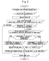
- Fig. 2 illustrates an operation of the imaging apparatus 11. There will be described this operation along a step number illustrated in Fig. 2 below.
- Step 1 The microprocessor 22 performs the photometry and the exposure calculation, and determines the exposure conditions (an aperture value, a charge accumulating time, an imaging sensitivity, or the like) of the subject. This operation will be described in detail later.
- Step 2 The microprocessor 22 detects depression of a shutter release by a user via the switch group 22a.
- the microprocessor 22 returns the operation to Step 1.
- Step 3 The microprocessor 22 drives the aperture 12a, the shutter 13a, the timing generator 22b or the like, and images the subject in accordance with the exposure conditions (aperture value, and charge accumulating time) set on Step 1.
- the signal processing section 15 amplifies image data by applying an imaging gain to meet the imaging sensitivity to the image data read from the image sensor 13.
- the amplified image data is A/D converted with an A/D converting section 16 and then recorded temporarily in the buffer memory 17.
- Step 4 The image processing section 19 performs a usual image processing such as a tone conversion (gamma conversion) or a color space conversion on the image data within the buffer memory 17.
- a tone conversion gamma conversion
- a color space conversion on the image data within the buffer memory 17.
- Step 5 The user can preliminarily set a reservation of an image correction to be performed on the image data by operating the switch group 22a.
- As one of the image corrections like D-Lighting, there is prepared the image correction to perform the improvement of luminosity in the dark region.
- the microprocessor 22 determines whether or not to perform the improvement of luminosity in the dark region while referring to a correction setting data of the image correction.
- the microprocessor 22 shifts the operation to Step 12.
- the microprocessor 22 shifts the operation to Step 6.
- Step 6 The image processing section 19 performs smoothing processing according to below formula on a luminance component Y (x, y) of the image data to obtain a smoothed image YL (x, y).
- (x, y) is coordinate values representing the position of a pixel to be processed.
- (i, j) is relative coordinate value of neighboring pixels reflecting on the smoothing processing.
- r is a radius value indicating selection range of the neighboring pixel.
- Lpw is a weighted ratio of the neighboring pixel as illustrated in Fig. 3 . It is possible to know whether a pixel position (x, y) of the image data is located within bright region or dark region, from pixel values of the smoothed image YL (x, y) thus obtained.
- Step 7 The microprocessor 22 determines in which of stronger mode or weaker mode the improvement of luminosity in the dark region is performed while referring to correction setting data of the image correction.
- the microprocessor 22 shifts the operation to Step 8.
- the microprocessor 22 shifts the operation to Step 9.
- Step 8 The microprocessor 22 selects a weaker parameter fg from two kinds of parameters fg as illustrated in Fig. 4 , and sets it to the image processing section 19.
- this parameter fg is reduced monotonously, and approaches 1 as a neighbor region including the pixel position (x, y) of the image data becomes brighter (as a value of the smoothed image YL (x, y) becomes larger). Conversely, the value of the parameter fg becomes larger, as the neighbor region becomes darker (the value of the smoothed image YL (x, y) becomes smaller).
- Step 10 After setting this parameter fg, the microprocessor 22 shifts the operation to Step 10.
- Step 9 The microprocessor 22 selects the stronger parameter fg from two kinds of parameters fg as illustrated in Fig. 4 , and sets it to the image processing section 19.
- the stronger parameter fg has larger value than the weaker parameter fg set in Step 8.
- Step 10 After setting the stronger parameter fg, the microprocessor 22 shifts the operation to Step 10.
- Step 10 The Image processing section 19 substitutes a value of the smoothed image YL (x, y) obtained in Step 6 to the set parameter fg, and obtains a gain map GM (x, y).
- GM x y fg YL x y
- Step 11 The image processing section 19 performs a tone correction due to the gain map GM (x, y) as below formulas on signal components RGB of the image data within the buffer memory 17, and obtains the image data Rc, Gc, Bc after tone correction.
- Rc x y R x y ⁇ GM x ⁇ y
- Gc x y G x y ⁇ GM x ⁇ y
- Bc x y B x y ⁇ GM x ⁇ y
- the dark region of the image data is corrected brightly.
- Step 12 The card interface 20 compresses and preserves the image data into the memory card 21.
- Fig. 5 illustrates operations (photometry and exposure calculation) of Step 1 described above.
- Step 31 The microprocessor 22 obtains the correction setting data with respect to the image correction (above described Steps 5 to 11) reserved and set to the image data after the imaging.
- Step 32 A photometry sensor 22c divides the subject into five regions illustrated in Fig. 6 to perform photometry.
- the microprocessor 22 obtains five values of divisional photometry Bv[1] to Bv[5] as a result of the divisional photometry.
- division of photometry it is not limited to five divisions illustrated in Fig. 6 . Practically, the division of photometry may be determined according to the specifications of a photometric sensor 22c.
- Step 33 The microprocessor 22 substitutes the values of divisional photometry Bv[1] to Bv [5] into below formulas, and obtains an average photometric value Bv MEAN , a photometric value of bright area Bv MAX , and a photometric value of central area Bvc.
- Bv MEAN Bv 1 + Bv 2 + Bv 3 + Bv 4 + Bv 5 / 5
- Step 34 The microprocessor 22 calculates an exposure control value Bv CNTL while substituting a value obtained with Step 33 into a formula [4].
- Bv CNTL k ⁇ 1 ⁇ Bv MEAN + k ⁇ 2 ⁇ Bv MAX + k ⁇ 3 ⁇ Bvc + k ⁇ 4 where, the reflecting proportions k1 to k3 and the value of an offset value k4 within the formula [4] are determined so as to follow rules below described.
- Fig. 7 illustrates one example of the setting table of values k1 to k4 following these rules.
- values k1 to k4 may be adjusted along the rules (1) to (5) so that the tone reproduction of the image data after the image correction becomes preferable in various photographing scene.
- Step 35 The microprocessor 22 performs the known exposure calculation based on the exposure control value Bv CNTL calculated in Step 34 to determine the exposure conditions (the aperture value, the charge accumulating time, the imaging sensitivity, or the like). After the operation described above, the microprocessor 22 ends routines of the photometry and the exposure calculation, and returns the operation to Step 2 of a main routine ( Fig. 2 ). (Effects of the Present Embodiments)
- the exposure condition at the time of the photographing is adaptively changed.
- it becomes possible to obtain the image data with preferable tone reproducibility by balancing the tone reproduction in the dark region due to the improvement of luminosity and the tone reproduction in the bright region due to the exposure conditions.
- the offset value k4 of the exposure control value Bv CNTL is reduced.
- the exposure control value Bv CNTL itself is lowered, and the exposure conditions at the time of photographing are complementarily increased.
- the image data are wholly imaged brightly; and thus it is possible to supplement insufficient tone of the dark region.
- the offset value k4 of the exposure control value Bv CNTL becomes large.
- the exposure control value Bv CNTL itself increases, and the exposure conditions at the time of imaging complementarily become low. As a result, it is possible to improve insufficient tone (blown out or the like) of the bright region due to lower exposure conditions while performing the improvement of luminosity in the dark region by the image correction.
- the reflecting proportion k2 of the photometric value of bright area Bv MAX is made small.
- the exposure conditions are determined, while relatively emphasizing the dark region.
- the dark region of the image data is imaged brightly, and thus insufficient tone of the dark region can be supplemented.
- the reflecting proportion k2 of the photometric value of bright area Bv MAX becomes large.
- the exposure conditions are determined while emphasizing the bright region.
- the insufficient tone (blown out or the like) of the bright region can be improved with the exposure conditions of emphasizing the bright region while performing the improvement of luminosity in the dark region by the image correction.
- the exposure conditions are made low by changing the offset value k4.
- the stronger the improvement of luminosity in the dark region is performed, the lower the exposure conditions become, and accordingly, it is possible to further improve the insufficient tone (blown out or the like) of the bright region.
- the reflecting proportion k2 of the photometric value of bright area Bv MAX is made large.
- the exposure conditions are determined while further emphasizing the bright region.
- the stronger the improvement of luminosity in the dark region is made, the more it becomes the exposure conditions of emphasizing the bright region, and accordingly it is possible to further improve the insufficient tone (blown out or the like) of the bright region.
- the value of the exposure control value BV CNTL is changed.
- a setting value of an exposure correction may be changed according to a correction setting relating to the improvement of luminosity in the dark region.
- the photometric value of bright area the maximum value of divisional photometry is used.
- an average value of several upper parts of the value of divisional photometry may be used.
Landscapes
- Engineering & Computer Science (AREA)
- Multimedia (AREA)
- Signal Processing (AREA)
- Studio Devices (AREA)
- Exposure Control For Cameras (AREA)
- Facsimile Image Signal Circuits (AREA)
Claims (6)
- Abbildungsvorrichtung (11), umfassend:einen Fotometrieabschnitt (22, 22c), der eine fotometrische Messung eines Objektes ausführt;einen Belichtungsberechnungsabschnitt (22), der die Belichtungsbedingungen auf der Basis von Ergebnissen der Fotometrie des Fotometrieabschnitts (22, 22c) einstellt;einen Abbildungsabschnitt, der das Objekt gemäß den Belichtungsbedingungen abbildet, um Bilddaten zu erzeugen; undeinen Glättungsverarbeitungsabschnitt, der eine Glättungsverarbeitung an den Bilddaten ausführt, die im Abbildungsabschnitt erzeugt sind, und ein geglättetes Bild erzeugt, gekennzeichnet durcheinen Zunahmeabbildungserzeugungsabschnitt, der eine Zunahmeabbildung gemäß einer Leuchtdichtekomponente des geglätteten Bildes erzeugt, welches vom Glättungsverarbeitungsabschnitt erzeugt ist, wobei die Zunahmeabbildung von einem Zunahmebetrag abgeleitet ist, der für jedes Pixel bestimmt ist; undeinen Bildverarbeitungsabschnitt (19), der eine Bildkorrektur ausführt, um die Helligkeit in einem dunklen Bereich durch Multiplizieren der Zunahme in den RGB-Komponenten jedes Pixels der Bilddaten, die im Abbildungsabschnitt erzeugt sind, unter Verwendung der Zunahmeabbildung zu verbessern, die im Zunahmeabbildungserzeugungsabschnitt erzeugt ist,wobei der Belichtungsberechnungsabschnitt (22) die Belichtungsbedingungen gemäß der Korrektureinstellung der Bildkorrektur im Bildverarbeitungsabschnitt (19) bestimmt.
- Abbildungsvorrichtung (11) nach Anspruch 1, wobei der Belichtungsberechnungsabschnitt (22) die Belichtungbedingungen niedrig für die Korrektureinstellung einstellt, welche die Verbesserung der Helligkeit im dunklen Bereich im Vergleich mit der Korrektureinstellung bereitstellt, die keine Verbesserung der Helligkeit im dunklen Bereich bereitstellt.
- Abbildungsvorrichtung (11) nach Anspruch 1 oder 2, wobei
der Fotometrieabschnitt (22, 22c) das Objekt in mehrere Teile unterteilt und Teilungsfotometrie ausführt; und
der Belichtungsberechnungsabschnitt (22) die Belichtungsbedingungen durch Anheben des reflektierenden Anteils (k1, k2, k3, ...) eines fotometrischen Wertes eines hellen Teils unter der Werten der Teilungsfotometrie für die Korrektureinstellung einstellt, die für die Verbesserung der Helligkeit im dunklen Bereich sorgt, im Vergleich zur Korrektureinstellung, die für keine Verbesserung der Helligkeit im dunklen Bereich sorgt, wobei die fotometrischen Werte von Werten der teilungsfotometrischen Größen abgeleitet sind. - Abbildungsvorrichtung nach einem der Ansprüche 1 bis 3, wobei
der Belichtungsberechnungsabschnitt (22) die Belichtungsbedingungen niedrig einstellt, da die Korrektureinstellung einen größeren Betrag der Verbesserung in der Helligkeit des dunklen Bereichs aufweist. - Abbildungsvorrichtung nach einem der Ansprüche 1 bis 4, wobei der Fotometrieabschnitt (22, 22c) das Objekt in mehrere Teile aufteilt und Teilungsfotometrie ausführt; und
der Belichtungsberechnungsabschnitt die Belichtungsbedingungen durch Erhöhen des reflektierenden Anteils (k1, k2, k3, ...) eines fotometrischen Wertes eines hellen Teils unter den Werten der Teilungsfotometrie einstellt, da die Korrektureinstellung einen größeren Anteil der Verbesserung in der Helligkeit des dunklen Bereichs aufweist, wobei die fotometrischen Werte von Werten der teilungsfotometrischen Größen abgeleitet sind. - Abbildungsvorrichtung (11) nach Anspruch 3 oder 5, wobei mindestens einer der reflektierenden Anteile k1 , k2, k3, ... erhöht ist, und wobei die fotometrischen Werte von Werten der teilungsfotometrischen Größen abgeleitet sind, wie zum Beispiel ein durchschnittlicher fotometrischer Wert BVMEAN, ein fotometrischer Wert des hellen Bereichs Bvmax oder ein fotometrischer Wert des Zentralbereichs Bvc, nach der Formel:

wobei BvCNTL ein Belichtungskontrollwert ist.
Applications Claiming Priority (1)
| Application Number | Priority Date | Filing Date | Title |
|---|---|---|---|
| JP2007097527A JP2008258828A (ja) | 2007-04-03 | 2007-04-03 | 撮像装置 |
Publications (3)
| Publication Number | Publication Date |
|---|---|
| EP1978732A2 EP1978732A2 (de) | 2008-10-08 |
| EP1978732A3 EP1978732A3 (de) | 2008-12-17 |
| EP1978732B1 true EP1978732B1 (de) | 2011-05-04 |
Family
ID=39537893
Family Applications (1)
| Application Number | Title | Priority Date | Filing Date |
|---|---|---|---|
| EP08251248A Ceased EP1978732B1 (de) | 2007-04-03 | 2008-03-31 | Abbildungsvorrichtung |
Country Status (4)
| Country | Link |
|---|---|
| US (1) | US8085315B2 (de) |
| EP (1) | EP1978732B1 (de) |
| JP (1) | JP2008258828A (de) |
| DE (1) | DE602008006622D1 (de) |
Families Citing this family (5)
| Publication number | Priority date | Publication date | Assignee | Title |
|---|---|---|---|---|
| JP4868040B2 (ja) * | 2009-08-20 | 2012-02-01 | 株式会社ニコン | 画像処理装置、電子カメラ、および画像処理プログラム |
| US8665351B2 (en) | 2009-07-23 | 2014-03-04 | Nikon Corporation | Image processing device, electronic camera, and storage medium storing image processing program |
| JP2012105354A (ja) * | 2012-02-13 | 2012-05-31 | Nikon Corp | 画像処理装置、電子カメラ、および画像処理プログラム |
| SG11201506436RA (en) * | 2013-02-18 | 2015-09-29 | High Wind N V | Device and method for placing a rotor blade of a wind turbine |
| CN120956860A (zh) * | 2025-10-14 | 2025-11-14 | 西安创奕信息科技有限公司 | 一种极寒环境下的智能可视化监测方法及系统 |
Family Cites Families (24)
| Publication number | Priority date | Publication date | Assignee | Title |
|---|---|---|---|---|
| JP2979417B2 (ja) * | 1989-11-09 | 1999-11-15 | 株式会社ニコン | マルチ測光装置 |
| US5831676A (en) * | 1992-08-19 | 1998-11-03 | Canon Kabushiki Kaisha | Image pickup device using plural control parameters for exposure control |
| JPH0635027A (ja) | 1992-07-22 | 1994-02-10 | Nikon Corp | カメラの自動露出装置及びカメラの測光装置 |
| EP0613294B1 (de) * | 1993-02-24 | 1998-10-28 | Matsushita Electric Industrial Co., Ltd. | Vorrichtung zur Gradationskorrektur und Bildaufnahmegerät mit einer solchen Vorrichtung |
| JP3092397B2 (ja) * | 1993-06-22 | 2000-09-25 | 松下電器産業株式会社 | 撮像装置 |
| JPH08110564A (ja) * | 1994-10-13 | 1996-04-30 | Canon Inc | ファインダ表示装置を有する光学機器 |
| US5614948A (en) * | 1996-04-26 | 1997-03-25 | Intel Corporation | Camera having an adaptive gain control |
| US5991456A (en) | 1996-05-29 | 1999-11-23 | Science And Technology Corporation | Method of improving a digital image |
| TW420934B (en) * | 1999-04-09 | 2001-02-01 | Winbond Electronics Corp | Image signal processing method |
| US7088390B2 (en) | 2000-06-19 | 2006-08-08 | Olympus Optical Co., Ltd. | Imaging apparatus in which exposure control is performed to suppress changes in sensitivity due to changes in gradation mode |
| JP3854100B2 (ja) * | 2000-06-22 | 2006-12-06 | オリンパス株式会社 | 撮像装置 |
| JP3854101B2 (ja) | 2000-06-22 | 2006-12-06 | オリンパス株式会社 | 撮像装置 |
| US7199823B2 (en) * | 2001-06-18 | 2007-04-03 | Olympus Optical Co., Ltd. | Method and apparatus for improving live view performance of an image pickup apparatus for a microscope |
| JP4153715B2 (ja) * | 2002-04-08 | 2008-09-24 | 松下電器産業株式会社 | 映像信号処理装置及び映像信号処理方法 |
| JP4125084B2 (ja) * | 2002-10-08 | 2008-07-23 | キヤノン株式会社 | 画像撮像装置、プログラムおよび記録媒体 |
| JP2005130297A (ja) * | 2003-10-24 | 2005-05-19 | Olympus Corp | 信号処理システム、信号処理方法、信号処理プログラム |
| JP4289225B2 (ja) * | 2004-06-18 | 2009-07-01 | 株式会社ニコン | 画像処理装置および画像処理方法 |
| JP2006114005A (ja) * | 2004-09-17 | 2006-04-27 | Nikon Corp | 階調変換装置、プログラム、電子カメラ、およびその方法 |
| JP2006108759A (ja) | 2004-09-30 | 2006-04-20 | Fuji Photo Film Co Ltd | 撮像装置 |
| US7627189B2 (en) | 2004-10-20 | 2009-12-01 | Fujinon Corporation | Sharpness adjustment method and program and electronic endoscope apparatus |
| TWI265390B (en) | 2005-05-25 | 2006-11-01 | Benq Corp | Method for adjusting exposure of a digital image |
| JP4687492B2 (ja) * | 2006-02-14 | 2011-05-25 | 株式会社ニコン | カメラ、撮像方法、露出演算装置およびプログラム |
| JP4218723B2 (ja) * | 2006-10-19 | 2009-02-04 | ソニー株式会社 | 画像処理装置、撮像装置、画像処理方法およびプログラム |
| US20090273675A1 (en) * | 2008-05-05 | 2009-11-05 | Flir Systems Ab | Ir camera and method for use with ir camera |
-
2007
- 2007-04-03 JP JP2007097527A patent/JP2008258828A/ja active Pending
-
2008
- 2008-03-28 US US12/078,275 patent/US8085315B2/en not_active Expired - Fee Related
- 2008-03-31 DE DE602008006622T patent/DE602008006622D1/de active Active
- 2008-03-31 EP EP08251248A patent/EP1978732B1/de not_active Ceased
Also Published As
| Publication number | Publication date |
|---|---|
| US20090002521A1 (en) | 2009-01-01 |
| DE602008006622D1 (de) | 2011-06-16 |
| EP1978732A2 (de) | 2008-10-08 |
| JP2008258828A (ja) | 2008-10-23 |
| EP1978732A3 (de) | 2008-12-17 |
| US8085315B2 (en) | 2011-12-27 |
Similar Documents
| Publication | Publication Date | Title |
|---|---|---|
| US7876367B2 (en) | Imaging apparatus | |
| CN101013470B (zh) | 面部重要度确定装置和方法、及图像摄取装置 | |
| KR101352349B1 (ko) | 노출 제어장치 및 촬상 장치 | |
| US8334914B2 (en) | Gradation correcting apparatus, and recording medium storing a program recorded therein | |
| EP2429194A1 (de) | Bildverarbeitungsverfahren und -vorrichtung, bildverarbeitungsprogramm und medium mit darauf gespeichertem besagten programm | |
| JP4808578B2 (ja) | デジタルカメラおよびその制御方法 | |
| KR20080035981A (ko) | 화상처리장치, 촬상장치, 화상처리방법 및 컴퓨터 프로그램 | |
| EP1978732B1 (de) | Abbildungsvorrichtung | |
| JP5782311B2 (ja) | 撮像装置及びその制御方法 | |
| EP1998552B1 (de) | Bildgebungsvorrichtung und bildverarbeitungsprogramm | |
| JP2004007202A (ja) | 画像処理装置 | |
| US8570407B2 (en) | Imaging apparatus, image processing program, image processing apparatus, and image processing method | |
| JP2001054014A (ja) | 電子カメラ | |
| JP3831934B2 (ja) | カメラの自動露出装置 | |
| JP4941424B2 (ja) | 撮像装置および画像処理プログラム | |
| EP1976273B1 (de) | Bildverarbeitungsvorrichtung, Abbildungsgerät und Bildverarbeitungsprogramm | |
| JP2002369074A (ja) | 光学機器の露出制御装置およびプログラム、並びに方法 | |
| JP4832900B2 (ja) | 画像出力装置、画像出力方法及びコンピュータプログラム | |
| JP4422353B2 (ja) | 電子カメラ | |
| JP5652488B2 (ja) | 撮像装置 | |
| JP2007027865A (ja) | 撮像装置、画像処理装置、画像処理方法及び画像処理プログラム |
Legal Events
| Date | Code | Title | Description |
|---|---|---|---|
| PUAI | Public reference made under article 153(3) epc to a published international application that has entered the european phase |
Free format text: ORIGINAL CODE: 0009012 |
|
| AK | Designated contracting states |
Kind code of ref document: A2 Designated state(s): AT BE BG CH CY CZ DE DK EE ES FI FR GB GR HR HU IE IS IT LI LT LU LV MC MT NL NO PL PT RO SE SI SK TR |
|
| AX | Request for extension of the european patent |
Extension state: AL BA MK RS |
|
| PUAL | Search report despatched |
Free format text: ORIGINAL CODE: 0009013 |
|
| AK | Designated contracting states |
Kind code of ref document: A3 Designated state(s): AT BE BG CH CY CZ DE DK EE ES FI FR GB GR HR HU IE IS IT LI LT LU LV MC MT NL NO PL PT RO SE SI SK TR |
|
| AX | Request for extension of the european patent |
Extension state: AL BA MK RS |
|
| 17P | Request for examination filed |
Effective date: 20090616 |
|
| 17Q | First examination report despatched |
Effective date: 20090715 |
|
| AKX | Designation fees paid |
Designated state(s): DE FR GB |
|
| RAP1 | Party data changed (applicant data changed or rights of an application transferred) |
Owner name: NIKON CORPORATION |
|
| GRAP | Despatch of communication of intention to grant a patent |
Free format text: ORIGINAL CODE: EPIDOSNIGR1 |
|
| GRAS | Grant fee paid |
Free format text: ORIGINAL CODE: EPIDOSNIGR3 |
|
| GRAA | (expected) grant |
Free format text: ORIGINAL CODE: 0009210 |
|
| AK | Designated contracting states |
Kind code of ref document: B1 Designated state(s): DE FR GB |
|
| REG | Reference to a national code |
Ref country code: GB Ref legal event code: FG4D |
|
| REF | Corresponds to: |
Ref document number: 602008006622 Country of ref document: DE Date of ref document: 20110616 Kind code of ref document: P |
|
| REG | Reference to a national code |
Ref country code: DE Ref legal event code: R096 Ref document number: 602008006622 Country of ref document: DE Effective date: 20110616 |
|
| REG | Reference to a national code |
Ref country code: DE Ref legal event code: R082 Ref document number: 602008006622 Country of ref document: DE Representative=s name: MAUCHER BOERJES JENKINS, DE Ref country code: DE Ref legal event code: R082 Ref document number: 602008006622 Country of ref document: DE Representative=s name: MAUCHER JENKINS PATENTANWAELTE & RECHTSANWAELT, DE Ref country code: DE Ref legal event code: R082 Ref document number: 602008006622 Country of ref document: DE Representative=s name: MAUCHER JENKINS, DE |
|
| PLBE | No opposition filed within time limit |
Free format text: ORIGINAL CODE: 0009261 |
|
| STAA | Information on the status of an ep patent application or granted ep patent |
Free format text: STATUS: NO OPPOSITION FILED WITHIN TIME LIMIT |
|
| 26N | No opposition filed |
Effective date: 20120207 |
|
| REG | Reference to a national code |
Ref country code: DE Ref legal event code: R097 Ref document number: 602008006622 Country of ref document: DE Effective date: 20120207 |
|
| REG | Reference to a national code |
Ref country code: FR Ref legal event code: PLFP Year of fee payment: 9 |
|
| REG | Reference to a national code |
Ref country code: FR Ref legal event code: PLFP Year of fee payment: 10 |
|
| REG | Reference to a national code |
Ref country code: FR Ref legal event code: PLFP Year of fee payment: 11 |
|
| PGFP | Annual fee paid to national office [announced via postgrant information from national office to epo] |
Ref country code: DE Payment date: 20200317 Year of fee payment: 13 Ref country code: GB Payment date: 20200318 Year of fee payment: 13 |
|
| PGFP | Annual fee paid to national office [announced via postgrant information from national office to epo] |
Ref country code: FR Payment date: 20200214 Year of fee payment: 13 |
|
| REG | Reference to a national code |
Ref country code: DE Ref legal event code: R119 Ref document number: 602008006622 Country of ref document: DE |
|
| GBPC | Gb: european patent ceased through non-payment of renewal fee |
Effective date: 20210331 |
|
| PG25 | Lapsed in a contracting state [announced via postgrant information from national office to epo] |
Ref country code: DE Free format text: LAPSE BECAUSE OF NON-PAYMENT OF DUE FEES Effective date: 20211001 Ref country code: FR Free format text: LAPSE BECAUSE OF NON-PAYMENT OF DUE FEES Effective date: 20210331 Ref country code: GB Free format text: LAPSE BECAUSE OF NON-PAYMENT OF DUE FEES Effective date: 20210331 |