EP1978740B1 - Optische Vorrichtung mit mindestens zwei Sensoren und entsprechendes Ausführungsverfahren - Google Patents
Optische Vorrichtung mit mindestens zwei Sensoren und entsprechendes Ausführungsverfahren Download PDFInfo
- Publication number
- EP1978740B1 EP1978740B1 EP20080103146 EP08103146A EP1978740B1 EP 1978740 B1 EP1978740 B1 EP 1978740B1 EP 20080103146 EP20080103146 EP 20080103146 EP 08103146 A EP08103146 A EP 08103146A EP 1978740 B1 EP1978740 B1 EP 1978740B1
- Authority
- EP
- European Patent Office
- Prior art keywords
- sensors
- image
- final image
- sensor
- angular
- Prior art date
- Legal status (The legal status is an assumption and is not a legal conclusion. Google has not performed a legal analysis and makes no representation as to the accuracy of the status listed.)
- Active
Links
Images

Classifications
-
- H—ELECTRICITY
- H04—ELECTRIC COMMUNICATION TECHNIQUE
- H04N—PICTORIAL COMMUNICATION, e.g. TELEVISION
- H04N7/00—Television systems
- H04N7/18—Closed-circuit television [CCTV] systems, i.e. systems in which the video signal is not broadcast
- H04N7/181—Closed-circuit television [CCTV] systems, i.e. systems in which the video signal is not broadcast for receiving images from a plurality of remote sources
Definitions
- the present invention relates to an optical device for observation or fire control for example, and a method of implementation of the device.
- These devices advantageously comprise a zoom, either optical or digital, set up in an imaging system.
- a mechanically robust optical zoom is complex to implement, because of the presence of moving parts to vary the focal length of the device. Reliable optical zooms (allowing a good stability of the line of sight of the device in severe mechanical and thermal environments) are very expensive.
- a digital zoom suffers very quickly from a pixelization of the image during the enlargement of the latter, and the loss of resolution engendered adversely affects the quality of the observation or the conduct of shooting.
- the invention proposes to overcome at least one of these disadvantages.
- an optical device according to claim 1 and a method according to claim 9 are provided.
- the present invention also relates to a method of implementing the device.
- the invention has many advantages.
- the device has no moving parts and is robust compared to the optical zooms of the prior art.
- the device comprises a continuous zoom, with an image quality in an area of interest greater than or equal to that of optical zooms of the same amplitude of the prior art, with equal spatial sensor resolution.
- the device is inexpensive.
- Media is any form of physical and electronic media used for data dissemination.
- the medium 6 may thus be, for example, a display, compression, storage or transmission device.
- the concept of "sensor” is understood to include an optical channel and a spatial sampling device of a scene 7 perceived through said channel.
- the angular resolution of a sensor is a function of the angular field of the optics and the spatial resolution of the spatial sampling device of the scene.
- Each sensor is adapted to observe the same scene 7 as the other sensors, but at an angular resolution different from the other sensors.
- the sensors of high angular resolution have a smaller angular field than the sensors with lower angular resolution.
- the sensor having the largest angular resolution is the sensor 2.
- the sensor 3 has a lower angular resolution, but a larger angular field.
- the central portion 12 of the image 120 issuing from the sensor 2 generally consists of all or almost all of the image 120.
- the final image 10 consists of zones 11 and 14 containing the portion 12 and the portion 13 respectively of the image 120 and of the image 130 coming from the sensors 2 and 3.
- the central zone 11 of the final image constitutes an area of interest for the user.
- Zone 14 located on the periphery of the zone of interest is of less interest and can therefore accommodate a lower angular resolution, without reducing the expected performance of the device.
- the most angularly resolved portion is always positioned in central zone 11 of the final image 10, because the central zone 11 corresponds to the zone of interest for the user.
- the least angularly resolved portion is positioned in the peripheral zone 14 of the final image 10.
- the device 1 further comprises a selector 8 of angular field, to allow a user of the device to select a more or less extended part of the scene around the common direction of sight of the sensors, to constitute the final image 10 to be transferred to the output medium 6.
- a selector 8 of angular field to allow a user of the device to select a more or less extended part of the scene around the common direction of sight of the sensors, to constitute the final image 10 to be transferred to the output medium 6.
- the variation of the angular field value makes it possible to select the variation of the magnification of the final image 10, ie activate the zoom function.
- the proportions of the central zone 11 and the peripheral zones 14 are to be re-evaluated as a function of the value of the angular field chosen.
- the angular field selector 8 allows a user to select a size value for the final image 10 to be transferred to the output medium 6, the controller 5 being adapted to change the respective sizes of the central zone 11 and each peripheral zone 14 of the final image according to said selected value
- the spatial resolution of the image 10 being fixed by the characteristics of the media 6, it is understood that the use of the selector 8 modifies, together with the angular field covered by the image 10, the angular resolution of the image 10 .
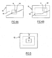
- the Figure 4A shows that the final image 10 is displayed for a first angular field value.
- the central zone 11 therefore has a first size.
- the controller 5 modifies the size of the central zone to enlarge it, which corresponds to the Figure 4B .
- the controller 5 is further adapted to reconstitute the final image 10 by using, for each zone 11 or 14 of the final image 10, the highest angular resolution available from the sensors observing a corresponding zone of the scene.
- the portion 121 of the sensor 2 most angularly solved is used, instead of the area 131 of the sensor 3 the least angularly resolved.
- the transfer of information between the portion 12 of the image of the sensor 2 and the central zone 11 of the final image 10 requires the controller 5 to convert the information into the portion 12, available with the angular resolution of the sensor 2 to the angular resolution of the image 10. Similarly, it must convert the information taken in the part 13, available with the angular resolution of the sensor 3, to the angular resolution of the image 10.
- the modification of the size and the angular resolution of the zones is advantageously carried out thanks to a digital zoom of the controller 5.
- the digital zoom function is known to those skilled in the art and is not repeated in the present description.
- the controller 5 When magnifying or reducing the images by the digital zoom, the controller 5 resamples each zone of the final image 10 according to the expected angular and / or spatial resolution of the image Release. To avoid aliasing, any image reduction is preceded by properly sized low-pass filtering.
- connection, in the final image 10, between the central zone 11 (corresponding to the portion 12 resulting from the image 120) and the peripheral zone 14 (corresponding to the peripheral portion 13 of the image 130) may, in certain applications, do not be critical. It can then be masked using a visible frame, as shown in FIG. figure 2 .
- connection can be made practically imperceptible if the controller 5 is adapted to individually re-align the different selected portions of the images 120 and 130 by correcting for errors in the actual focal length, and / or the effects of the distortion, and / or or the angular and / or parallax deviations between the lines of sight of the sensors and / or by correcting any differences in contrast and / or colorimetry between the image parts coming from the different sensors.
- This type of correction allowing a virtually imperceptible connection is known to those skilled in the art.
- the senor 2 having the highest angular resolution among the sensors is a monochrome sensor, and the other sensors are polychromatic sensors.
- the monochrome sensor has a higher spatial resolution than a full-field polychrome sensor, which increases the quality of the image at the level of the area of interest positioned in the center of the final image.
- the polychrome peripheral sensors allow them a comfort of observation to the user.
- the monochrome in the center of the final image can however be inconvenient for the user, who may wish a comfort of observation on the whole of the final image.
- the controller 5 is adapted to apply the chrominance of the central portion 132 of the image 130 - resulting from the full color sensor 3 having the highest angular resolution among the sensors covering the corresponding area of the scene to the central zone 11 of the final image 10.
- the central zone 11 is the initially monochrome portion corresponding to the central portion 12 of the image 120 from the monochrome sensor 2 having the highest angular resolution among the sensors.
- the chrominance of the portion 132 of the image 130 is then used to colorize, even coarsely, the central zone 11 of the final, initially monochrome image.
- the figure 1 shows that a third sensor 4 can also be put in place on the device.
- the number of sensors can in fact be any.
- the parts of the images coming from the sensors are positioned in decreasing order of angular resolution, from the central zone to the peripheral zone in the final image, but taking for each zone 11, 14 and 17 the the highest angular resolution available, as shown in figure 5 .
- the sensors can be sensitive in the visible range or in the infrared for example, and generally operate in the same spectral band without this being limiting, a sensor that can for example be sensitive in the visible range, and another in the infrared range. .
Landscapes
- Engineering & Computer Science (AREA)
- Multimedia (AREA)
- Signal Processing (AREA)
- Studio Devices (AREA)
- Transforming Light Signals Into Electric Signals (AREA)
- Length Measuring Devices By Optical Means (AREA)
Claims (11)
- Optische Vorrichtung (1), umfassend:- mehrere Sensoren (2, 3, 4) für Bilder (120, 130), die eine selbe Szene beobachten, indem sie eine gemeinsame Blickrichtung sowie unterschiedliche Winkelbereiche und Winkelauflösungen haben;- ein Ausgangsmedium (6) zum Auswerten eines fertigen Bildes (10), das gebildet istwobei der Controller angepasst ist, um die jeweiligen Größen der verschiedenen Zonen des fertigen Bildes in Abhängigkeit von dem Wert, der für den Winkelbereich des fertigen Bildes ausgewählt wurde, zu verändern,o in einer mittleren Zone (11) des fertigen Bildes durch ein Bild (20), das von dem Sensor (2) unter den Sensoren stammt, der die höchste Winkelauflösung hat;o in einer Randzone durch einen Randteil (13) eines Bildes (130), das von einem Sensor (3) stammt, der die niedrigste Winkelauflösung hat;dadurch gekennzeichnet, dass sie Folgendes umfasst:- ein Winkelbereichs-Auswahlmittel (8), das angepasst ist, um einem Benutzer die Auswahl eines Winkelbereichswertes für das fertige Bild zu ermöglichen,- einen Controller, der angepasst ist, um ausgehend von den Bildern, die von den verschiedenen Sensoren stammen, das fertige Bild zu bilden, das diesem Winkelbereichswert entspricht,∘ wobei die Bildteile, die von den verschiedenen Sensoren stammen und zur Bildung der verschiedenen Zonen des fertigen Bildes verwendet werden, Sensoren mit einer Winkelauflösung entsprechen, die von der mittleren Zone zu dem Rand des fertigen Bildes hin abnimmt,∘ wobei der Controller für jede Zone des fertigen Bildes einen Bildteil verwendet, der von dem Sensor unter den Sensoren, welche die Szenenzone, die der Bildzone entspricht, beobachten, mit der höchsten Winkelauflösung stammt,
und dass der Sensor (2) unter den Sensoren, der die höchste Winkelauflösung hat, ein Monochromsensor ist, wobei die anderen Sensoren (3) Polychromsensoren sind, wobei der Controller (5) angepasst ist, um die Farbigkeit des mittleren Teils (132) eines Bildes (130), der von einem Polychromsensor (2) stammt, an die mittlere Zone (11) des fertigen Bildes (10) anzuwenden. - Vorrichtung nach Anspruch 1, wobei der Controller (5) ein digitales Zoom aufweist, um die Größen zu verändern.
- Vorrichtung nach einem der Ansprüche 1 oder 2, wobei das Medium (6) am Ausgang des Controllers (5) angeordnet ist und eine Vorrichtung zum Anzeigen, Komprimieren, Speichern oder Senden ist.
- Vorrichtung nach einem der Ansprüche 1 bis 3, wobei die Sensoren die selbe Raumauflösung haben.
- Vorrichtung nach einem der Ansprüche 1 bis 3, wobei jeder Sensor eine Raumauflösung hat, die von den anderen Sensoren verschieden ist.
- Vorrichtung nach einem der Ansprüche 1 bis 5, wobei der Controller (5) die Teile (12, 13) der Bilder (120, 130) resampelt, um sie in Abhängigkeit von dem ausgewählten Wert an die Winkelauflösung des fertigen Bildes (10) anzupassen.
- Vorrichtung nach einem der Ansprüche 1 bis 6, wobei der Controller (5) angepasst ist, um die Teile der Bilder einzeln nachzustellen, indem er die Fehler in der tatsächlichen Brennweite und/oder die Verzerrungseffekte und/oder die Winkelabstände und/oder die Parallaxabstände zwischen den Ziellinien der Sensoren und/oder die eventuellen Kontrastdifferenzen und/oder Kolorimetriedifferenzen korrigiert.
- Vorrichtung nach einem der Ansprüche 1 bis 7, die mindestens drei Sensoren umfasst.
- Verfahren zum Beobachten einer Szene (7) mit Hilfe einer optischen Vorrichtung (1), die Folgendes umfasst:- mehrere Sensoren (2, 3, 4) für Bilder (120, 130), die eine selbe Szene beobachten, indem sie eine gemeinsame Blickrichtung sowie unterschiedliche Winkelbereiche und Winkelauflösungen haben;- ein Ausgangsmedium (6) zum Auswerten eines fertigen Bildes (10), das gebildet ist∘ in einer mittleren Zone (11) des fertigen Bildes durch ein Bild (20), das von dem Sensor (2) unter den Sensoren stammt, der die höchste Winkelauflösung hat;∘ in einer Randzone durch einen Randteil (13) eines Bildes (130), das von einem Sensor (3) stammt, der die niedrigste Winkelauflösung hat;- einen Controller (5), und- ein Winkelbereichs-Auswahlmittel (8),wobei das Verfahren die folgenden Schritte umfasst:- Beobachten einer Szene (7) durch die Sensoren (2, 3, 4);- Erstellen eines fertigen Bildes (10), das für das Medium (6) bestimmt ist, wobei das fertige Bild von Zonen (11, 14) gebildet ist, die Teile (12, 13) der Bilder (120, 130) enthalten, die von den Sensoren stammen;wobei das Verfahren dadurch gekennzeichnet ist, dass, da ein Winkelbereichs-Auswahlmittel (8) angepasst ist, um einem Benutzer die Auswahl eines Winkelbereichswertes für das fertige Bild zu ermöglichen, der Controller (5)- ausgehend von den Bildern, die von den verschiedenen Sensoren stammen, das fertige Bild bildet, das diesem Winkelbereichswert entspricht,∘ wobei die Bildteile, die von den verschiedenen Sensoren stammen und zur Bildung der verschiedenen Zonen des fertigen Bildes verwendet werden, Sensoren mit einer Winkelauflösung entsprechen, die von der mittleren Zone zu dem Rand des fertigen Bildes hin abnimmt,∘ wobei der Controller für jede Zone des fertigen Bildes einen Bildteil verwendet, der von dem Sensor unter den Sensoren, welche die Szenenzone, die der Bildzone entspricht, beobachten, stammt, der die höchste Winkelauflösung hat,- die jeweiligen Größen der verschiedenen Zonen des fertigen Bildes in Abhängigkeit von dem Wert, der für den Winkelbereich des fertigen Bildes aus gewählt wurde, verändert,und dass, da der Sensor (2) unter den Sensoren, der die höchste Winkelauflösung hat, ein Monochromsensor ist, wobei die anderen Sensoren (3) Polychromsensoren sind, der Controller (5) die Farbigkeit des mittleren Teils (132) eines Bildes (130), der von einem Polychromsensor (2) stammt, auf die mittlere Zone (11) des fertigen Bildes (10) anwendet.
- Verfahren nach Anspruch 9, das einen Schritt des Resampling, durch den Controller (5), der Teile (12, 13) der Bilder (120, 130) in Abhängigkeit von dem für das fertige Bild (10) ausgewählten Wert umfasst.
- Verfahren nach einem der Ansprüche 9 oder 10, das einen Schritt der einzelnen Nachstellung der Teile der Bilder, durch den Controller (5), umfasst, indem er die Fehler in der tatsächlichen Brennweite und/oder die Verzerrungseffekte und/oder die Winkelabstände und/oder die Parallaxabstände zwischen den Ziellinien der Sensoren und/oder die eventuellen Kontrastdifferenzen und/oder Kolorimetriedifferenzen korrigiert.
Applications Claiming Priority (1)
| Application Number | Priority Date | Filing Date | Title |
|---|---|---|---|
| FR0754364A FR2914811B1 (fr) | 2007-04-06 | 2007-04-06 | Dispositif optique comportant au moins deux capteurs, procede de mise en oeuvre correspondant |
Publications (2)
| Publication Number | Publication Date |
|---|---|
| EP1978740A1 EP1978740A1 (de) | 2008-10-08 |
| EP1978740B1 true EP1978740B1 (de) | 2015-05-06 |
Family
ID=38739884
Family Applications (1)
| Application Number | Title | Priority Date | Filing Date |
|---|---|---|---|
| EP20080103146 Active EP1978740B1 (de) | 2007-04-06 | 2008-03-28 | Optische Vorrichtung mit mindestens zwei Sensoren und entsprechendes Ausführungsverfahren |
Country Status (5)
| Country | Link |
|---|---|
| EP (1) | EP1978740B1 (de) |
| CA (1) | CA2628576A1 (de) |
| FR (1) | FR2914811B1 (de) |
| IL (1) | IL190633A (de) |
| ZA (1) | ZA200803000B (de) |
Families Citing this family (3)
| Publication number | Priority date | Publication date | Assignee | Title |
|---|---|---|---|---|
| WO2015010098A1 (en) * | 2013-07-19 | 2015-01-22 | Google Inc. | Asymmetric sensor array for capturing images |
| US10591969B2 (en) | 2013-10-25 | 2020-03-17 | Google Technology Holdings LLC | Sensor-based near-field communication authentication |
| FR3088790B1 (fr) * | 2018-11-20 | 2020-11-27 | Safran Electronics & Defense | Appareil et procédé pour observer une scène comportant une cible |
Citations (2)
| Publication number | Priority date | Publication date | Assignee | Title |
|---|---|---|---|---|
| EP0473310A2 (de) * | 1990-08-31 | 1992-03-04 | Hughes Aircraft Company | Erzeugung einer Datenbank für Schrägbilder |
| US20060056056A1 (en) * | 2004-07-19 | 2006-03-16 | Grandeye Ltd. | Automatically expanding the zoom capability of a wide-angle video camera |
Family Cites Families (2)
| Publication number | Priority date | Publication date | Assignee | Title |
|---|---|---|---|---|
| JP2000041176A (ja) * | 1998-07-24 | 2000-02-08 | Canon Inc | 制御装置、制御システム、制御方法、及び記憶媒体 |
| WO2005125209A1 (en) * | 2004-06-22 | 2005-12-29 | Stratech Systems Limited | Method and system for surveillance of vessels |
-
2007
- 2007-04-06 FR FR0754364A patent/FR2914811B1/fr not_active Expired - Fee Related
-
2008
- 2008-03-28 EP EP20080103146 patent/EP1978740B1/de active Active
- 2008-04-03 CA CA002628576A patent/CA2628576A1/fr not_active Abandoned
- 2008-04-04 ZA ZA200803000A patent/ZA200803000B/xx unknown
- 2008-04-06 IL IL190633A patent/IL190633A/en active IP Right Grant
Patent Citations (2)
| Publication number | Priority date | Publication date | Assignee | Title |
|---|---|---|---|---|
| EP0473310A2 (de) * | 1990-08-31 | 1992-03-04 | Hughes Aircraft Company | Erzeugung einer Datenbank für Schrägbilder |
| US20060056056A1 (en) * | 2004-07-19 | 2006-03-16 | Grandeye Ltd. | Automatically expanding the zoom capability of a wide-angle video camera |
Non-Patent Citations (1)
| Title |
|---|
| RICHARD C. SIMMONS ET AL: "<title>The design of passively athermalized narrow- and wide-field-of-view infrared objectives for the OBSERVER unmanned air vehicle</title>", PROCEEDINGS OF SPIE, vol. 5612, 6 December 2004 (2004-12-06), pages 236 - 248, XP055147887, ISSN: 0277-786X, DOI: 10.1117/12.582510 * |
Also Published As
| Publication number | Publication date |
|---|---|
| FR2914811B1 (fr) | 2010-04-30 |
| CA2628576A1 (fr) | 2008-10-06 |
| IL190633A0 (en) | 2008-12-29 |
| IL190633A (en) | 2015-04-30 |
| FR2914811A1 (fr) | 2008-10-10 |
| ZA200803000B (en) | 2008-12-31 |
| EP1978740A1 (de) | 2008-10-08 |
Similar Documents
| Publication | Publication Date | Title |
|---|---|---|
| US9319585B1 (en) | High resolution array camera | |
| CN105009168B (zh) | 复原滤波器生成装置以及方法、图像处理装置以及方法、摄像装置 | |
| CA2909554A1 (fr) | Dispositif d'acquisition d'images bimode | |
| WO2008068257A1 (fr) | Dispositif d'affichage d'images par projection a deux etages de modulation | |
| EP1978740B1 (de) | Optische Vorrichtung mit mindestens zwei Sensoren und entsprechendes Ausführungsverfahren | |
| FR3115894A1 (fr) | Appareil de projection d’images et unité de pilotage associée | |
| EP3084507A1 (de) | Optisches bildgebungsmodul mit hyper-hemisphärischem feld und kontrollierter verzerrung sowie kompatibilität mit einer externen umgebung | |
| EP2572227B1 (de) | Optisches system zur dynamischen korrektur eines bildes | |
| US8508613B2 (en) | Image capturing apparatus | |
| FR3065537B1 (fr) | Systeme optronique pour plate-forme et plate-forme associee | |
| WO2021156581A1 (fr) | Appareil pour l'observation d'un astre | |
| EP3024011B1 (de) | System zur bilderfassung bei geringer lichtstärke, das ein optiksystem mit einem phasen- und/oder amplitudenfilter umfasst | |
| FR3026851A1 (fr) | Procede de realisation d'une optique de couplage pour systeme de captation d'images a bas niveau de lumiere et optique de couplage associee | |
| EP1141648A1 (de) | Methode und hilfsvorrichtung zum zielen mit handfeuerwaffen | |
| Samuels et al. | Performance of new low-cost 1/3" security cameras for meteor surveillance | |
| WO2026021754A1 (fr) | Procédé de construction d'une image, dispositif électronique et programme d'ordinateur associés | |
| EP3818391B1 (de) | Optronische sicht und zugehörige plattform | |
| WO2026021756A1 (fr) | Procédé de construction d'une image, dispositif électronique et programme d'ordinateur associés | |
| US20250016295A1 (en) | Camera module with chromatic aberration correction | |
| CA3240417A1 (fr) | Viseur pour systeme de tir | |
| WO2025017261A1 (fr) | Procédé pour la calibration de l'affichage d'images dans un casque de réalité mixte | |
| WO2026003443A1 (fr) | Procede pour imager et representer une scene, dispositif d'imagerie et appareil electronique associes | |
| FR2973892A1 (fr) | Systeme de conduite infrarouge stereoscopique a profondeur de champ augmentee | |
| WO2015075085A1 (fr) | Procédé d'estimation du mouvement d'un objet | |
| CA3064077A1 (fr) | Procede pour verifier l'affichage d'un contenu par un dispositif d'affichage numerique et systeme d'affichage numerique |
Legal Events
| Date | Code | Title | Description |
|---|---|---|---|
| PUAI | Public reference made under article 153(3) epc to a published international application that has entered the european phase |
Free format text: ORIGINAL CODE: 0009012 |
|
| 17P | Request for examination filed |
Effective date: 20080328 |
|
| AK | Designated contracting states |
Kind code of ref document: A1 Designated state(s): AT BE BG CH CY CZ DE DK EE ES FI FR GB GR HR HU IE IS IT LI LT LU LV MC MT NL NO PL PT RO SE SI SK TR |
|
| AX | Request for extension of the european patent |
Extension state: AL BA MK RS |
|
| 17Q | First examination report despatched |
Effective date: 20090429 |
|
| AKX | Designation fees paid |
Designated state(s): AT BE BG CH CY CZ DE DK EE ES FI FR GB GR HR HU IE IS IT LI LT LU LV MC MT NL NO PL PT RO SE SI SK TR |
|
| RAP1 | Party data changed (applicant data changed or rights of an application transferred) |
Owner name: SAGEM DEFENSE SECURITE |
|
| GRAP | Despatch of communication of intention to grant a patent |
Free format text: ORIGINAL CODE: EPIDOSNIGR1 |
|
| INTG | Intention to grant announced |
Effective date: 20141211 |
|
| GRAS | Grant fee paid |
Free format text: ORIGINAL CODE: EPIDOSNIGR3 |
|
| GRAA | (expected) grant |
Free format text: ORIGINAL CODE: 0009210 |
|
| AK | Designated contracting states |
Kind code of ref document: B1 Designated state(s): AT BE BG CH CY CZ DE DK EE ES FI FR GB GR HR HU IE IS IT LI LT LU LV MC MT NL NO PL PT RO SE SI SK TR |
|
| REG | Reference to a national code |
Ref country code: GB Ref legal event code: FG4D Free format text: NOT ENGLISH |
|
| REG | Reference to a national code |
Ref country code: CH Ref legal event code: EP |
|
| REG | Reference to a national code |
Ref country code: IE Ref legal event code: FG4D Free format text: LANGUAGE OF EP DOCUMENT: FRENCH |
|
| REG | Reference to a national code |
Ref country code: AT Ref legal event code: REF Ref document number: 726391 Country of ref document: AT Kind code of ref document: T Effective date: 20150615 |
|
| REG | Reference to a national code |
Ref country code: DE Ref legal event code: R096 Ref document number: 602008038012 Country of ref document: DE Effective date: 20150618 |
|
| REG | Reference to a national code |
Ref country code: SE Ref legal event code: TRGR |
|
| REG | Reference to a national code |
Ref country code: AT Ref legal event code: MK05 Ref document number: 726391 Country of ref document: AT Kind code of ref document: T Effective date: 20150506 |
|
| REG | Reference to a national code |
Ref country code: NL Ref legal event code: MP Effective date: 20150506 |
|
| REG | Reference to a national code |
Ref country code: LT Ref legal event code: MG4D |
|
| PG25 | Lapsed in a contracting state [announced via postgrant information from national office to epo] |
Ref country code: LT Free format text: LAPSE BECAUSE OF FAILURE TO SUBMIT A TRANSLATION OF THE DESCRIPTION OR TO PAY THE FEE WITHIN THE PRESCRIBED TIME-LIMIT Effective date: 20150506 Ref country code: FI Free format text: LAPSE BECAUSE OF FAILURE TO SUBMIT A TRANSLATION OF THE DESCRIPTION OR TO PAY THE FEE WITHIN THE PRESCRIBED TIME-LIMIT Effective date: 20150506 Ref country code: PT Free format text: LAPSE BECAUSE OF FAILURE TO SUBMIT A TRANSLATION OF THE DESCRIPTION OR TO PAY THE FEE WITHIN THE PRESCRIBED TIME-LIMIT Effective date: 20150907 Ref country code: NO Free format text: LAPSE BECAUSE OF FAILURE TO SUBMIT A TRANSLATION OF THE DESCRIPTION OR TO PAY THE FEE WITHIN THE PRESCRIBED TIME-LIMIT Effective date: 20150806 Ref country code: HR Free format text: LAPSE BECAUSE OF FAILURE TO SUBMIT A TRANSLATION OF THE DESCRIPTION OR TO PAY THE FEE WITHIN THE PRESCRIBED TIME-LIMIT Effective date: 20150506 Ref country code: ES Free format text: LAPSE BECAUSE OF FAILURE TO SUBMIT A TRANSLATION OF THE DESCRIPTION OR TO PAY THE FEE WITHIN THE PRESCRIBED TIME-LIMIT Effective date: 20150506 |
|
| PG25 | Lapsed in a contracting state [announced via postgrant information from national office to epo] |
Ref country code: GR Free format text: LAPSE BECAUSE OF FAILURE TO SUBMIT A TRANSLATION OF THE DESCRIPTION OR TO PAY THE FEE WITHIN THE PRESCRIBED TIME-LIMIT Effective date: 20150807 Ref country code: IS Free format text: LAPSE BECAUSE OF FAILURE TO SUBMIT A TRANSLATION OF THE DESCRIPTION OR TO PAY THE FEE WITHIN THE PRESCRIBED TIME-LIMIT Effective date: 20150906 Ref country code: BG Free format text: LAPSE BECAUSE OF FAILURE TO SUBMIT A TRANSLATION OF THE DESCRIPTION OR TO PAY THE FEE WITHIN THE PRESCRIBED TIME-LIMIT Effective date: 20150806 Ref country code: AT Free format text: LAPSE BECAUSE OF FAILURE TO SUBMIT A TRANSLATION OF THE DESCRIPTION OR TO PAY THE FEE WITHIN THE PRESCRIBED TIME-LIMIT Effective date: 20150506 Ref country code: LV Free format text: LAPSE BECAUSE OF FAILURE TO SUBMIT A TRANSLATION OF THE DESCRIPTION OR TO PAY THE FEE WITHIN THE PRESCRIBED TIME-LIMIT Effective date: 20150506 |
|
| PG25 | Lapsed in a contracting state [announced via postgrant information from national office to epo] |
Ref country code: EE Free format text: LAPSE BECAUSE OF FAILURE TO SUBMIT A TRANSLATION OF THE DESCRIPTION OR TO PAY THE FEE WITHIN THE PRESCRIBED TIME-LIMIT Effective date: 20150506 Ref country code: DK Free format text: LAPSE BECAUSE OF FAILURE TO SUBMIT A TRANSLATION OF THE DESCRIPTION OR TO PAY THE FEE WITHIN THE PRESCRIBED TIME-LIMIT Effective date: 20150506 |
|
| REG | Reference to a national code |
Ref country code: DE Ref legal event code: R097 Ref document number: 602008038012 Country of ref document: DE |
|
| REG | Reference to a national code |
Ref country code: FR Ref legal event code: PLFP Year of fee payment: 9 |
|
| PG25 | Lapsed in a contracting state [announced via postgrant information from national office to epo] |
Ref country code: PL Free format text: LAPSE BECAUSE OF FAILURE TO SUBMIT A TRANSLATION OF THE DESCRIPTION OR TO PAY THE FEE WITHIN THE PRESCRIBED TIME-LIMIT Effective date: 20150506 Ref country code: SK Free format text: LAPSE BECAUSE OF FAILURE TO SUBMIT A TRANSLATION OF THE DESCRIPTION OR TO PAY THE FEE WITHIN THE PRESCRIBED TIME-LIMIT Effective date: 20150506 Ref country code: CZ Free format text: LAPSE BECAUSE OF FAILURE TO SUBMIT A TRANSLATION OF THE DESCRIPTION OR TO PAY THE FEE WITHIN THE PRESCRIBED TIME-LIMIT Effective date: 20150506 Ref country code: RO Free format text: LAPSE BECAUSE OF NON-PAYMENT OF DUE FEES Effective date: 20150506 |
|
| PLBE | No opposition filed within time limit |
Free format text: ORIGINAL CODE: 0009261 |
|
| STAA | Information on the status of an ep patent application or granted ep patent |
Free format text: STATUS: NO OPPOSITION FILED WITHIN TIME LIMIT |
|
| 26N | No opposition filed |
Effective date: 20160209 |
|
| PG25 | Lapsed in a contracting state [announced via postgrant information from national office to epo] |
Ref country code: SI Free format text: LAPSE BECAUSE OF FAILURE TO SUBMIT A TRANSLATION OF THE DESCRIPTION OR TO PAY THE FEE WITHIN THE PRESCRIBED TIME-LIMIT Effective date: 20150506 |
|
| PG25 | Lapsed in a contracting state [announced via postgrant information from national office to epo] |
Ref country code: MC Free format text: LAPSE BECAUSE OF FAILURE TO SUBMIT A TRANSLATION OF THE DESCRIPTION OR TO PAY THE FEE WITHIN THE PRESCRIBED TIME-LIMIT Effective date: 20150506 Ref country code: LU Free format text: LAPSE BECAUSE OF FAILURE TO SUBMIT A TRANSLATION OF THE DESCRIPTION OR TO PAY THE FEE WITHIN THE PRESCRIBED TIME-LIMIT Effective date: 20160328 |
|
| REG | Reference to a national code |
Ref country code: CH Ref legal event code: PL |
|
| REG | Reference to a national code |
Ref country code: IE Ref legal event code: MM4A |
|
| PG25 | Lapsed in a contracting state [announced via postgrant information from national office to epo] |
Ref country code: IE Free format text: LAPSE BECAUSE OF NON-PAYMENT OF DUE FEES Effective date: 20160328 Ref country code: LI Free format text: LAPSE BECAUSE OF NON-PAYMENT OF DUE FEES Effective date: 20160331 Ref country code: CH Free format text: LAPSE BECAUSE OF NON-PAYMENT OF DUE FEES Effective date: 20160331 |
|
| REG | Reference to a national code |
Ref country code: FR Ref legal event code: PLFP Year of fee payment: 10 |
|
| PG25 | Lapsed in a contracting state [announced via postgrant information from national office to epo] |
Ref country code: IT Free format text: LAPSE BECAUSE OF NON-PAYMENT OF DUE FEES Effective date: 20160328 Ref country code: NL Free format text: LAPSE BECAUSE OF FAILURE TO SUBMIT A TRANSLATION OF THE DESCRIPTION OR TO PAY THE FEE WITHIN THE PRESCRIBED TIME-LIMIT Effective date: 20150506 |
|
| PG25 | Lapsed in a contracting state [announced via postgrant information from national office to epo] |
Ref country code: MT Free format text: LAPSE BECAUSE OF FAILURE TO SUBMIT A TRANSLATION OF THE DESCRIPTION OR TO PAY THE FEE WITHIN THE PRESCRIBED TIME-LIMIT Effective date: 20150506 |
|
| REG | Reference to a national code |
Ref country code: FR Ref legal event code: PLFP Year of fee payment: 11 |
|
| PG25 | Lapsed in a contracting state [announced via postgrant information from national office to epo] |
Ref country code: HU Free format text: LAPSE BECAUSE OF FAILURE TO SUBMIT A TRANSLATION OF THE DESCRIPTION OR TO PAY THE FEE WITHIN THE PRESCRIBED TIME-LIMIT; INVALID AB INITIO Effective date: 20080328 Ref country code: CY Free format text: LAPSE BECAUSE OF FAILURE TO SUBMIT A TRANSLATION OF THE DESCRIPTION OR TO PAY THE FEE WITHIN THE PRESCRIBED TIME-LIMIT Effective date: 20150506 |
|
| PG25 | Lapsed in a contracting state [announced via postgrant information from national office to epo] |
Ref country code: TR Free format text: LAPSE BECAUSE OF FAILURE TO SUBMIT A TRANSLATION OF THE DESCRIPTION OR TO PAY THE FEE WITHIN THE PRESCRIBED TIME-LIMIT Effective date: 20150506 |
|
| PGFP | Annual fee paid to national office [announced via postgrant information from national office to epo] |
Ref country code: DE Payment date: 20250218 Year of fee payment: 18 |
|
| PGFP | Annual fee paid to national office [announced via postgrant information from national office to epo] |
Ref country code: SE Payment date: 20250218 Year of fee payment: 18 |
|
| PGFP | Annual fee paid to national office [announced via postgrant information from national office to epo] |
Ref country code: BE Payment date: 20250218 Year of fee payment: 18 |
|
| PGFP | Annual fee paid to national office [announced via postgrant information from national office to epo] |
Ref country code: FR Payment date: 20250218 Year of fee payment: 18 |
|
| PGFP | Annual fee paid to national office [announced via postgrant information from national office to epo] |
Ref country code: GB Payment date: 20250221 Year of fee payment: 18 |