EP1978781A1 - Récepteur d'appareil auditif doté de compensation de vibrations - Google Patents
Récepteur d'appareil auditif doté de compensation de vibrations Download PDFInfo
- Publication number
- EP1978781A1 EP1978781A1 EP08251276A EP08251276A EP1978781A1 EP 1978781 A1 EP1978781 A1 EP 1978781A1 EP 08251276 A EP08251276 A EP 08251276A EP 08251276 A EP08251276 A EP 08251276A EP 1978781 A1 EP1978781 A1 EP 1978781A1
- Authority
- EP
- European Patent Office
- Prior art keywords
- armature
- hearing aid
- active
- housing
- aid receiver
- Prior art date
- Legal status (The legal status is an assumption and is not a legal conclusion. Google has not performed a legal analysis and makes no representation as to the accuracy of the status listed.)
- Withdrawn
Links
Images
Classifications
-
- H—ELECTRICITY
- H04—ELECTRIC COMMUNICATION TECHNIQUE
- H04R—LOUDSPEAKERS, MICROPHONES, GRAMOPHONE PICK-UPS OR LIKE ACOUSTIC ELECTROMECHANICAL TRANSDUCERS; ELECTRIC HEARING AIDS; PUBLIC ADDRESS SYSTEMS
- H04R11/00—Transducers of moving-armature or moving-core type
- H04R11/02—Loudspeakers
-
- H—ELECTRICITY
- H04—ELECTRIC COMMUNICATION TECHNIQUE
- H04R—LOUDSPEAKERS, MICROPHONES, GRAMOPHONE PICK-UPS OR LIKE ACOUSTIC ELECTROMECHANICAL TRANSDUCERS; ELECTRIC HEARING AIDS; PUBLIC ADDRESS SYSTEMS
- H04R2209/00—Details of transducers of the moving-coil, moving-strip, or moving-wire type covered by H04R9/00 but not provided for in any of its subgroups
- H04R2209/027—Electrical or mechanical reduction of yoke vibration
-
- H—ELECTRICITY
- H04—ELECTRIC COMMUNICATION TECHNIQUE
- H04R—LOUDSPEAKERS, MICROPHONES, GRAMOPHONE PICK-UPS OR LIKE ACOUSTIC ELECTROMECHANICAL TRANSDUCERS; ELECTRIC HEARING AIDS; PUBLIC ADDRESS SYSTEMS
- H04R25/00—Electric hearing aids
-
- H—ELECTRICITY
- H04—ELECTRIC COMMUNICATION TECHNIQUE
- H04R—LOUDSPEAKERS, MICROPHONES, GRAMOPHONE PICK-UPS OR LIKE ACOUSTIC ELECTROMECHANICAL TRANSDUCERS; ELECTRIC HEARING AIDS; PUBLIC ADDRESS SYSTEMS
- H04R25/00—Electric hearing aids
- H04R25/45—Prevention of acoustic reaction, i.e. acoustic oscillatory feedback
- H04R25/456—Prevention of acoustic reaction, i.e. acoustic oscillatory feedback mechanically
Definitions
- the present invention is directed to a hearing aid receiver that has a vibration compensation component, helping to reduce feedback and other problems associated with vibration.
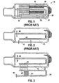
- FIG. 1 A typical construction of a hearing aid receiver 10 is shown on Fig. 1 . Its construction is described in, e.g., U.S. Patent No. 6,078,677 , herein incorporated by reference.
- the basic components of this receiver 10 include a U-shaped armature 20 that is driven by an electric coil 36 coupled with a magnetic member 38 that together comprise a motor.
- the motor is an electromechanical part of a transducer that takes an electrical input and produces a mechanical force/member velocity.
- a diaphragm layer 32 is provided with a reinforcement layer 30. The diaphragm, which is attached to the motor, converts the mechanical vibrations into sound pressure.
- These components are contained within a housing or case 42.
- FIG. 2 A simplified vibration model is shown in Figure 2 in which the particularly relevant components are highlighted.
- a completely-in-canal (CIC) hearing aid e.g.
- This model comprises a case 42 and a U-shaped armature 20 that is attached to the case 42 via an armature support 40, which may be implemented as, e.g., a rigid block (which may be implemented as a part of the motor).
- the motor 36, 38 of the receiver 10 creates forces that cause the U-shape armature 20 to vibrate: 1) a force applied to the U-shaped armature 50, and 2) a reaction force applied to the case 42 via the block 40.
- the vibrating elements of the motor 36, 38 cause the receiver 10 itself to vibrate.
- the receiver 10 has to be isolated from direct mechanical contact with the shell or other components inside the hearing instrument.
- the receiver 10 of a typical CIC instrument is placed inside the CIC shell and attached to the shell tip with a flexible tube (not shown).
- the tube feeds the sound pressure, generated by the receiver 10, into the ear of the user.
- the tube also isolates the vibrations that the receiver 10 creates from spreading into the CIC instrument.
- a receiver 10 creates maximum amount of vibrations near the resonance frequency of the U-shaped armature 20 (typical value around 2-3 kHz), so that a typical hearing device may develop feedback near such a resonance frequency.
- a construction of a receiver according to various embodiments of the invention includes a vibrational compensation component having vibrational characteristics similar to the active/driven U-shaped armature.
- a hearing aid receiver comprising: a housing having an inside surface and an outside surface; a motor; an active armature that is attached to the motor and attached to the inside surface of the housing, the active armature being driven in a vibrational manner by the motor; and an external passive component that is attached to the outside surface of the housing, the external passive component designed to vibrate in a direction opposed to vibrations of the active armature.
- the external passive component may mirror the shape of the active armature, and the external passive component may be attached to the outside surface of the housing in a direction of a mirror reflection of the active armature.
- a corresponding method for operating a hearing aid receiver comprising: actively vibrating an active armature that is attached to a motor within a housing, the housing having an inside surface and an outside surface; and passively vibrating a passive component that is attached to the outside surface of the housing in a direction opposite to vibrations of the active armature.
- FIG 3 illustrates an embodiment of the inventive receiver 10 construction.
- the receiver 10 comprises the elements illustrated in Figure 2 , but further includes, in addition to the active or driven U-shaped armature 20, a passive U-shaped armature 20'.
- the passive U-shaped armature 20' is attached to the receiver case 42 via a passive armature support 40', which may also be implemented as a rigid block 40' in such a way that its position is a mirror-reflection of the position of the active U-shaped armature 20.
- the resonance frequency of the passive U-shaped armature 20' should be equal or close to the resonance frequency of the active U-shaped armature 20.
- the passive armature 20' mimics the shape of the active armature 20. This makes it more likely that the passive armature's 20' vibration pattern will mimic that of the active armature 20.
- the design is not so limited, and it is also possible to design a passive armature 20' to be of a different shape, particularly if only narrow bands of frequencies are of concern.
- the passive U-shaped armature 20' becomes excited by vibrations of the receiver.
- the directions of vibrations 50' of the passive U-shaped armature 20' become opposite to the directions of vibrations 50 of the active U-shaped armature 20 at the resonance frequency of the U-shaped armatures 20, 20'. Therefore the passive U-shaped armature 20' acts to compensate the receiver vibrations 50 in the region of the U-shape armature resonance and thereby reducing the feedback tendency of a hearing aid.
- a damper 21' may be provided that allows adjusting the amount of a vibrational compensation and width of the frequency region/band where the compensation takes place.
- the damper can prevent a situation in which the passive armature 20' begins to vibrate with a very high amplitude, thereby "over-compensating" for the vibration of the active armature 20 by generating excessive opposing vibrations.
- the damper has high internal friction losses.
- Such a construction can be realized with a block of viscous material, a drop of a semi-liquid damping fluid, viscous oil, etc.
- the present invention may be described in terms of functional block components and various processing steps. Such functional blocks may be realized by any number of hardware components configured to perform the specified functions. Furthermore, the present invention could employ any number of conventional techniques for electronics configuration, signal processing and/or control, data processing and the like.
Landscapes
- Physics & Mathematics (AREA)
- Electromagnetism (AREA)
- Engineering & Computer Science (AREA)
- Acoustics & Sound (AREA)
- Signal Processing (AREA)
- Apparatuses For Generation Of Mechanical Vibrations (AREA)
Applications Claiming Priority (1)
| Application Number | Priority Date | Filing Date | Title |
|---|---|---|---|
| US11/696,435 US8160283B2 (en) | 2007-04-04 | 2007-04-04 | Hearing aid receiver with vibration compensation |
Publications (1)
| Publication Number | Publication Date |
|---|---|
| EP1978781A1 true EP1978781A1 (fr) | 2008-10-08 |
Family
ID=39496113
Family Applications (1)
| Application Number | Title | Priority Date | Filing Date |
|---|---|---|---|
| EP08251276A Withdrawn EP1978781A1 (fr) | 2007-04-04 | 2008-04-01 | Récepteur d'appareil auditif doté de compensation de vibrations |
Country Status (2)
| Country | Link |
|---|---|
| US (1) | US8160283B2 (fr) |
| EP (1) | EP1978781A1 (fr) |
Families Citing this family (4)
| Publication number | Priority date | Publication date | Assignee | Title |
|---|---|---|---|---|
| DE102010022323A1 (de) | 2010-06-01 | 2011-12-01 | Siemens Medical Instruments Pte. Ltd. | Tief-Ohrkanal-Hörinstrument |
| EP2503792B1 (fr) * | 2011-03-21 | 2018-05-16 | Sonion Nederland B.V. | Haut-parleur à armature mobile avec suppression des vibrations |
| US9473855B2 (en) * | 2011-03-21 | 2016-10-18 | Sonion Nederland B.V. | Moving armature receiver assemblies with vibration suppression |
| EP3051841B1 (fr) * | 2015-01-30 | 2020-10-07 | Sonion Nederland B.V. | Récepteur ayant un ensemble de moteur suspendu |
Citations (4)
| Publication number | Priority date | Publication date | Assignee | Title |
|---|---|---|---|---|
| US3257516A (en) * | 1962-06-25 | 1966-06-21 | Knowles Electronies Inc | Combined instrument and transducer motor cavities for acoustic instrument |
| US4109116A (en) * | 1977-07-19 | 1978-08-22 | Victoreen John A | Hearing aid receiver with plural transducers |
| US6078677A (en) | 1996-12-23 | 2000-06-20 | Microtronic Nederlands B.V. | Electroacoustic transducer with improved diaphragm attachment |
| US20020146141A1 (en) | 2001-04-04 | 2002-10-10 | Onno Geschiere | Acoustic receiver having improved mechanical suspension |
-
2007
- 2007-04-04 US US11/696,435 patent/US8160283B2/en not_active Expired - Fee Related
-
2008
- 2008-04-01 EP EP08251276A patent/EP1978781A1/fr not_active Withdrawn
Patent Citations (4)
| Publication number | Priority date | Publication date | Assignee | Title |
|---|---|---|---|---|
| US3257516A (en) * | 1962-06-25 | 1966-06-21 | Knowles Electronies Inc | Combined instrument and transducer motor cavities for acoustic instrument |
| US4109116A (en) * | 1977-07-19 | 1978-08-22 | Victoreen John A | Hearing aid receiver with plural transducers |
| US6078677A (en) | 1996-12-23 | 2000-06-20 | Microtronic Nederlands B.V. | Electroacoustic transducer with improved diaphragm attachment |
| US20020146141A1 (en) | 2001-04-04 | 2002-10-10 | Onno Geschiere | Acoustic receiver having improved mechanical suspension |
Also Published As
| Publication number | Publication date |
|---|---|
| US20080247578A1 (en) | 2008-10-09 |
| US8160283B2 (en) | 2012-04-17 |
Similar Documents
| Publication | Publication Date | Title |
|---|---|---|
| JP7469688B2 (ja) | 振動アクチュエータ及び電子機器 | |
| JP6753571B2 (ja) | 振動アクチュエータ及び電子機器 | |
| US7206428B2 (en) | Acoustic receiver having improved mechanical suspension | |
| JP7658530B2 (ja) | 振動アクチュエータ及び電子機器 | |
| JP4784398B2 (ja) | 音響加振器およびこれを用いたスピーカ | |
| EP2338219B1 (fr) | Moteur vibrant | |
| US20050276434A1 (en) | Dynamic exciter and loudspeaker using the same | |
| KR20200138043A (ko) | 진동 액추에이터 및 전자기기 | |
| KR101514677B1 (ko) | 골전도 출력장치 | |
| EP4112192A1 (fr) | Actionneur de vibration et dispositif électronique | |
| EP2031898A1 (fr) | Instrument auditif logé entièrement dans le canal auditif doté d'une bonne stabilité de retour robuste | |
| KR101907519B1 (ko) | 음향출력과 진동기능을 제공하는 스피콤 | |
| EP1978781A1 (fr) | Récepteur d'appareil auditif doté de compensation de vibrations | |
| CN106507252A (zh) | 多谐振系统骨传导扬声器单体 | |
| KR100786928B1 (ko) | 다기능형 진동 액추에이터 및 휴대 단말기기 | |
| WO2018051802A1 (fr) | Dispositif de génération de vibrations sonores et instrument électronique | |
| US20250332612A1 (en) | Vibration actuator and electronic apparatus | |
| EP1978783A2 (fr) | Construction d'appareils auditifs logés entièrement dans le canal auditif dotés d'un compartiment récepteur | |
| JP5680487B2 (ja) | 音響装置およびその振動伝達方法 | |
| JP7789551B2 (ja) | 知覚可能な出力を呈示するアクチュエータ及びシステム | |
| KR20190105263A (ko) | 와이드 밴드 선형 진동 모터 | |
| KR20190103805A (ko) | 와이드 밴드 선형 진동 모터 | |
| JPH11275833A (ja) | 振動アクチュエータ |
Legal Events
| Date | Code | Title | Description |
|---|---|---|---|
| PUAI | Public reference made under article 153(3) epc to a published international application that has entered the european phase |
Free format text: ORIGINAL CODE: 0009012 |
|
| AK | Designated contracting states |
Kind code of ref document: A1 Designated state(s): AT BE BG CH CY CZ DE DK EE ES FI FR GB GR HR HU IE IS IT LI LT LU LV MC MT NL NO PL PT RO SE SI SK TR |
|
| AX | Request for extension of the european patent |
Extension state: AL BA MK RS |
|
| 17P | Request for examination filed |
Effective date: 20090406 |
|
| 17Q | First examination report despatched |
Effective date: 20090515 |
|
| AKX | Designation fees paid |
Designated state(s): AT BE BG CH CY CZ DE DK EE ES FI FR GB GR HR HU IE IS IT LI LT LU LV MC MT NL NO PL PT RO SE SI SK TR |
|
| STAA | Information on the status of an ep patent application or granted ep patent |
Free format text: STATUS: THE APPLICATION IS DEEMED TO BE WITHDRAWN |
|
| 18D | Application deemed to be withdrawn |
Effective date: 20130806 |